Patent application title: Inertial sensor tracking system
Inventors:
Russell M. Breeding (Medina, OH, US)
IPC8 Class: AG08B2100FI
USPC Class:
340670
Class name: Condition responsive indicating system specific condition velocity
Publication date: 2009-01-01
Patent application number: 20090002186
Inventors list |
Agents list |
Assignees list |
List by place |
Classification tree browser |
Top 100 Inventors |
Top 100 Agents |
Top 100 Assignees |
Usenet FAQ Index |
Documents |
Other FAQs |
Patent application title: Inertial sensor tracking system
Inventors:
Russell M. Breeding
Agents:
SAND & SEBOLT
Assignees:
Origin: CANTON, OH US
IPC8 Class: AG08B2100FI
USPC Class:
340670
Abstract:
A tracking system allows for the tracking of underground mine equipment
and personnel and is particularly useful in locating miners under
emergency circumstances in order to expedite their rescue. The system
includes an inertial sensor which is suitably sized to be carried by an
individual or mounted on mine equipment. Velocity data signals are
transmitted from the inertial sensor so that equipment and miners may be
tracked at a remote location with the use of a computer. Typically, a
transmitter sends wireless signals from the inertial sensor to the
computer via several underground transceivers. An underground charging
and reset station is provided for charging a battery used with the
inertial sensor and for setting alignment of the inertial sensor to a
home position. A pair of underground geodetic survey monuments typically
facilitate alignment of the inertial sensor to the home position.Claims:
1. A tracking system comprising:an inertial sensor for producing velocity
data in response to its movement; anda pair of underground geodetic
survey monuments to facilitate alignment of the inertial sensor to a home
position.
2. The system of claim 1 further comprising a battery mounted on the inertial sensor; and an underground charging and reset station at which the inertial sensor is positionable for charging the battery and resetting alignment of the inertial sensor to a home position.
3. The system of claim 2 wherein the battery is operatively connected to the inertial sensor for powering the inertial sensor.
4. The system of claim 2 further comprising a wireless transmitter in communication with the inertial sensor for transmitting the velocity data via a wireless signal; and wherein the battery is operatively connected to the transmitter for powering the transmitter.
5. The system of claim 1 further comprising software for translating the velocity data into location data indicative of a location of the inertial sensor.
6. The system of claim 5 further comprising a computer for running the software.
7. The system of claim 1 further comprising a computer in communication with the inertial sensor and programmed to translate the velocity data into location data indicative of a location of the inertial sensor.
8. The system of claim 1 further comprising a wireless transmitter in communication with the inertial sensor for transmitting the velocity data via a wireless signal.
9. The system of claim 8 further comprising a plurality of transceivers for relaying the velocity data signal from the transmitter.
10. The system of claim 9 further comprising a computer in wireless communication with the transceivers and programmed to translate the velocity data into location data indicative of a location of the inertial sensor.
11. The system of claim 1 further comprising an underground reset station at which the inertial sensor is positionable for setting alignment of the inertial sensor to a home position.
12. The system of claim 11 wherein the survey monuments and reset station are orthogonally oriented.
13. The system of claim 1 further comprising an underground mirror; wherein the survey monuments and mirror are orthogonally oriented.
14. A tracking system comprising:an inertial sensor for producing velocity data in response to its movement;a battery mounted on the inertial sensor; andan underground charging and reset station at which the inertial sensor is positionable for charging the battery and resetting alignment of the inertial sensor to a home position.
15. The system of claim 14 further comprising software for translating the velocity data into location data indicative of a location of the inertial sensor.
16. The system of claim 15 further comprising a computer for running the software.
17. The system of claim 14 further comprising a wireless transmitter in communication with the inertial sensor for transmitting the velocity data via a wireless signal.
18. The system of claim 17 further comprising a plurality of transceivers for relaying the velocity data signal from the transmitter.
19. The system of claim 14 further comprising a computer in wireless communication with the transmitter and programmed to translate the velocity data into location data indicative of a location of the inertial sensor.
20. A method comprising the steps of:installing a pair of survey monuments in an underground area; anddetermining the location of each of the underground monuments by performing a geodetic survey so that the survey monuments are suitable for use in the alignment of an inertial sensor to a home position.
Description:
CROSS REFERENCE TO RELATED APPLICATIONS
[0001]This application is a continuation of U.S. patent application Ser. No. 11/401,242 filed on Apr. 11, 2006; the disclosure of which is incorporated herein by reference.
BACKGROUND OF THE INVENTION
[0002]1. Technical Field
[0003]The "INERTIAL SENSOR TRACKING SYSTEM" for underground mine tracking, is the concept and design of Russell M. Breeding, Virginia Beach, Va., USA and has no affiliation with any previous underground mine personnel or machinery tracking device. The "INERTIAL SENSOR TRACKING SYSTEM" is also known as the "INSET SYSTEM".
[0004]2. Background Information
[0005]There exists the lack of an accurate system for tracking underground mine personnel, particularly in an emergency situation. Accepted methods of above-ground navigation are celestial, visual, satellite, hyperbolic radio, and RADAR navigation are inoperable underground. Due to the most recent, January 2006, underground mine explosion and fires, and the subsequent lack of information as to the location of the underground mine personnel, an accurate method of tracking underground mine personnel is necessary to provide rescue personnel with the location of the trapped personnel. Due to the equipment, based on radio navigation, the Inertial Sensor Tracking System concept was developed. This system utilizes an Inertial Sensor located on a wearable body pack with transmitter. The technology is built around Micro-Electro-Mechanical sensor architecture, operating in "Strap Down" configuration with dedicated firmware and on-board processing capability. Transmission of the sensor velocity data is accomplished by an integrated telemetry transmitter.
BRIEF SUMMARY OF THE INVENTION
[0006]The INERTIAL SENSOR TRACKING SYSTEM consists of a "wearable" body pack transmitter, broadband transceivers, computer system with multiple monitors, and emergency back up power generation system. The concept of the system is based on Inertial Navigation, which was, and still is, used on submarines operating under water, where there are no external navigational aids.
BRIEF DESCRIPTION OF THE SEVERAL VIEWS OF THE DRAWINGS
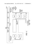
[0007]FIG. 1 This depicts the concept of installation of the INERTIAL SENSOR TRACKING SYSTEM in an underground mine, specifically a coal mine.
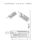
[0008]FIG. 2 This is the drawing of the INERTIAL SENSOR TRACKING SYSTEM Wireless Body Pack Transmitter inertial position transmitter.
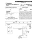
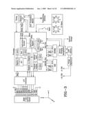
[0009]FIG. 3 This is a detailed block diagram of the INERTIAL SENSOR TRACKING SYSTEM Wireless Body Pack Transmitter.
[0010]FIG. 4 This illustrates the battery Charging and Master Reset Station; including geodetic survey monument locations with orthogonal orientation.
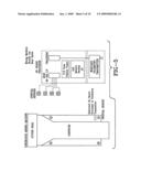
[0011]FIG. 5 This depicts inertial sensors located on mining machinery and the block diagram of connectivity for the Machinery Tracker.
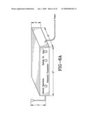
[0012]FIG. 6A This depicts the broadband Telemetry Transceiver.
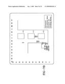
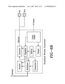
[0013]FIG. 6B This is a block diagram of the broadband wireless Telemetry Transceiver with hard wire capability.
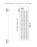
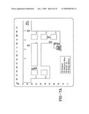
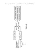
[0014]FIG. 7A This illustrates the computer monitor screen with active body pack Wireless Inertial Body Pack Transmitters and wireless inertial sensors on machinery showing the grid coordinate system of location.
[0015]FIG. 7B This illustrates the computer monitor screen, as in FIG. 4A, with magnification on a specific area of interest.
[0016]FIG. 8 This depicts the INERTIAL SENSOR TRACKING SYSTEM back up Emergency Power Distribution and power loss/switching indicating critical electrical busses.
DETAILED DESCRIPTION OF THE INVENTION
[0017]The INERTIAL SENSOR TRACKING SYSTEM is an underground mine personnel and machinery tracking system consisting of Wireless Body Pack Transmitters, Machinery Mounted Inertial Sensors, Telemetry Transceivers, Computer Equipment, Monitor Equipment, Specialized Software Applications, and Emergency Power Generation Equipment. FIG. 1 depicts the INERTIAL SENSOR TRACKING SYSTEM installed in an underground mine environment. FIG. 1 indicates the overall concept of the installation of the underground equipment.
The Wireless Body Pack Transmitter
[0018]The Wireless Body Pack Transmitter is an inertial sensing device and transmitter, powered by battery cells. FIG. 2 depicts the Wireless Body Pack Transmitter. This device is worn by the underground mine personnel, and transmits telemetric velocity data. The Wireless Body Pack Transmitter has indicators for BATTERY status, TRANSMIT/RECEIVE status, and a liquid crystal display. The device has a short neoprene titanium external antenna for radio frequency transmission and reception. The physical dimensions of the device are 6'' (height)×3'' (width)×2'' (depth).
[0019]The body pack contains the Micro-Electro-Mechanical Sensor (MEMS) inertial sensor. The sensor provides scaled outputs for Velocity North, Velocity East, Velocity Vertical, Gyro Rate X, Gyro Rate Y, and Gyro Rate Z. The velocity components are utilized to provide a means of tracking movement, from a known starting location. The body pack MEMS sensor is under the control of a Central Processing Unit (CPU) and operates in "Strap Down" inertial sensing mode. FIG. 3 depicts the detailed block diagram of the Wireless Body Pack Transmitter. The required inertial operating software and de-noising algorithms are contained in on board Electrically Erasable Programmable Read Only Memory (EEPROM). Proprietary software for mitigation of rate gyroscope drift is programmed into EEPROM. Extraction of inertial velocity information from random error velocity is accomplished by software sub-routine and is based on Skaloud algorithms (1999). Estimator and predictor probability algorithms are Kalman based and utilized to provide corrections to rate gyro drift and accelerometer output velocity error. Shuler error velocity compensation is accomplished by 3rd order Kalman damping. The MEM inertial sensor operates in "strap down" mode. Strap down mode is the operation of the inertial sensor without gimbal isolation or stabilized gimbal isolation to maintain accelerometer isolation from vertical acceleration.
[0020]Vertical acceleration is defined as the force of gravity, which is sensed by the accelerometer, in this instance. The MEM sensor is hard mounted to the chassis of the Wireless Body Pack Transmitter and senses three-dimensional velocity, as well as Roll, Pitch, and Azimuth angular rate components. Composite gyroscopic rotation and linear acceleration are processed by the on board micro-processor to maintain a computer model of a true and level sensor. A Direction Cosine Matrix is used to convert accelerometer velocities from velocity components to true velocities. Earth spin, Coriolis Correction, Earth Loop Error, and Shuler Oscillation Error are corrected with software. The MEM gyroscope data is compensated and corrected for bias, scale factor, linearity, misalignment error, and temperature. The corrected gyroscope rates represent all body motions with respect to inertial space. Earth rates and vehicle rates (the wireless body pack transmitter), are subtracted from the gyroscope rates to yield sensor rates with respect to an Earth fixed reference frame. The latter rates are then appropriately integrated to provide an Euler parameter and Direction Cosine representation of the MEM sensor attitude relative to a North, East, and Vertical reference frame. Velocity North, East, and Vertical, also known as velocity telemetric data, is processed and converted to TCP/IP format for transmission in packets to the broadband telemetry transceivers. An integrated radio frequency transmitter is located in the body pack and is frequency agile to provide the best data transmission, due to interference and low signal strength conditions. Upon transmission of packet data, an acknowledgment is returned from the broadband transceiver to the body pack to ensure accurate reception of the transmitted velocity data, commonly known as hand shake signal between data transmission and reception devices.
[0021]The Wireless Body Pack Transmitters are stored in a combination Charger and Master Reset station. The Charging and master Reset station provides two functions. FIG. 4 is the Charging and Master Reset Station, shown with the mechanical survey alignment monuments required for accurate positional installation. The charging function provides for the charging and re-charging of the body pack transmitter batteries for operation. The reset function provides a mechanically aligned location "home" location, which the main computer charting software utilizes to perform motion tracking and display of the sensor in each body pack. Mechanical alignment consists of placing geographic brass monuments in the underground mine and determining the precise location of the monuments based a GPS/Geodetic survey conducted outside the underground mine, using accepted land survey techniques. A body pack transmitter is considered "reset", or aligned to the home position, when located in the charger and reset station. Battery power for the wireless body pack is provided by a combination of Lithium Ion battery cells in an Intrinsically Safe container in the body pack. Battery charging cycle, discharge cycle, and deep discharge is under processor control of the central processor on board the wireless body pack. This sequence of events is referred to as "battery management."
[0022]The specific Lithium Ion battery cells are of Lithium Ferrous Phosphate, or LiFePO4, composition. This specific chemical composition is much less prone to thermal combustion and does not provide an oxidizer source to support combustion.
Machinery Tracker
[0023]Machinery tracking is accomplished by the installation of multiple inertial sensors on the mining machinery. The operation of the machinery tracking system is similar to the operation of the Wireless Body Pack Transmitters. FIG. 5 depicts the Machinery Tracker installed on a continuous mining machine. It consists of four inertial sensors mounted on the machine and interfaced to the on board processor via RS-422 serial interface. Normal power for the Machinery Tracker is derived from the electrical power to operate the machine. When power is lost, power automatically switches to an on board battery operated power supply. Battery power for the Machinery Tracker is provided by a combination of Lithium Ion battery cells in an Intrinsically Safe container in the hardened case, which houses the transceiver. The Intrinsically Safe container consists of Keviar and Titanium, with a vent to ensure pressure equalization.
Telemetry Transceiver
[0024]Reception of the telemetric velocity data is via broadband radio frequency transceivers, which operate on primary mine alternating current, and batteries when primary mine alternating current is unavailable. FIG. 6A depicts the elemetry Transceiver. The Telemetry Transceiver has indicators for BATTERY OPERATION, SYSTEM ON, and DATA (when active). The Telemetry Transceiver has a neoprene coated titanium external antenna for radio frequency transmission and reception. The dimensions are 12'' width)× 10'' (depth)×4'' (height) in a titanium hardened case.
[0025]Telemetric velocity data from each body pack transmitter, via broadband Telemetry Transceivers, is relayed to the main computer system, located away from the mine. FIG. 6B depicts the block diagram of the Telemetry Transceiver. The transmission and reception is under control of multiplexer circuitry. Data from the Wireless Body Pack Transmitters is converted to 802.11G specification protocol for relay out of the underground mine. The Telemetry Transceiver has standard shielded pair wired outputs, as an alternate method of connection. Normal RJ 45 connectors are replaced with military specification water proof connectors, i.e. Cannon, ITT. Power to operate the Telemetry Transceiver is from normal mine primary power and provides the required current to operate the device, under normal conditions and provide battery charging. When primary power loss occurs, the Telemetry Transceiver automatically switches to internal battery operation. Battery operation, charging cycle, discharge cycle, and deep discharge cycle is under micro processor control. Battery power for the transceiver is provided by a combination of Lithium Ion battery cells in an Intrinsically Safe container in the hardened case, which houses the transceiver. The Intrinsically Safe container consists of Kevlar and Titanium, with a vent to ensure pressure equalization.
Tracking and Display
[0026]Charting and tracking software, in grid format, resides on the main computer. FIG. 7A depicts an example of the monitor system with the grid coordinate overlay. This software translates the telemetric velocity data from the broadband transceivers to icons on the computer monitors, which indicate precise location of the body pack transmitters attached to the mine personnel operating underground. FIG. 7B depicts the "zoom in" monitor screen, with grid coordinate overlay. Grid locations are translated to precise geographic locations, to be used in the event of an emergency for surface drilling, as well as overlay on existing underground mine maps for locating trapped personnel.
Emergency Power
[0027]Primary power, i.e. all operating current, is normally de-energized in an underground mine, in the event of an emergency. FIG. 8 depicts the Emergency Power system. A back up power system consisting of a propane fueled generator (located away from the mine), automatic power bus switching circuitry, and software selectable "critical" circuits will provide power to critical bus powered transceivers and the main computer system, as required. This is necessary to preserve battery life of the transceivers providing location data of the trapped underground mine personnel. All components located in the underground mine are contained in explosion proof containers constructed of Kevlar and Titanium. Battery cells utilized in the body pack transmitters and broadband transceivers are of Lithium Ion technology. The specific Lithium Ion technology consists of Lithium Ferrous Phosphate chemical composition. This composition is less prone to catastrophic combustion as previous Lithium Cobalt Oxide technology. All connectors are water proof and explosion resistant. All cabling is stainless steel armored, water proof, and low smoke. Additionally, all cabling of 60 volt and higher are rated at a safety rating of 150% of the maximum current capacity of the conductors. The majority of the system components are Commercial Off-The Shelf (COTS). The COTS components are integrated with the hardened containers designed to provide maximum sustainability under adverse conditions. All COTS components are in Titanium containers and housings and properly grounded to provide maximum protection from explosion blast and extraneous radio frequency interference. The entire INERTIAL SENSOR TRACKING SYSTEM may be removed from an underground mine upon completion of mining operations and closure of the underground mine, for utilization in another underground mine.
User Contributions:
comments("1"); ?> comment_form("1"); ?>Inventors list |
Agents list |
Assignees list |
List by place |
Classification tree browser |
Top 100 Inventors |
Top 100 Agents |
Top 100 Assignees |
Usenet FAQ Index |
Documents |
Other FAQs |
User Contributions:
Comment about this patent or add new information about this topic:
Images included with this patent application:
 |  |
 |  |
 |  |
 |  |
 |  |
 |
| Similar patent applications: | |
| Date | Title |
|---|---|
| 2010-02-11 | Multiple sensor lighting system |
| 2011-01-20 | Item storage and tracking system |
| 2011-12-15 | Multilane vehicle tracking system |
| 2012-03-29 | Multi sensor position and orientation system |
| 2009-03-05 | Sensor node and sensor network system |
| New patent applications in this class: | |
| Date | Title |
|---|---|
| 2016-04-28 | Sensor system and alerting unit for sensing and verifying data related to a movement of an object |
| 2016-04-07 | Smart signal light |
| 2014-04-03 | Notification system for providing awareness of an interactive surface |
| 2013-07-04 | Device for displaying rotation speed of fan |
| 2013-06-27 | Server system for monitoring status of fans |
| Top Inventors for class "Communications: electrical" | |
| Rank | Inventor's name |
|---|---|
| 1 | Lowell L. Wood, Jr. |
| 2 | Roderick A. Hyde |
| 3 | Juan Manuel Cruz-Hernandez |
| 4 | John R. Tuttle |
| 5 | Jordin T. Kare |