Patent application title: TYPE OF POSITION-LIMITING MECHANISM PREVENTING SLIPPING OUT OF DRAWER
Inventors:
Min Li (Jiangsu, CN)
Assignees:
JiangSu TongRun Tool Cabinet Co., Ltd.
IPC8 Class: AA47B8816FI
USPC Class:
31233444
Class name: Horizontally movable (e.g., drawer) having guide assembly and particular stop means
Publication date: 2008-12-25
Patent application number: 20080315742
Inventors list |
Agents list |
Assignees list |
List by place |
Classification tree browser |
Top 100 Inventors |
Top 100 Agents |
Top 100 Assignees |
Usenet FAQ Index |
Documents |
Other FAQs |
Patent application title: TYPE OF POSITION-LIMITING MECHANISM PREVENTING SLIPPING OUT OF DRAWER
Inventors:
Min LI
Agents:
LADAS & PARRY
Assignees:
Jiangsu Tongrun Tool Cabinet Co., Ltd.
Origin: LOS ANGELES, CA US
IPC8 Class: AA47B8816FI
USPC Class:
31233444
Abstract:
This utility model relates to a type of position limiting mechanism
preventing slipping out of drawers, consisting of arresting pin, keyway,
self-plugging rivet, compression spring and control handle arranged in
strip shaped drawer handle plate groove, and position-limiting pinch
plate on box side board corresponding to keyway position. The arresting
pin is strip shaped and consists of round pin rod and pin flap with
shoulder. On the round pin rod, compression spring is fitted and on its
tail end, control handle is fixed. The keyway is strip shaped with a
round hole in the middle; at one outer side of its front end, an
installation buckle with position-limiting buckle groove is provided, and
on side face near the tail of the same side, fixed installation seat with
internal assembling hole is provided. For operation, when the drawer is
pushed inward, the pin flap will be automatically clamped. To open the
drawer, just pull handle in the reverse direction to drive arresting pin
to retreat from position-limiting buckle hole, realizing unlocking.
Owning to simple structure and easy processing of self-made parts,
manufacture cost is extremely low. In addition, installation and use are
easy, operation is reliable and safe, providing strong practicality.Claims:
1. A type of position-limiting mechanism preventing slipping out of
drawer, consisting of arresting pin (1), keyway (2), self-plugging rivet
(3), compression spring (4), control handle (5), and position-limiting
pinch plate (6), and characterized by that said arresting pin (1), keyway
(2), self-plugging rivet (3), compression spring (4), and control handle
(5) are provided in strip shaped drawer handle plate (20) groove (21),
and position-limiting pinch plate (6) fixed on side board of box (23) at
a position corresponding to edge of keyway (2) front round hole (9).
Among them:a. main body of arresting pin (1) is strip shaped and consists
of round pin rod (7) and shouldered pin flap (8) with wedge shaped front
part, with control handle (5) fitted on round pin rod (7) tail end
(24);b. main body of keyway (2) is strip shaped with round hole (9) in
the middle; on one outer side (11) of front end (10), protruding
installation buckle (13) with position-limiting buckle groove (12) is
provided. On the same side (11) near tail end (14), fixed mounting seat
(16) with internal assembling hole (15) is provided. On edge of tail end
round hole (9), internal clip shoulder (18) with mounting hole (17)
matching diameter of round pin rod (7) is provided;c. on
position-limiting pinch plate (6), position-limiting buckle hole (19) is
provided.
2. The position-limiting mechanism preventing slipping out of drawer of claim 1 wherein position-limiting buckle groove on said keyway (2) front protruding installation buckle (13) is buckled on side of drawer front panel (22).
3. The position-limiting mechanism preventing slipping out of drawer of claim 1 wherein said fixed mounting seat (16) is assembled on drawer front panel (22) via self-plugging rivet (3).
4. The position-limiting mechanism preventing slipping out of drawer of claim 1 wherein said arresting pin (1) extends through keyway (2) round hole (9) as a whole part.
5. The position-limiting mechanism preventing slipping out of drawer of claim 1 wherein position of said compression spring (4) is limited by shouldered pin flap (8) and the internal clip shoulder (18) on edge of keyway (2) tail end round hole (9), and this spring is fitted on round pin rod (7) of arresting pin (1).
Description:
TECHNICAL FIELD
[0001]This utility model relates to a position-limiting device, in particular a position-limiting mechanism that can prevent self-slipping out of drawer.
BACKGROUND OF THE INVENTION
[0002]At present, storage cabinets with drawers used on mobile tool box, automobiles and office desks are easy to use in unlocked status since drawers can be pulled out freely. However, such drawers are not resistant to shaking and will slip out easily. After slipping out of drawers, the whole cabinet may fall. This results in poor reliability and safety, hence such drawers are only applicable to stable environment. To prevent accidental slipping out of drawers and improve drawer safety, traditional method is to use lock and key mechanism to lock drawers. However, with this method, trouble may come from forgetting to lock drawers, leading to accident. In recent years, key-free drawer locking mechanism (against slipping out) appears on the market, eliminating this trouble and bringing about convenience. Such mechanism mostly has complicated structure and cost even exceeding cost of lock, hence is not satisfactory in terms of economy.
DETAILED DESCRIPTION
[0003]The purpose of this utility model is to provide a new position-limiting mechanism against slipping of drawer totally free of the trouble of use of key and of simple structure and low cost. This new mechanism can lock automatically and allow manual release of locking.
[0004]Drawer anti-slipping position-limiting mechanism of this utility mode mainly consists of arresting pin, keyway, self-plugging rivet, compression spring, control handle, and position-limiting pinch plate, and characterized by that said arresting pin, keyway, self-plugging rivet, compression spring, and control handle are provided in strip shaped drawer handle plate groove, and position-limiting pinch plate fixed on side board of box at a position corresponding to edge of keyway front round hole. Among them: said main body of arresting pin is strip shaped and consists of round pin rod and shouldered pin flap with wedge shaped front part, with said control handle fitted on round pin rod tail end; main body of said keyway is strip shaped with round hole in the middle; on one outer side of front end, protruding installation buckle with position-limiting buckle groove is provided. On the same side near tail end, fixed mounting seat with internal assembling hole is provided. On edge of tail end round hole, internal clip shoulder with mounting hole matching diameter of round pin rod is provided; on said position-limiting pinch plate, position-limiting buckle hole is provided.
[0005]In installed status, drawer anti-slipping position-limiting mechanism is provided in strip shaped drawer handle plate groove. Position-limiting buckle groove on said keyway front protruding installation buckle is buckled on side of drawer front panel, and fixed on the set position at box side of drawer panel via assembling hole on fixed mounting seat near tail end of keyway and self-plugging rivet. The arresting pin extends through middle round hole on keyway as a whole part. Position of compression spring is limited by shouldered pin flap and the internal clip shoulder on edge of keyway tail end round hole, and this spring is fitted on round pin rod of arresting pin. At the same time, a control handle is fixed on extended tail end of arresting pin round pin rod. Position-limiting pinch plate is fixed on box side board where its position-limiting buckle hole corresponds to position of keyway front round hole edge.
[0006]For operation, when not subject to external force, the compression spring is stretched, the control handle is clamped at keyway tail end, and under trust force toward keyway front round hole edge, the wedged shouldered pin flap of arresting pin extends outside. With drawer pulled out, wedge shaped shouldered pin flap on front end of arresting pin is in contact with position-limiting pinch plate on box side. When the drawer is fully pushed inward and wedge shaped shouldered pin flap is aligned with position-limiting buckle hole on position-limiting pinch plate, locking is automatic. To open the drawer, pull handle in reverse direction, so that the arresting pin moves and wedge shaped shouldered pin flap retreats from position-limiting buckle hole, unlocking the drawer.
[0007]In the drawer anti-slipping position-limiting mechanism of this utility model based on above design, since the driving force comes from compression spring control handle and the compression spring is fitted on round pin rod of arresting pin in position-limiting shaft mounted mode, during operation, this spring will stretch or compress in an automatic orderly manner, so that the spring will not break to affect reliability and safety. For installation, you only need to arrange a position-limiting notch on edge of drawer front panel and provide a position-limiting rivet hole on the panel to mechanism of this utility model in drawer handle plate groove. In addition, there are not many structural members, among them self-plugging rivet and compression spring are standard procured parts, and drawer handle plate and position-limiting pinch plate are basic members of drawer and box; only arresting pin, keyway and control handle are special parts to be fabricated. Further more, structure of such special parts is simple, and fabrication of is easy. Therefore, production cost is extremely low, even lower than cost of normal lock, installation and operation is easy, and operation is reliable and safe. This invention is especially suitable for drawers subject to movement and poor stability environment.
[0008]DESCRIPTION OF DRAWING FIGURES
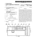
[0009]FIG. 1 is a schematic of basic structure of the preferred embodiment of this utility model;
[0010]FIG. 2 is A-A section view of FIG. 1;
[0011]FIG. 3 is B-B section view of FIG. 1;
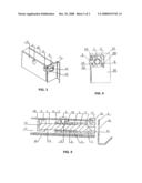
[0012]FIG. 4 is a schematic of installation status of the preferred embodiment of this utility model;
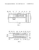
[0013]FIG. 5 is a schematic of working status (manual control) of the preferred embodiment of this utility model.
[0014]In these figures:
TABLE-US-00001 1. Arresting pin 2. Keyway 3. Self-plugging 4. Compression rivet spring 5. Control handle 6. Position-limiting 7. Round pin rod 8. Wedge shaped pinch plate shouldered pin flap 9. Round hole 10. Front end 11. Outer side 12. Position- limiting buckle groove 13. Installation 14. Tail end 15. Assembling 16. Fixed mounting buckle hole seat 17. Mounting hole 18. Internal clip 19. Position- 20. Drawer handle shoulder limiting buckle plate hole 21. " " groove 22. Drawer front 23. One side of box 24. Extended tail panel end
PREFERRED EMBODIMENT
[0015]The following further describes this utility model in combination with drawing figures and preferred embodiment.
[0016]In FIG. 1, FIG. 2, FIG. 3, FIG. 4 and FIG. 5, drawer anti-slipping position-limiting mechanism of this utility mode mainly consists of arresting pin 1, keyway 2, self-plugging rivet 3, compression spring 4, control handle 5, and position-limiting pinch plate 6. Among them: main body of arresting pin 1 is strip shaped and consists of round pin rod 7 and shouldered pin flap 8 with wedge shaped front part, with control handle 5 fitted on round pin rod 7 tail end 24; main body of keyway 2 is strip shaped with round hole 9 in the middle; on one outer side 11 of front end 10, protruding installation buckle 13 with position-limiting buckle groove 12 is provided. On the same side 11 near tail end 14, fixed mounting seat 16 with internal assembling hole 15 is provided. On edge of tail end round hole 9, internal clip shoulder 18 with mounting hole 17 matching diameter of round pin rod 7 is provided; on position-limiting pinch plate 6, position-limiting buckle hole 19 is provided.
[0017]In installed status, drawer anti-slipping position-limiting mechanism is provided in strip shaped drawer handle plate 20 groove 21. Position-limiting buckle groove 12 on keyway 2 front protruding installation buckle 13 is buckled on side of drawer front panel 22, and fixed on the set position at one side of box 23 of drawer panel 22 via assembling hole 15 on fixed mounting seat 16 near tail end of keyway 2 and self-plugging rivet 3. The arresting pin 1 extends through middle round hole 9 on keyway 2 as a whole part. Position of compression spring 4 is limited by shouldered pin flap 8 and the internal clip shoulder 18 on edge of keyway 2 tail end round hole 9, and this spring is fitted on round pin rod 7 of arresting pin 1. At the same time, a sliding control handle 5 is fixed on extended tail end 24 of arresting pin 1 round pin rod 7. Position-limiting pinch plate 6 is fixed on one side of box 23 where its position-limiting buckle hole 19 corresponds to position of keyway 2 front round hole 9 edge.
[0018]For operation, when not subject to external force, the compression spring 4 is stretched, the control handle 5 is clamped at keyway 2 tail end, and under trust force toward keyway 2 front round hole 9 edge, the wedged shouldered pin flap 8 of arresting pin 1 extends outside and can be locked. With drawer pulled out, wedge shaped shouldered pin flap 8 on front end of arresting pin 1 is in contact with position-limiting pinch plate 6 on box side board 23. When the drawer is fully pushed inward and wedge shaped shouldered pin flap 8 is aligned with position-limiting buckle hole 19 on position-limiting pinch plate 6, locking is automatic. To open the drawer, pull handle 5 in reverse direction, so that the arresting pin 1 moves and wedge shaped shouldered pin flap 8 retreats from position-limiting buckle hole 19, unlocking the drawer.
User Contributions:
comments("1"); ?> comment_form("1"); ?>Inventors list |
Agents list |
Assignees list |
List by place |
Classification tree browser |
Top 100 Inventors |
Top 100 Agents |
Top 100 Assignees |
Usenet FAQ Index |
Documents |
Other FAQs |
User Contributions:
Comment about this patent or add new information about this topic:
| People who visited this patent also read: | |
| Patent application number | Title |
|---|---|
| 20100086761 | LASER LIGHT TRANSMISSIVE RESIN MEMBER AND RESIN MOLDED PRODUCT MADE THEREOF |
| 20100086760 | Reinforced Silicone Resin Films |
| 20100086759 | Fitness and therapy mat for standing and walking |
| 20100086758 | FOAMED SHEET OF POLYLACTIC ACID RESIN, FOAM MOLDING OF POLYLACTIC ACID RESIN AND METHOD OF PREPARING FOAM MOLDING |
| 20100086757 | Method for coating a component |
Images included with this patent application:
 |  |
 |
| Similar patent applications: | |
| Date | Title |
|---|---|
| 2012-11-01 | Medical cart, medication module, height adjustment mechanism, and method of medicaton transport |
| 2010-12-30 | Cover mechanism for covering an opening of a housing |
| 2012-08-23 | Fixing mechanism of housing and fixing assembly thereof |
| 2010-02-04 | Automatic position restoring slide rail device |
| 2010-06-03 | Vending machine for dispensing cylindrical articles |
| New patent applications in this class: | |
| Date | Title |
|---|---|
| 2016-05-26 | Magnetic hooking device for movable parts of furniture |
| 2016-03-17 | Drawer slider |
| 2016-02-04 | Slide rail assembly |
| 2015-12-24 | Pull-out guide |
| 2015-11-19 | Structure to prevent drawer from falling off |
| New patent applications from these inventors: | |
| Date | Title |
|---|---|
| 2017-02-16 | Direct-current power transmission protection device, converter and protection method |
| Top Inventors for class "Supports: cabinet structure" | |
| Rank | Inventor's name |
|---|---|
| 1 | Yun-Lung Chen |
| 2 | Karl-Friedrich Laible |
| 3 | Jae Hoon Lim |
| 4 | Wen-Tang Peng |
| 5 | Chen-Lu Fan |