Patent application title: PARALLEL FLOW EVAPORATOR
Inventors:
Zongde Dong (Shanghai, CN)
IPC8 Class: AF28D706FI
USPC Class:
165176
Class name: With manifold type header or header plate inlet and outlet header means side by side
Publication date: 2008-12-25
Patent application number: 20080314575
Inventors list |
Agents list |
Assignees list |
List by place |
Classification tree browser |
Top 100 Inventors |
Top 100 Agents |
Top 100 Assignees |
Usenet FAQ Index |
Documents |
Other FAQs |
Patent application title: PARALLEL FLOW EVAPORATOR
Inventors:
Zongde Dong
Agents:
DORSEY & WHITNEY LLP;INTELLECTUAL PROPERTY DEPARTMENT
Assignees:
Origin: MINNEAPOLIS, MN US
IPC8 Class: AF28D706FI
USPC Class:
165176
Abstract:
A parallel flow evaporator comprises a transitional plate. A left side
plate and a right side plate are connected with two side edges of the
transitional plate respectively. A first liquid inlet manifold is secured
to an upper side edge of a forward side surface of said transitional
plate, a first gas outlet manifold is secured to an upper side edge of a
rearward side surface of said transitional plate, a second liquid inlet
manifold is secured to a lower side edge of the forward side surface of
said transitional plate, and a second gas outlet manifold is secured to a
lower side edge of the rearward side surface of said transitional plate.
A plurality of flat tubes, which are parallel with and distant from each
other, are arranged between said first liquid inlet manifold and said
second liquid inlet manifold. Said first liquid inlet manifold and said
second liquid inlet manifold as well as said first gas outlet manifold
and said second liquid inlet manifold communicate with said flat tubes.
Between the flat tubes there are arranged a plurality of fins. A left end
of the second liquid inlet manifold is connected with a coolant inlet and
a left end of the second gas outlet manifold is connected with a coolant
outlet. According to the present invention, flat tubes and fins are
provided in the parallel flow evaporator, and the liquid inlet manifolds
and the gas outlet manifolds are designed as U-tubes, so the heat
exchange efficiency of the parallel flow evaporator is improved.Claims:
1. A parallel flow evaporator comprising a transitional plate, wherein a
left side plate is secured vertically to a left side edge of said
transitional plate, a right side plate is secured vertically to a right
side edge of said transitional plate, a first liquid inlet manifold is
secured to an upper side edge of a forward side surface of said
transitional plate, a first gas outlet manifold is secured to an upper
side edge of a rearward side surface of said transitional plate, a second
liquid inlet manifold is secured to a lower side edge of the forward side
surface of said transitional plate, and a second gas outlet manifold is
secured to a lower side edge of the rearward side surface of said
transitional plate; said first liquid inlet manifold, said first gas
outlet manifold, said second liquid inlet manifold and said second gas
outlet manifold are parallel with each other; a plurality of flat tubes,
which are parallel with and distant from each other, are arranged between
said first liquid inlet manifold and said second liquid inlet manifold;
said first liquid inlet manifold and said second liquid inlet manifold
communicate with said flat tube; said first gas outlet manifold and said
second liquid inlet manifold communicate with said flat tubes; between
the flat tubes there are arranged a plurality of fins; a left end of the
second liquid inlet manifold is connected with a coolant inlet and a
right end of the second liquid inlet manifold is closed; a left end of
the second gas outlet manifold is connected with a coolant outlet and a
right end of the second gas outlet manifold is closed; a first partition,
a second partition, a third partition and a fourth partition are provided
in the second liquid inlet manifold sequentially from right to left, the
partitions being perpendicular to an axis of the second liquid inlet
manifold and distant from each other; said first partition is provided
with one through hole, said second partition is provided with two through
holes, and said third partition is provided with three through holes.
2. The parallel flow evaporator according to claim 1, wherein both of said coolant inlet and said coolant outlet are provided on a pressing plate, and said pressing plate is connected with the left side plate.
3. The parallel flow evaporator according to claim 1, wherein each of the first liquid inlet manifold, the first gas outlet manifold, the second liquid inlet manifold and the second gas outlet manifold is U-shaped in cross-section.
Description:
FIELD OF THE INVENTION
[0001]This invention relates to the field of mechanics, especially to a heat exchange machinery, more especially to a heat exchanger, particularly a parallel evaporator, which is used in an air conditioner of an automobile.
BACKGROUND OF THE INVENTION
[0002]In the prior art, a heat exchanger used in an air conditioner of an automobile is consisted of a plurality of evaporators connected in series. This results in that the air conditioner is bulky and heavy, which increases the load of the automobile. Furthermore, the efficiency of the heat exchange is low and it is hard to save energy.
SUMMARY OF THE INVENTION
[0003]An object of the present invention is to provide a parallel flow evaporator, which can overcome the deficiencies of the prior art automobile air conditioner that the efficiency of heat exchange is low and it is hard to save energy.
[0004]The parallel flow evaporator of the present invention comprises a transitional plate, wherein a left side plate is secured vertically to a left side edge of said transitional plate, a right side plate is secured vertically to a right side edge of said transitional plate, a first liquid inlet manifold is secured to an upper side edge of a forward side surface of said transitional plate, a first gas outlet manifold is secured to an upper side edge of a rearward side surface of said transitional plate, a second liquid inlet manifold is secured to a lower side edge of the forward side surface of said transitional plate, and a second gas outlet manifold is secured to a lower side edge of the rearward side surface of said transitional plate; said first liquid inlet manifold, said first gas outlet manifold, said second liquid inlet manifold and said second gas outlet manifold are parallel with each other; a plurality of flat tubes, which are parallel with and distant from each other, are arranged between said first liquid inlet manifold and said second liquid inlet manifold; said first liquid inlet manifold and said second liquid inlet manifold communicate with said flat tubes; said first gas outlet manifold and said second liquid inlet manifold communicate with said flat tubes; between the flat tubes there are arranged a plurality of fins; a left end of the second liquid inlet manifold is connected with a coolant inlet and a right end of the second liquid inlet manifold is closed; a left end of the second gas outlet manifold is connected with a coolant outlet and a right end of the second gas outlet manifold is closed; a first partition, a second partition, a third partition and a fourth partition are provided in the second liquid inlet manifold sequentially from right to left, the partitions being perpendicular to an axis of the second liquid inlet manifold and distant from each other; said first partition is provided with one through hole, said second partition is provided with two through holes, and said third partition is provided with three through holes.
[0005]Furthermore, both of said coolant inlet and said coolant outlet are provided on a pressing plate, and said pressing plate is connected with the left side plate.
[0006]Still furthermore, each of the first liquid inlet manifold, the first gas outlet manifold, the second liquid inlet manifold and the second gas outlet manifold is U-shaped in cross-section.
[0007]The principle of the present invention is as follows: liquid coolant enters the second liquid inlet manifold through the coolant inlet, then flows through the flat tubes to effect heat exchange, and thus turns into gas coolant; after flowing through the first liquid inlet manifold and the first gas outlet manifold, the gas coolant enters the second gas outlet manifold and is discharged through the coolant outlet. The flat tubes facilitate efficient heat exchange of the coolant with the environment, and the fins between the flat tubes increase the area of heat transfer, so that the heat exchange efficiency is improved. With the cross sections of the liquid inlet manifolds and the gas outlet manifolds being U-shaped, the flow resistance is reduced.
[0008]Compared with the prior art, the effects of the present invention are positive and obvious. According to the present invention, flat tubes and fins are provided in the parallel flow evaporator, and the liquid inlet manifolds and the gas outlet manifolds are designed as U-tubes, so the heat exchange efficiency of the parallel flow evaporator is improved.
BRIEF DESCRIPTION OF THE DRAWINGS
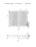
[0009]FIG. 1 is a front schematic view of a parallel flow evaporator of the present invention;
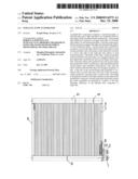
[0010]FIG. 2 is a bottom schematic view of a parallel flow evaporator of the present invention;
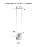
[0011]FIG. 3 is a left schematic view of a parallel flow evaporator of the present invention.
DETAILED DESCRIPTION OF THE INVENTION
[0012]As shown in FIGS. 1, 2 and 3, the parallel flow evaporator of the present invention comprises a transitional plate 12, wherein a left side plate 5 is secured vertically to a left side edge of said transitional plate 12, a right side plate 6 is secured vertically to a right side edge of said transitional plate 12, a first liquid inlet manifold 13 is secured to an upper side edge of a forward side surface of said transitional plate 12, a first gas outlet manifold 14 is secured to an upper side edge of a rearward side surface of said transitional plate 12, a second liquid inlet manifold 3 is secured to a lower side edge of the forward side surface of said transitional plate 12, and a second gas outlet manifold 4 is secured to a lower side edge of the rearward side surface of said transitional plate 12; said first liquid inlet manifold 13, said first gas outlet manifold 14, said second liquid inlet manifold 3 and said second gas outlet manifold 4 are parallel with each other; a plurality of flat tubes 7, which are parallel with and distant from each other, are arranged between said first liquid inlet manifold 13 and said second liquid inlet manifold 3; said first liquid inlet manifold 13 and said second liquid inlet manifold 3 communicate with said flat tube 7; said first gas outlet manifold 14 and said second liquid inlet manifold 3 communicate with said flat tubes 7; between the flat tubes 7 there are arranged a plurality of fins 8; a left end of the second liquid inlet manifold 3 is connected with a coolant inlet 1 and a right end of the second liquid inlet manifold 3 is closed; a left end of the second gas outlet manifold 4 is connected with a coolant outlet 2 and a right end of the second gas outlet manifold 4 is closed; a first partition 15, a second partition 16, a third partition 17 and a fourth partition 9 are provided in the second liquid inlet manifold 3 sequentially from right to left, the partitions being perpendicular to an axis of the second liquid inlet manifold 3 and distant from each other; said first partition 15 is provided with one through hole, said second partition 16 is provided with two through holes, and said third partition 17 is provided with three through holes.
[0013]Furthermore, both of said coolant inlet 1 and said coolant outlet 2 are provided on a pressing plate 11, and said pressing plate 11 is connected with the left side plate 5. A connecting plate 10 is provided between the pressing plate 11 and the left side plate 5.
[0014]Still furthermore, each of the first liquid inlet manifold 13, the first gas outlet manifold 14, the second liquid inlet manifold 3 and the second gas outlet manifold 4 is U-shaped in cross-section.
User Contributions:
comments("1"); ?> comment_form("1"); ?>Inventors list |
Agents list |
Assignees list |
List by place |
Classification tree browser |
Top 100 Inventors |
Top 100 Agents |
Top 100 Assignees |
Usenet FAQ Index |
Documents |
Other FAQs |
User Contributions:
Comment about this patent or add new information about this topic:
| People who visited this patent also read: | |
| Patent application number | Title |
|---|---|
| 20130027578 | IMAGING SYSTEMS WITH DIGITALLY CONTROLLED ANALOG OFFSET COMPENSATION |
| 20130027577 | IMAGING SYSTEMS WITH COLOR FILTER BARRIERS |
| 20130027576 | METHOD AND SYSTEM FOR DIGITAL PULSE RECOGNITION DEMODULATION |
| 20130027575 | METHOD AND APPARATUS FOR ARRAY CAMERA PIXEL READOUT |
| 20130027574 | METHOD AND APPARATUS FOR VERIFICATION OF IMAGING SYSTEMS |
Images included with this patent application:
 |  |
 |
| Similar patent applications: | |
| Date | Title |
|---|---|
| 2010-09-02 | Parallel flow evaporator with spiral inlet manifold |
| 2011-02-24 | Parallel flow evaporator with spiral inlet manifold |
| 2009-04-09 | Twist vane counter-parallel flow heat exchanger apparatus and method |
| 2008-12-04 | Parallel flow heat exchanger for heat pump applications |
| 2009-05-21 | Air and coolant circuit configurations and control of fuel cell systems as power source in automotive, stationary, and portable applications |
| New patent applications in this class: | |
| Date | Title |
|---|---|
| 2014-04-03 | Heat exchanger and production method thereof |
| 2013-09-19 | Manifold fluid communication plate |
| 2013-09-19 | Manifold fluid communication plate |
| 2011-04-21 | Manifold fluid communication plate |
| 2009-09-24 | Heat exchanger |
| Top Inventors for class "Heat exchange" | |
| Rank | Inventor's name |
|---|---|
| 1 | Levi A. Campbell |
| 2 | Chun-Chi Chen |
| 3 | Tai-Her Yang |
| 4 | Robert E. Simons |
| 5 | Richard C. Chu |