Patent application title: Method and Plant for Printing a Chain of Warp Yarns
Inventors:
Claudio Gherardi (Milano, IT)
Francesco Azzimonti (Busto Arsizio (varese), IT)
Elisabetta Monti (Rovello Porro (como), IT)
Assignees:
GHERTEX S.R.L.
IPC8 Class: AD06B100FI
USPC Class:
68205 R
Class name: Machines liquid applying tricklers and sprinklers
Publication date: 2008-12-25
Patent application number: 20080314091
Inventors list |
Agents list |
Assignees list |
List by place |
Classification tree browser |
Top 100 Inventors |
Top 100 Agents |
Top 100 Assignees |
Usenet FAQ Index |
Documents |
Other FAQs |
Patent application title: Method and Plant for Printing a Chain of Warp Yarns
Inventors:
Claudio Gherardi
Francesco Azzimonti
Elisabetta Monti
Agents:
OBLON, SPIVAK, MCCLELLAND MAIER & NEUSTADT, P.C.
Assignees:
GHERTEX S.R.L.
Origin: ALEXANDRIA, VA US
IPC8 Class: AD06B100FI
USPC Class:
68205 R
Abstract:
An anchorage guide for a trocar including a tubular body, formed by a
plurality of substantially circular sectors, radially moveable from and
towards the longitudinal axis of the tubular body between a first
position, at which the circular sectors flank each other according to a
first substantially circular arrangement with a diameter equal to that of
the tubular body, and a second position, at which the circular sectors
result equidistant from each other according to a second substantially
circular arrangement of greater diameter than that of the first
arrangement. Each of the circular sectors is rotatably connected to a
support element and a manual operation mechanism, moveably connected to
the support element, moves the circular sectors from the first to the
second position and vice versa.Claims:
1-33. (canceled)
34. A method for printing a chain of warp yarns by spraying ink onto the chain of yarns to produce thereon a predetermined decorative motif, the method comprising:unwinding the chain of warp yarns from a first beam;measuring tension of the chain yarns, and regulating their tensioning to maintain the tensioning within a predetermined range;depositing the chain of warp yarns parallel with each other on an adhesive belt;guiding the chain of warp yarns to a plotter;spraying ink by the plotter;rewinding the chain of warp yarns on a second beam; andfeeding the second beam to a loom to weave the printing chain of warp yarns with weft yarns to obtain a fabric.
35. A method as claimed in claim 34, wherein after receiving the ink the yarn chain is dried, and before the spraying ink, the yarn chain is impregnated with a product facilitating ink absorption.
36. A method as claimed in claim 35, wherein the yarn chain is impregnated by immersion in a tank containing the product, and after immersion, the yarn chain is subjected to wringing, and after the wringing, the yarn chain is dried.
37. A method as claimed in claim 36, wherein the measuring the tension of the chain yarns is made before their impregnation.
38. A method as claimed in claim 36, wherein the measuring the tension of the chain yarns is made after the drying.
39. A plant for printing a chain of warp yarns, comprising:means for feeding the yarn chain to an ink application device including means for spraying ink onto the chain to reproduce a predetermined motif;a first beam where the chain of warp yarns are wound, the first beam housed on a support rotatable by a first motor;a first sensor disposed downstream of the first beam, for measuring tension of the chain yarns to controlling their tensioning to maintain the tensioning within a predetermined range;an adhesive belt for conveying the chain of warp yarns parallel with each other from the first beam to the means for spraying ink, the adhesive belt being operable by at least one second motor;the means for spraying ink including a plotter of ink jet type; anda second beam where the chain of warp yarns are rewound.
40. A plant as claimed in claim 39, wherein the first motor and second motor are connected to a plant operation control unit.
41. A plant as claimed in claim 39, wherein the second motor is connected to the plotter that controls its operation, the plotter being connected to a plant operation control unit and to a PC for transmitting all data relative to the printing.
42. A plant as claimed in claim 39, further comprising a drying device, positioned downstream of the plotter, to dry the portions of chain yarns leaving the plotter.
43. A plant as claimed in claim 39, further comprising, upstream of the plotter, a yarn chain impregnation device for impregnating the yarns with a product facilitating ink absorption, by including, downstream of the impregnation device, a wringing device for removing any excess product from the chain yarns, and wherein the wringing device includes a pair of rollers rotatable by at least one third motor connected to a plant operation control unit, the rollers being mutually associated along one of their generating lines such that during operation, the chain yarns are pressed between the mutually associated rollers.
44. A plant as claimed in claim 43, further comprising, for measuring the tension of the chain yarns, a second sensor disposed upstream of the impregnation device, the second sensor being connected to a plant operation control unit.
45. A plant as claimed in claim 43, further comprising a drying device positioned downstream of the wringing device.
46. A plant as claimed claim 45, wherein the first sensor is positioned downstream of the drying device.
47. A plant as claimed claim 40, wherein the first sensor is connected to the plant operation control unit.
48. A plant as claimed claim 39, wherein the second beam is housed on a support rotatable by a fourth motor connected to a tension measuring sensor.
49. A plant as claimed in claim 43, wherein the impregnation device includes a roller over which the chain yarns slide, the roller being immersed in the impregnating product and entraining the impregnating product during rotation, to wet the chain yarns.
50. A plant as claimed in claim 43, wherein the impregnation device includes fixed or movable spray nozzles that spray the impregnating product onto the chain yarns.
51. A plant as claimed in claim 39, wherein the first sensor is connected to the first motor.
52. A plant as claimed claim 43, further comprising:software for controlling the plant and including means for controlling printing by the means for spraying ink and regulator means for operating the first, the second, and the third motors feeding the chain yarns from the first beam to the means for spraying ink in relation to a printing speed of the means for spraying ink;a second chain yarn tension sensor disposed upstream of the impregnation device, the software presenting means for acquiring, from the second sensor, values indicative of the tension of the chain yarns; andmeans for regulating the speed of at least the second and third motors, to maintain the tension measured by the second sensor within a predetermined range.
53. A plant as claimed in claim 52, wherein the software further comprises means for acquiring, from the first sensor, values indicative of the tension chain yarns, and means for regulating the speed of at least the second motor, to maintain the tension measured by the first sensor within a predetermined range.
Description:
[0001]The present invention relates to a method and plant for printing a
chain of warp yarns, the method and plant of the invention in particular
being arranged to form chine'fabrics.
[0002]Fabrics are composed of warp yarns woven with weft yarns; the totality of warp yarns (not yet woven with weft yarns) is known as a chain.
[0003]Chine' fabrics in particular present decorative motifs which appear with confused jagged edges as they are formed by printing the decorative motifs not on the fabric, but only on the warp (i.e. by printing only on the chain prior to forming the fabric).
[0004]In the traditional method of forming chine' fabrics, the chain (i.e. the totality of warp yarns) is previously fed to a loom to form a fabric presenting very few wefts per centimetre, to obtain a fabric presenting characteristics similar to those of a gauze.
[0005]This fabric is fed to a printing table of traditional type to form the desired decorative motifs thereon.
[0006]After printing, steaming is carried out to fix the printed colour to the fibres, followed by washing to eliminate the excess colour.
[0007]After these operations, the weft yarns are extracted manually from the fabric in a discontinuous manner (usually 50 centimetres at a time), the released chain portions (i.e. The warp yarns) then being rewound on a warp beam.
[0008]The warp beam can then be fed to a loom to weave the previously printed chain yarns with new weft yarns (very densely) and form a fabric (by using the already printed chain and non-printed weft yarns).
[0009]During weaving the chain yarns tend to shift slightly one relative to another to generate the desired shading effect with confused jagged edges.
[0010]However the described traditional method is extremely lengthy, complicated and costly to implement as it involves prior formation of the fabric to be printed, then removal of the weft yarns and rewinding of the warp yarns on a warp beam.
[0011]This method is also discontinuous and manual (proceeding in about 50 centimetre steps), resulting in lengthy dead periods and consequent limited production.
[0012]The traditional method also requires the preparation of print frames or paper representing the motif to be transferred onto the chain by thermal transfer; the costs and commitment that this involves make the use of this method very uneconomical, especially for limited production.
[0013]In particular, the process of thermal transfer onto warp yarns from suitably prepared paper is extremely costly because it requires the preparation of several metres of paper, or alternatively it can be implemented using just a small quantity of paper, but this is extremely costly. Moreover the finished product formed in this manner presents very poor print quality and lacks design exclusivity. All this means that sampling in particular cannot be organized easily or economically.
[0014]The technical aim of the present invention is therefore to provide a method and plant for printing a chain of warp yarns which enable the stated drawbacks of the known art to be eliminated.
[0015]Within the scope of this technical aim, an object of the invention is to provide a method and plant with which chine' fabric can be produced more quickly and at lower cost than in the known art.
[0016]In particular, the method and plant of the invention do not require the formation of fabric to be printed by traditional methods, from which the weft yarns are then removed to obtain the printed chain.
[0017]Another object of the invention is to provide a method and plant which enable chine' fabric to be produced continuously and which present very high productivity.
[0018]A further object of the present invention is to provide a method and plant which do not require the provision of print frames or paper reproducing the motifs to be thermally transferred onto the chain.
[0019]This makes the production of chine' fabrics extremely flexible, rapid and economical, even when limited production is required.
[0020]The technical aim, together with these and further objects, are attained according to the invention by providing a method and plant for printing a chain of warp yarns in accordance with the accompanying claims.
[0021]Advantageously, the finished product obtained using the method and plant of the invention presents very high printing quality and, at the same time, high flexibility in producing the designs.
[0022]Moreover with the method and plant of the invention sampling can be organized easily and economically.
[0023]Further characteristics and advantages of the invention will be more apparent from the description of a preferred but non-exclusive embodiment of the method and plant for printing a chain of warp yarns according to the invention, illustrated by way of non-limiting example in the accompanying drawings, in which:
[0024]FIG. 1 is a schematic view of a plant according to the invention;
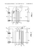
[0025]FIGS. 2 and 3 are two different embodiments of the plant of the invention for processing a chain the yarns of which have been previously treated to undergo preparation to receive ink and, respectively, for preparing the chain to receive ink; and
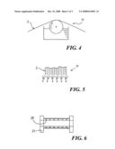
[0026]FIGS. 4, 5 and 6 show a detail of three different embodiments of a chain impregnation device.
[0027]The method for printing a chain of warp yarns according to the invention consists of spaying ink onto the yarn chain by a plotter, to form a predetermined decorative motif thereon; "ink" means any colouring product which is sprayed onto the yarn chain.
[0028]After receiving the ink, the yarn chain is dried, whereas before spraying ink the yarn chain is impregnated with a product facilitating ink absorption.
[0029]Preferably the yarn chain is impregnated by immersion in a tank containing the impregnating product, after which the yarn chain is wrung out.
[0030]After wringing, the yarn chain is dried.
[0031]During the impregnation and wringing operations the tension of the chain yarns varies, the tension being maintained under control to ensure production quality. For this purpose the tension of the chain yarns is measured before their impregnation, their tensioning then being regulated to maintain it within a predetermined range.
[0032]Drying can also influence the chain yarn tension, consequently the method also includes measuring the tension of the chain yarns 3 after drying, and regulating their tensioning to maintain it within a predetermined range.
[0033]The tension is suitably regulated by monitoring the average of the tensions in the chain yarns, measured before impregnation and after drying.
[0034]Advantageously , the yarn chain is unwound from a support and s prayed with ink continuously.
[0035]The present invention also relates to a plant for printing a chain of warp yarns, which is indicated overall by the reference numeral 1.
[0036]The plant 1 comprises means 2 for feeding the yarn chain 3 to an ink application device 4 comprising an ink jet plotter as the ink spray means.
[0037]The plant 1 also comprises an adhesive belt 5 for carrying the yarn chain 3 to the plotter 4.
[0038]The adhesive belt 5 is operated by a first motor 6 connected to the plotter 4 which controls its operation, the plotter being connected to a plant operation control unit 7 and to a PC for transmitting all data relative to the printing (e.g. shapes and colours).
[0039]The plant also comprises a drying device 9, positioned downstream of the plotter 4, to dry the chain yarn portions leaving the plotter 4.
[0040]Upstream of the plotter 4 there is a device 11 for impregnating the yarns of the chain 3; it impregnates the yarns with a product (of known type) for facilitating ink absorption.
[0041]In a first embodiment (for reactive dyes), the product consists of a mixture prepared by mixing 100 grams/litre of urea with 20 grams/litre of liquid oxidol (anti-reducing agent) and 20 grams/litre of sodium bicarbonate. 10 litres of water are then prepared, to which there are added (by spray-mixing) 100 grams/litre of "alginate ALG 30 MB" produced by D.A.T.T. Chimica and 10 grams/litre of tersene hexaliquid sequestrant (in water) and 10 grams/litre of imbibing agent.
[0042]In a second embodiment (for acid dyes), the product consists of a mixture prepared by mixing 30 grams/litre of urea with 30 grams/litre of "acidat" produced by D.A.T.T. Chimica. 10 litres of water are then prepared, to which there are added (by spray-mixing) 100 grams/litre of "my program SN 12 AZ" and 10 grams/litre of "diaselin RB" imbibing agent.
[0043]The impregnation device 11 consists in the illustrated example of a tank containing the impregnating product into which the chain 3 is immersed. Downstream of the impregnation device 11 the plant presents a wringing device 12 for removing any excess of impregnating product from the yarns of the chain 3.
[0044]The wringing device 12 comprises a pair of rollers 13 rotatable by a second motor 14 connected to a unit 7 for controlling plant operation.
[0045]The rollers 13 are mutually associated (at 15) along one of their generating lines, so that during operation the yarns of the chain 3 are pressed between the mutually associated rollers 13.
[0046]To control the tension of the chain yarns the plant presents a first sensor 17 for measuring the tension of the yarns of the chain 3.
[0047]The sensor 17 is disposed upstream of the impregnation device 11 and is connected to the plant operation control unit 7.
[0048]The plant 1 also presents a drying device 19 positioned downstream of the wringing device 12; it dries the chain yarns after they have been immersed in the impregnating product, so that they are ready to receive the ink.
[0049]The plant 1 also presents a seconds sensor 20 for measuring the tension of the yarns of the chain 3; this second sensor 20 is positioned downstream of the drying device 19 and is connected to the plant operation control unit 7.
[0050]The feed means 2 comprise a support rotatable by a third motor 22; a beam 21 for feeding the chain yarns 3 to be processed can be housed on this support.
[0051]The third motor 22 is also connected to the plant operation control unit 7.
[0052]The plant also comprises a discharge support rotatable by a fourth motor 25, this discharge support housing a discharge beam on which the chain yarns 3 are rewound after processing.
[0053]The motor 25 is controlled by a sensor 26 disposed downstream of the plotter 4 (the motor 25 although independent presents friction deriving from the sensor 26 in the form of a feeler); the sensor 26 measures the tension of the chain yarns and regulates the speed of the motor 25 to maintain this tension within a predetermined range.
[0054]The operation of the plant of the invention is apparent from that described and illustrated and is substantially as follows.
[0055]The chain yarns 3 are unwound from the beam 21 and pass by the first sensor 17 where their tension is measured; the chain yarns are then immersed in the tank 11 where they are impregnated with impregnating product.
[0056]The chain yarns 3 then pass between the rollers 13 where excess product is removed.
[0057]The chain yarns 3 then pass through the dryer 19 where they are perfectly dried and prepared to receive the ink.
[0058]At this point the sensor 20 measures the tension of the chain yarns 3 and transmits it to the control unit to enable the control unit 7 to regulate the plant on the basis of the average of the tensions measured by the first and second sensor 17, 20.
[0059]The chain yarns 3 are then deposited on the adhesive belt 5 which guides them to the plotter 4 where they receive the ink, and after drying through the dryer 9 are rewound onto the beam 23.
[0060]Hence in practice the method of the invention enables just the chain yarns themselves to be printed continuously without the need to produce a fabric to be printed and from which the weft yarns have then to be removed to obtain the warp yarns (to be wound on a beam to obtain a printed chain).
[0061]The present invention also relates to software for controlling the plant printing the chain of warp yarns.
[0062]The software comprises means for controlling printing by the plotter 4 and regulator means for operating the first and second motor 6, 14 feeding the chain yarns 3 from the feed beam 21 to the plotter 4 in relation to the plotter printing speed.
[0063]The software also presents means for acquiring (from the first sensor 17 and from the second sensor 20) those values indicative of the tension of the chain yarns 3 and means for regulating the speed at least of the second motor 14, to maintain the tension measured by the first and second sensor 17, 20 within a predetermined range.
[0064]The software also comprises means for regulating the speed at least of the first motor 6 to maintain the tension measured by the second sensor 20 within a predetermined range.
[0065]Modifications and variants in addition to those already stated are possible, for example FIG. 2 shows an embodiment of the plant particularly suitable to be fed with pre-impregnated chain yarns. i.e. having undergone impregnation before being placed on the machine.
[0066]In this case the plant comprises a yarn feeder composed of a yarn tension sensor 50 (for example equal to the sensor 20) connected to the motor 22 operating the beam 21, the adhesive belt 5, the plotter 4 and the dryer 9.
[0067]It should be noted that in this embodiment the second sensor 20 controls the chain yarns to ensure processing quality
[0068]The chain yarns 3 can be prepared by the device of FIG. 3, which comprises the impregnation device, the wringing device and the drying device, followed by rewinding the chain yarns on the discharge beam 23.
[0069]FIG. 4 shows a different embodiment of the impregnation device; this comprises a roller over which the chain yarns slide; this roller is immersed in the impregnating product and entrains it during its rotation, to wet the chain yarns.
[0070]FIG. 5 shows an embodiment of the impregnation device provided with fixed or movable spray nozzles which spray the impregnating product onto the chain yarns.
[0071]FIG. 6 shows a beam about which the chain yarns are wound, and having a body provided with a plurality of through holes 28; this beam (with the chain yarns wound thereon)) is inserted into a suitable tank from which the impregnating product passes into the beam through the holes 28, then passes to the outside of the beam, so that in passing through the beam the impregnating product wets the chain yarns.
[0072]The method and plant of the invention can also be conveniently used together with the (known) delave' process.
[0073]It has been found that traditional delave' treatment with resins is useful and is advantageously usable in preparing chain yarns or fabrics or yarns which are to be decorated by a plotter.
[0074]For this purpose the chain yarns are immersed in mixtures of cationic resins (of known type for the delave' process) and water.
[0075]For example, 30 grams/litre of the cationic resin "fissat tx" produced by the firm Bozzetto are mixed with water; the chain yarns are immersed in this mixture in known manner.
[0076]Depending on the required results, the quantity of resin mixed with water can vary by ±50%; the utilization range is at least between 5 and 95 grams/litre (grams of resin per litre of water).
[0077]The impregnating product contained in the tank 11 is hence (in this case) the described cationic resin mixture.
[0078]The cationic resin mixture can also be used in the plant of FIG. 3 to produce yarns to be wound on a beam.
[0079]It has been found that impregnating the yarns by the delave' process gives excellent results when the yarns are of vegetable fibre (for example cotton or linen) or animal fibre (wool-cashmere-silk).
[0080]Moreover, with both vegetable fibres and animal fibres, the delave' impregnation enables particularly brilliant colours to be obtained on the yarns (and hence on the finished fabric), this being useful for forming particular decorative motifs (this is true especially for cotton and linen).
[0081]It has also been surprisingly discovered that the delave' treatment with cationic resins can be implemented on any type of fabric or yarn, as preparatory treatment allowing subsequent printing of fabrics or yarns by a plotter.
[0082]The delave' process can also be implemented directly during preparation of the yarn in dyeing machines to hence prepare a beam carrying chain yarns ready for printing (hence without the need to immerse the chain yarns in the bath containing the impregnation product).
[0083]It has been found in practice that the method and plant for printing a chain of warp yarns according to the invention are particularly advantageous because they enable chine' fabric to be produced very quickly at very low cost; they also enable a very limited production to be achieved quickly at low cost.
[0084]The method and plant for printing a chain of warp yarns conceived in this manner are susceptible to numerous modifications and variants, all falling within the scope of the inventive concept; moreover all details can be replaced by technically equivalent elements.
[0085]In practice the materials used and the dimensions can be chosen at will according to requirements and to the state of the art.
User Contributions:
comments("1"); ?> comment_form("1"); ?>Inventors list |
Agents list |
Assignees list |
List by place |
Classification tree browser |
Top 100 Inventors |
Top 100 Agents |
Top 100 Assignees |
Usenet FAQ Index |
Documents |
Other FAQs |
User Contributions:
Comment about this patent or add new information about this topic:
Images included with this patent application:
 |  |
 |  |
| Similar patent applications: | |
| Date | Title |
|---|---|
| 2009-06-25 | Methods and systems for water delivery in an additive dispenser |
| 2012-12-06 | Apparatus and system for rotating elements in an appliance |
| 2012-04-12 | Laundry appliance for washing small quantities of clothing |
| 2010-06-03 | Washer/dryer with a light source inside a baffle for illuminating the drum |
| 2012-03-29 | Apparatus and method for determining a characteristic of a consumable |
| New patent applications in this class: | |
| Date | Title |
|---|---|
| 2010-01-07 | Washing machine |
| New patent applications from these inventors: | |
| Date | Title |
|---|---|
| 2011-05-12 | Machine for making fabrics comprising yarns decorated with pearls and fabric comprising yarns decorated with pearls |
| Top Inventors for class "Textiles: fluid treating apparatus" | |
| Rank | Inventor's name |
|---|---|
| 1 | Doo Young Ryu |
| 2 | Ig Geun Kwon |
| 3 | Sang Yeon Pyo |
| 4 | Dong Won Kim |
| 5 | Jae Ryong Park |