Patent application title: Inflatable Protection Valve
Inventors:
David Schuller (Casablanca, MA)
Assignees:
RXR Protect
IPC8 Class: AA41D1300FI
USPC Class:
2463
Class name: Apparel guard or protector chest protector
Publication date: 2008-12-25
Patent application number: 20080313794
Inventors list |
Agents list |
Assignees list |
List by place |
Classification tree browser |
Top 100 Inventors |
Top 100 Agents |
Top 100 Assignees |
Usenet FAQ Index |
Documents |
Other FAQs |
Patent application title: Inflatable Protection Valve
Inventors:
David Schuller
Agents:
PEARNE & GORDON LLP
Assignees:
RXR Protect
Origin: CLEVELAND, OH US
IPC8 Class: AA41D1300FI
USPC Class:
2463
Abstract:
The present invention relates to a device for protecting against impact.
Said device consists of an inflatable valve made of sheets of
high-strength PVC (1) provided with an inflating end (3). Fitted within
this valve using a method of thermal bonding (4) are walls (2) configured
as a labyrinth in order to better regulate the air flow.Claims:
1. A protective inflatable valve for the protection of the torso against
shocks and impacts that can be used in action sports, comprising a single
air chamber and an inflating end for inflating said air chamber, said
valve having a lower part consisting of a flexible high-strength PVC
sheet and an upper part consisting of a flexible high-strength PVC sheet,
said upper part and said lower part being joined to one another on their
edge by thermal bonding, wherein said valve further has a plurality of
walls of flexible high-strength PVC placed inside the air chamber and
fitted by thermal bonding on the one hand to the upper part and on the
other hand to the lower part, said walls being at a distance from one
another to allow air to circulate between them when the valve is
inflated.
2. The valve of claim 1, having an ergonomic shape adapted to the protection of the torso of a human being.
Description:
[0001]The present invention relates to a system of inflatable valves for
protecting the body in case of a fall or of impact.
[0002]Protection is traditionally made of rigid plastic or foam, without any real ability to absorb shocks or impacts.
[0003]The device according to the invention makes it possible to remedy this disadvantage. It comprises according to a first characteristic a valve that can be inflated by means of an inflating end. Once inflated, it is applied to the body part that is to be protected.
[0004]U.S. Pat. No. 3,550,159 describes an inflatable structure to protect a person's torso against impact. This structure has, in its thickness, three layers of cells communicating between one another by small air passageways provided in their walls. This structure being thick, it is uncomfortable and inconvenient, for example for motorcyclists or sportsmen who must not be hindered in their movements by their protective clothing. Furthermore, the cells are almost completely closed and only have small air passageways between them. In case of sudden and violent impact, their air is thus congested and blocked in its cell and cannot circulate correctly from one cell to another to absorb the impact efficiently.
[0005]U.S. Pat. No. 876,237 describes a torso protection having two independent air chambers placed side by side and each divided into compartments with small air passageways between them. This protection structure thus suffers the same defects of shock absorption as the one described previously, heightened by the fact that the two air chambers do not communicate with one another.
[0006]U.S. Pat. No. 3,995,320 describes an inflatable protection structure having a single air chamber. The chamber is formed by two plastic panels bonded together at their periphery. The air chamber is divided into compartments, also by bonding together upper and lower panels. Small air passageways are provided between the compartments. These passageways however do not allow the air to move fast inside the air chamber in case of a sudden and violent impact. Furthermore, the protective effect of the structure is further reduced by its design itself, in particular because of the fact that the upper panel is directly bonded to the lower panel in several places of the structure. Indeed, an impact close to these places would be not at all or only slightly reduced, since there is no or only little air between the two panels in these places and at their periphery.
[0007]Document FR 2 507 064 describes an inflatable lining for clothing providing insulation against cold and humidity. It is briefly mentioned that this lining can protect against impact. The means allowing such a protection are however absolutely not described. The function of the spacers mentioned in this document is solely to maintain a certain distance between the walls of the lining and their shape is not specified.
[0008]One aim of the present invention is thus to offer an inflatable protection valve affording protection against impact that is more efficient than the protection afforded by the prior art valves.
[0009]According to specific embodiments:
[0010]The valve is made of high-strength PVC consisting of two parts joined together by thermal bonding.
[0011]Inside the valve are walls, at a distance from one another.
[0012]The walls are made of flexible high-strength PVC and are fitted to the valve by thermal bonding.
[0013]The walls are configured as a labyrinth in order to allow the air to circulate. When the air circulates gently, the valve remains flexible, but in case of impact, the air is blocked.
[0014]The attached drawings illustrate the invention:
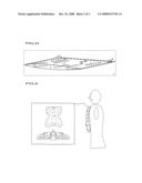
[0015]FIG. A illustrates the different parts of the valve.
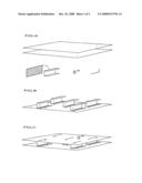
[0016]FIG. B represents a cross section of the first manufacturing step, the thermal bonding of the walls on the lower part of the valve.
[0017]FIG. C represents a cross section of the second manufacturing step, the thermal bonding of the walls on the upper part of the valve.
[0018]FIG. D represents a cross section of the last step, which consists in joining by thermal bonding the valve's upper part to its lower part, on their edge.
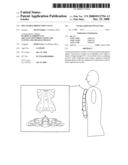
[0019]FIG. E represents the valve placed by way of example of a location on a human body.
[0020]By reference to these drawings, the invention comprises flexible high-strength PVC sheets 1 onto which walls of flexible high-resistance PVC 2 and an inflating end 3 are fitted by thermal bonding to achieve a valve 5.
[0021]The sizes of the walls 2 are adapted according to the size and air volume of the valve. Their spacing is different according to the expected effect. The closer together they are, the more the impact will be absorbed.
[0022]By way of example, the valve illustrated in FIG. E will have dimensions of approximately 30 cm by 40 cm. And the walls in FIG. A will have dimensions of 10 cm by 3 cm, at a distance of 1 cm.
[0023]FIG. A illustrates the elements constituting the inflatable protection valve according to an embodiment of the invention. These are two PVC sheets 1, two PVC walls 2, one of the walls 2 being folded on two of its extremities, an inflating end 3 and a dotted line representing a thermal bonding 4.
[0024]FIG. B shows one of the two PVC sheets 1 onto which PVC walls 2 have been fitted by thermal bonding on one of their extremities.
[0025]FIG. C shows the second PVC sheet 1 placed opposite the first PVC sheet 1 and assembled to the elements of FIG. B by thermal bonding 4 on the other extremity of each of the walls 2. The second PVC sheet 1 comprises the inflating end 3.
[0026]FIG. D illustrates the last manufacturing step of the inflatable valve 5, where the two PVC sheets 1 are thermally bonded to one another on their periphery to close off the air chamber of the inflatable valve 5 of the invention.
[0027]FIG. E shows an inflatable valve 5 according to the invention adapted to the protection of the torso of a human being. The inflatable valve 5 has an ergonomic shape adapted to its function. The walls inside the inflatable valve 5 are arrayed according to a specific layout to achieve the sought protective effect. The walls are arranged along different axes forming acute angles between at least some of them. The space between the walls is sufficient to allow air to circulate around each wall. The walls do not form compartments.
[0028]According to what is visible in FIGS. A to E and to what has been described here above, the inflatable protection valve 5 of the invention comprises a single air chamber and an adapter 3 for inflating the air chamber. The valve 5 has a lower part constituted of a flexible high-strength PVC sheet 1 and an upper part constituted of a flexible high-strength PVC sheet 1. The upper part and the lower part are joined to one another on their edge by thermal bonding. The valve 5 further comprises a plurality of walls 2 of flexible high-strength PVC placed inside the air chamber and fitted by thermal bonding on the one hand to the upper part and on the other hand to the lower part. The walls 2 are at a distance from one another to allow air to circulate between them when the valve 5 is inflated.
[0029]According to a preferred embodiment, the protective inflatable valve comprises high-strength PVC sheets 1 and an inflating end 3. The sheets 1 are joined to one another by thermal bonding 4 to form an enclosure of small thickness capable, after inflation, of protecting efficiently body parts from shocks and impacts.
[0030]Walls 2 are fitted between the high-strength PVC sheets 1 by thermal bonding 4. The walls are configured as a labyrinth in order to better regulate the air flow in case of shock or impact.
[0031]By modifying the size of the valve 5 and the size of the walls 2, it is possible to achieve different levels of protection on different parts of the body.
[0032]The valve can be used, by way of non-limiting example, in action sports.
User Contributions:
comments("1"); ?> comment_form("1"); ?>Inventors list |
Agents list |
Assignees list |
List by place |
Classification tree browser |
Top 100 Inventors |
Top 100 Agents |
Top 100 Assignees |
Usenet FAQ Index |
Documents |
Other FAQs |
User Contributions:
Comment about this patent or add new information about this topic:
| People who visited this patent also read: | |
| Patent application number | Title |
|---|---|
| 20140281636 | MOBILE SYSTEMS WITH SEAMLESS TRANSITION BY ACTIVATING SECOND SUBSYSTEM TO CONTINUE OPERATION OF APPLICATION EXECUTED BY FIRST SUBSYSTEM AS IT ENTERS SLEEP MODE |
| 20140281635 | REDUCING POWER CONSUMPTION DURING IDLE STATE |
| 20140281634 | CONTROLLING POWER SUPPLY UNIT POWER CONSUMPTION DURING IDLE STATE |
| 20140281633 | Magnet Key |
| 20140281632 | ELECTRONIC APPARATUS THAT MEASURES POWER DURING POWER SAVING STATE, METHOD OF CONTROLLING THE SAME, AND STORAGE MEDIUM |
Images included with this patent application:
 |  |
 |
| Similar patent applications: | |
| Date | Title |
|---|---|
| 2013-08-29 | Offensive and defensive protection device |
| 2012-10-04 | Finger protector kitchen gloves |
| 2013-08-22 | Personal impact protection device |
| 2013-08-29 | Garment protection device and method of use |
| 2013-09-05 | Shirt with an elastic lower portion and a lower protruding band |
| New patent applications in this class: | |
| Date | Title |
|---|---|
| 2019-05-16 | Impact absorbing structures in body protective equipment |
| 2016-12-29 | Inflatable safety garment |
| 2016-03-10 | Body protector |
| 2016-01-14 | Impact sensing ballistic vest and method for communicating data thereof |
| 2015-05-21 | Protective gear |
| Top Inventors for class "Apparel" | |
| Rank | Inventor's name |
|---|---|
| 1 | William L. Grilliot |
| 2 | Mary I. Grilliot |
| 3 | David Turner |
| 4 | Patricia K. Waters |
| 5 | Caleb Clark Crye |