Patent application title: Storage Box
Inventors:
Brian Timothy Boland (Thirroul, AU)
IPC8 Class: AB65D542FI
USPC Class:
493102
Class name: Rigid container (e.g., box, carton, cap, cup, etc.) assembling of distinct members including application of distinct closure
Publication date: 2008-12-18
Patent application number: 20080312054
Inventors list |
Agents list |
Assignees list |
List by place |
Classification tree browser |
Top 100 Inventors |
Top 100 Agents |
Top 100 Assignees |
Usenet FAQ Index |
Documents |
Other FAQs |
Patent application title: Storage Box
Inventors:
Brian Timothy Boland
Agents:
KNOBBE MARTENS OLSON & BEAR LLP
Assignees:
Origin: IRVINE, CA US
IPC8 Class: AB65D542FI
USPC Class:
493102
Abstract:
A stackable and collapsible storage box (100) comprising a foldable
wrapper (10) having side wall and end wall panels which are releasably
retained within a peripheral channel (30a) on a separate base portion
(30). The wall panels have lower extension portions (11, 12) that are
folded upwardly to provide a double thickness and these lower extension
portions have an upper edge (12a) or apertures (37) that engage with
short protrusions (33) formed on an inner wall (32) of the channel to
retain the panels. The end wall panels have upper first and second
extensions portions (14a, 16) that are respectively folded inwardly and
upwardly to provide a support edge (16a) to support hangers for hang
files. The support edge can be strengthened with a channel section (19).
The box can have a lid (50) has a ridge (53) to compliment channel (36)
on the base portion to allow stacking.Claims:
1. A storage box primarily for home or office use comprising at least one
wall panel; said storage box further comprising a separate base portion
provided with an upwardly folded, resiliently biased lower extension
portion, whereby said at least one wall panel is releasably engaged with
said base portion by forcing said upwardly folded extension portion
between said opposing walls of said upper peripheral channel and past
inward facing protrusions disposed along one wall of said opposing walls;
said upwardly folded lower extension portion resiliently biased so as to
spring open sufficient for said extension portion to engage with said
inward facing protrusions.
2. The storage box of claim 1 wherein said at least one wall panel comprises opposing side wall panels and opposing end wall panels.
3. The storage box of claim 2 wherein said opposing side wall panels and said opposing end wall panels are provided as a wrapper; said panels divided by preformed fold lines.
4. The storage box of claim 1 wherein said storage box is provided as a flat pack prior to use.
5. The storage box of claim 1 wherein said at least one wall panel comprises die-cut substantially rigid material; said material provided with pre-formed folds.
6. The storage box of claim 1 wherein said base portion comprises an integrally moulded, substantially planar portion bounded by said upper peripheral channel and a lower peripheral channel.
7. The storage box of claim 6 wherein said opposing walls of said upper peripheral channel comprise an upwardly projecting outer vertical wall and an upwardly projecting inner vertical wall.
8. The storage box of claim 3 wherein said upwardly folded extension portion at each lower edge of said opposing side wall panels and said opposing end wall panels provides a lower double thickness portion along each said lower edge for insertion between said opposing walls of said upper peripheral channel.
9. The storage box of claim 1 wherein each said upwardly folded extension portion is provided with a series of pre-punched holes.
10. (canceled)
11. (canceled)
12. The storage box of claim 9 wherein, when each said upwardly folded extension portion is inserted into said peripheral channel of said base portion, said pre-punched holes engage with corresponding said protrusions.
13. The storage box of claim 3 wherein each of said side wall panels and said end wall panels is provided with an upper extension portion; each said upper extension portion adapted to be folded downwardly about respective upper edges of said side wall panels and said end wall panels to form an upper double thickness portion along each of said panels.
14. The storage box of claim 13 wherein each said upper extension portion of said end wall panels comprises a first extension portion and a second extension portion; said first extension portion folded downwardly from said upper edge and said second extension portion folded upwardly to form a folded lower edge; said second extension portion thereby providing a supporting edge adjacent said upper edge of said end wall panels; said supporting edge positioned below said upper edge of said end wall panels.
15. The storage box of claim 14 wherein said second extension portion is provide with tabs disposed at outer ends of said portion; said tabs adapted to engage with holes in adjoining extension portions of each of said side wall panels; said tabs and said holes arranged so as to maintain said supporting edge in a predetermined position.
16. The storage box of claim 14 or 15 wherein said supporting edge is provided with a length of channel section adapted to fit over said supporting edge; said channel section acting to strengthen and protect said supporting edge from damage.
17. The storage box of claim 15 wherein said predetermined position of each said supporting edge and said channel section at each said end wall panel is adapted to support hangers for hang files.
18. The storage box of claim 14 wherein each of said end wall panels is provided with an aperture adapted for grasping by the hand of a user; an upper edge of said aperture coincident with said folded lower edge.
19. The storage box of claim 3 wherein at least one of said end wall panels is provided with a label holder adapted for retention of an identifying label; said holder provided with projecting lugs adapted for insertion into, and retention in, pre-punched holes provided in one of said end wall panels.
20. The storage box of claim 19 wherein said label holder comprises side members, an upper cross member and a lower cross member; said upper cross member provided with a cut-out portion forming a slot when said holder is assembled to said storage box.
21. The storage box of claim 20 wherein said slot is adapted for insertion therethrough of a half folded standard sized sheet of paper.
22. The storage box of claim 20 wherein said upper cross member is provided with an inwardly projecting lip; said lip adapted to engage an edge of said sheet of paper.
23. The storage box of claim 1 wherein said storage box is provided with a lid portion; said lid portion comprising a substantially planar portion and a peripheral channel portion; said channel portion adapted for engagement with said at least one wall panel.
24. The storage box of claim 1 wherein said base portion is provided with a lower peripheral channel projecting downwardly from said planar portion; said lower peripheral channel adapted to engage with a peripheral upwardly projecting ridge of said lid portion.
25. (canceled)
26. The storage box of claim wherein said lower peripheral channel of said base portion and said upwardly projecting peripheral ridge of said lid portion are adapted for engagement one with the other thereby locating a superior said storage box to a supporting said storage box in a stack of storage boxes.
27. The storage box of claim 24 wherein said lid portion is provided with an opening section; said opening section comprising said substantially planar portion hingedly attached to one side element of said peripheral channel portion.
28. The storage box of claim 3 wherein said side wall panels of said wrapper are provided with central vertical pre-formed folds; said folds adapted to folding said side wall panels for packing into a package; said wrapper when in a folded state for packaging nested within an inverted said lid portion; said lid portion engaged with an inverted said base portion; said base portion enclosing said wrapper to form said package.
29. The storage box of claim 23 wherein said storage box is provided in a package having said base portion and said lid portion forming outer confines of said package; said package including:(a) said wrapper,(b) said base portion,(c) said lid portion,(d) a pair of said channel sections, and(e) a label holder.
30. A method of erecting the storage box of claim 1, said method including the steps of:(a) removing components of said storage box from said package,(b) fitting said at least one side wall panel to said base portion
31. The method of claim 30; said method including the further steps of:(a) arranging said wrapper into a box like configuration,(b) folding said lower extension portions of said side walls and said end walls upwardly at said pre-formed folds,(c) folding said upper extension portions of said side walls and said end walls downwardly,(d) inserting said lower edges of said side walls and said end walls into said peripheral channel of said base portion,(e) folding said second extension portions of said end walls upwardly to provide said supporting edges,(f) fitting said supporting edges with said lengths of channel sections,(g) fitting said lid portion to said upper edges.
32. (canceled)
33. A storage box comprising a one piece wall structure having four articulated walls which may be folded flat and opened out to form a rectangular prism section, said articulated walls having retaining elements at the lower ends of each wall that may be inserted in a channel section at the periphery of an otherwise planar base panel to effect permanent interlocking of walls and base to form an open top box structure; wherein the interlocking of walls and base is effected by means of a short inwardly and upwardly facing return fold at the bottom of each wall panel that co acts with a channel section in the periphery of the base panel such that insertion of the short fold into the base channel causes the upper edge of the fold to become entrapped beneath the edge of a plurality of short inward projecting protrusions within the channel.
34. (canceled)
35. The storage box of claim 33 wherein the interlocking of walls and base is effected by means of an inwardly facing fold having a plurality of holes therein that co acts with a channel section in the periphery of a base panel such that insertion of the fold into the base channel causes the lower edge of the holes to become entrapped beneath the edges of a plurality of short inward projecting protrusions within the channel.
36. The box of claim 33 wherein opposite walls of the wall structure have articulated at their top edge a secondary panel that may be folded down within the box; said secondary panels have toward their midsection a transverse crease such that the lower portion of the fold may be folded back up upon the upper portion so that the edge of the secondary panel terminates at little short of the top edge of the wall and are so positioned to form two support walls for the placement of the notched ends of hanging files; the side edges of the support walls have a short tab that engage reciprocal slots in fold down flaps of adjacent side panels to retain the walls in location; the upper edges of the wall are fitted with channel section lengths to give additional beam strength and to protect the edge from damage by the notched ends of the hanging files.
37. The box of claim 33 having a lid with a downward facing channel section at it's underside periphery such that the channel section releasably engages over the upper edges of the wall structure thereby to enhance structural integrity of said box to increase the load bearing capacity of the walls when boxes are stacked vertically and maintain walls substantially planar.
38. The box of claim 33 having vertical stacking alignment features in the form of a short upstanding wall at the outer periphery of the lid and a reciprocal shallow channel at the lower periphery of the base to loosely accept said short upstanding wall.
39. The box of claim 33 having a lid hingedly fixed with a three sided frame element; said frame element having a channel section with lugs within said channel so that said frame element may be pressed over and grip top edges of a side wall and opposing end walls of said box; said hingedly fixed lid being planar and provided at the edge opposite the hinge with a channel section without said lugs so as to complete the channel section containment of the top edges of said box walls when said lid is in a closed position.
40. The box of claim 33 wherein the wall structure is made of fibre board or any material that supports creased fold lines.
41. The box of claim 33 having any number of side walls and having the base and lid so shaped to accommodate the side walls.
42. (canceled)
43. The storage box of claim 19 wherein said lugs have a configuration relative said frame after insertion into said apertures conforming substantially to configuration of said lugs before said insertion.
Description:
[0001]The Present Invention Relates to Stackable Boxes suitable for use as
general storage boxes and/or as archive boxes for documents and hanging
files, and which are manufactured in a flat pack form to be easily
assembled by the consumer.
BACKGROUND
[0002]Market Researchers know that the average American consumer currently has some twenty thousand individual possessions in their homes and say that this number is growing yearly. A good percentage of these possessions are not often used and are stored indefinitely.
[0003]Companies generally wish to maintain archived copies of past transactions. It is also a requirement in many jurisdictions that matters relating to a company's transactions be retained for a number of years, causing a large accumulation of files and papers, which must then be retrievably archived.
[0004]Additionally, an increasing number of people maintain an office at their home or are establishing small businesses. Consequently there is an expanding need for relatively inexpensive general storage and files storage boxes that are sturdy and stack easily to conserve floor space in storage areas of the home and office.
[0005]Low cost storage and or hanging file boxes that are flat packed and assembled by the consumer are commercially available. These available forms are die cut from sheet fibreboard with fold creases allowing them to be folded into a box structure having four side walls, a bottom formed by interlocking flaps projecting at right angles from the bottom of the side walls, and have an open top. The two opposite edges of the top may be so spaced as to act as rails for the support of standard hanging files. Generally a separate folded fibreboard lid is also provided with these common forms.
[0006]In a variant of this form, disclosed by U.S. Pat. No. 5,494,161, edges for support of hanging files within the box may be formed by a pair of opposite fibreboard flaps that extend vertically from the bottom of the box to a distance short of the top edge of the box.
[0007]A disadvantage of these types of storage boxes, is that their bottoms tend to fail and open when loaded. Also they do not stack well because they do not positively locate one on top of the other, and lack structural integrity to properly support the weight of superior boxes in a stack.
[0008]Additionally, any dampness on the floor of the storage area may result in damage to the contents and softening of the lower portion of the side walls of the bottom box leading to possible failure of the walls and collapse of the stack. Some manufacturers attempt to overcome the structural deficiencies of current forms by using heavier weight fibreboard and the inclusion of more flaps and or additional separate pieces of fibreboard to reinforce the sides and the bottom. However, such structural remedies are a poor use of a natural resource [wood fibre] and significantly increase the cost to the consumer for little net product improvement.
[0009]It is an object of the present invention to address or ameliorate some of the above disadvantages.
[0010]The term "comprising" (and grammatical variations thereof) is used in this specification in the inclusive sense of "having" or "including", and not in the exclusive sense of "consisting only of".
BRIEF DESCRIPTION OF THE INVENTION
[0011]Accordingly, in one broad form of the invention there is provided a storage box primarily for home or office use comprising at least one side wall panel; said storage box further comprising a separate base portion; said at least one side wall panel provided with attachment elements adapted for releasable retention of lower portions of said panels within said base portion.
[0012]Preferably said at least one side wall panel comprises opposing side wall panels and opposing end wall panels.
[0013]Preferably said opposing side wall panels and said opposing end wall panels are provided as a wrapper, said panels divided by preformed fold lines.
[0014]Preferably said storage box is provided as a flat pack prior to use.
[0015]Preferably said wrapper comprises die-cut substantially rigid material; said material provided with pre-formed folds.
[0016]Preferably said base portion comprises a substantially planar portion bounded by an upper peripheral channel.
[0017]Preferably said upper peripheral channel projects upwardly from said substantially planar portion; said channel comprising an outer vertical wall and an inner vertical wall, and wherein at least one of said outer wall and said inner wall is provided with protrusions adapted to releasably engage with said attachment elements of said side wall panels and said end wall panels.
[0018]Preferably said attachment elements comprise lower extension portions at each lower edge of said opposing side wall panels and said opposing end wall panels; said lower extension portions adapted to be folded upwardly so as to provide a lower double thickness portion along each said lower edge.
[0019]Preferably said attachment elements comprise a series of pre-punched holes in said lower extension portions of respective said side wall panels and said end wall panels.
[0020]Preferably said upper peripheral channel of said base portion is adapted to accept insertion of each said lower double thickness portions.
[0021]Preferably when each said double thickness portion is inserted into said peripheral channel of said base portion, an upper edge of each said lower extension portion is releasably retained by said protrusions.
[0022]Preferably when each said lower extension portion is inserted into said peripheral channel of said base portion, said pre-punched holes engage with corresponding said protrusions.
[0023]Preferably each of said side wall panels and said end wall panels are provided with an upper extension portion; each said upper extension portion adapted to be folded downwardly about respective upper edges of said side wall panels and said end wall panels to form an upper double thickness portion along each of said panels.
[0024]Preferably each said upper extension portion of said end wall panels comprises a first extension portion and a second extension portion; said first extension portion folded downwardly from said upper edge and said second extension portion folded upwardly to form a folded lower edge; said second extension portion thereby providing a supporting edge adjacent said upper edge of said end Wall panels, said supporting edge positioned below said upper edge of said end wall panels.
[0025]Preferably said second extension portion is provide with tabs disposed at outer ends of said portion; said tabs adapted to engage with holes in adjoining extension portions of each of said side wall panels; said tabs and said holes arranged se as to maintain said supporting edge in a predetermined position.
[0026]Preferably said supporting edge is provided with a length of channel section adapted to fit over said is supporting edge; said channel section acting to strengthen and protect said supporting edge from damage.
[0027]Preferably said predetermined position of each said supporting edge and said channel section at each said end wall panel is adapted to support hangers for hang files.
[0028]Preferably each of said end wall panel is provided with an aperture adapted for grasping by the hand of a user; an upper edge of said aperture coincident with said folded lower edge.
[0029]Preferably at least one of said end wall panels is provided with a label holder adapted for retention of an identifying label, said holder provided with projecting lugs adapted for insertion into, and retention in, pre-punched holes provided in said end wall panel.
[0030]Preferably said label holder comprises side members, an upper cross member and a lower cross member; said upper cross member provided with a cut-out portion forming a slot when said holder is assembled to said storage box.
[0031]Preferably said slot is adapted for insertion therethrough of a half folded standard sized sheet of paper.
[0032]Preferably said upper cross member is provided with an inwardly projecting lip; said lip adapted to engage an edge of said sheet of paper.
[0033]Preferably said storage box is provided with a lid portion; said lid portion comprising a substantially planar portion and a peripheral channel portion; said channel portion adapted for engagement with said upper edges of said side wall panels and said end wall panels.
[0034]Preferably said base portion is provided with a peripheral lower channel projecting downwardly from said planar portion.
[0035]Preferably said lid portion is provided with an upwardly projection peripheral ridge.
[0036]Preferably said peripheral lower channel of said base portion and said upwardly projecting peripheral ridge of said lid portion are adapted for engagement one with the other thereby locating a superior said storage box to a supporting said storage box in a stack of storage boxes.
[0037]Preferably said lid portion is provided with an opening section; said opening section comprising said substantially planar portion hingedly attached to one side element of said peripheral channel portion.
[0038]Preferably said side wall panels of said wrapper are provided with central vertical pre-formed folds; said folds adapted to folding said side wall panels for packaging; said wrapper when in a folded state for packaging nested within an inverted said lid portion; said lid portion engaged with an inverted said base portion.
[0039]Preferably said storage box is provided in a package; said package including:
[0040](a) said wrapper,
[0041](b) said base portion,
[0042](c) said lid portion,
[0043](d) a pair of said channel sections, and
[0044](e) a label holder.
[0045]In a further broad form of the invention there is provided a method of erecting the storage box, said method including the steps of: [0046](a) removing components of said storage box from said package, [0047](b) fitting said at least one side wall panel to said base portion
[0048]Preferably said method including the further steps of: [0049](a) arranging said wrapper into a box like configuration, [0050](b) folding said lower extension portions of said side walls and said end walls upwardly at said pre-formed folds, [0051](c) folding said upper extension portions of said side walls and said end walls downwardly, [0052](d) inserting said lower edges of said side walls and said end walls into said peripheral channel of said base portion, [0053](e) folding said second extension portions of said end walls upwardly to provide said supporting edges, [0054](f) fitting said supporting edges with said lengths of channel sections, [0055](g) fitting said lid portion to said upper edges.
[0056]In yet a further broad form of the invention there is provided a storage box as herein described and with reference to the accompanying drawings.
[0057]In yet a further broad form of the invention there is provided a storage receptacle comprising a one piece wall structure having four articulated walls which may be folded flat and opened out to form a rectangular prism section said articulated walls having retaining elements at the lower ends of each wall that may be inserted in a channel section at the periphery of an otherwise planar base panel to effect permanent interlocking of walls and base to form an open top box structure.
[0058]Preferably the interlocking of walls and base is effected by means of a short inwardly and upwardly facing return fold at the bottom of each wall panel that co acts with a channel section in the periphery of the base panel such that insertion of the short fold into the base channel causes the upper edge of the fold to become entrapped beneath the edge of a plurality of short inward projecting protrusions within the channel.
[0059]Preferably the interlocking of walls and base is effected by means of an inwardly facing fold having a plurality of holes therein that co acts with a channel section in the periphery of a base panel such that insertion of the fold into the base channel causes the lower edge of the holes to become entrapped beneath the edges of a plurality of short inward projecting protrusions within the channel.
[0060]Preferably opposite walls of the wall structure have articulated at their top edge a secondary panel that may be folded down within the box; said secondary panels have toward their midsection a transverse crease such that the lower portion of the fold may be folded back up upon the upper portion so that the edge of the secondary panel terminates at little short of the top edge of the wall and are so positioned to form two support walls for the placement of the notched ends of hanging files; the side edges of the support walls have a short tab that engage reciprocal slots in fold down flaps of adjacent side panels to retain the walls in location; the upper edges of the wall are fitted with channel section lengths to give additional beam strength and to protect the edge from damage by the notched ends of the hanging files.
[0061]Preferably said receptacle having a lid with a downward facing channel section at it's underside periphery such that the channel section releasably engages over the upper edges of the wall structure thereby to enhance structural integrity of said receptacle to increase the load bearing capacity of the walls when receptacles are stacked vertically and maintain walls substantially planar.
[0062]Preferably said receptacle having vertical stacking alignment features in the form of a short upstanding wall at the outer periphery of the lid and a reciprocal shallow channel to loosely accept said short upstanding wall.
[0063]Preferably said receptacle having a lid with a three sided frame element that fixedly attaches to three adjacent top edges of the wall structure; the middle frame element having a planar panel integrally hinged so as to form a pivotal lid.
[0064]Preferably the wall structure is made of fibre board or any material that supports creased fold lines.
[0065]Preferably any number of side walls and having the base and lid so shaped to accommodate the side walls.
[0066]Preferably said receptacle herein disclosed with reference to any one of the accompanying drawings.
BRIEF DESCRIPTION OF DRAWINGS
[0067]Embodiments of the present invention will now be described with reference to the accompanying drawings wherein:
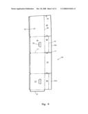
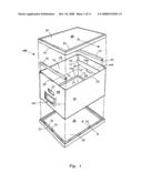
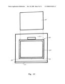
[0068]FIG. 1 is an exploded perspective view of a preferred embodiment of a storage box according to the present invention,
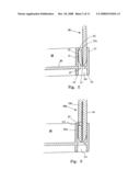
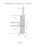
[0069]FIG. 2 is a partial Section View showing a preferred means of engaging the side wall panels of the storage box of FIG. 1 to a base portion,
[0070]FIG. 3 is a partial section view showing a preferred means of engaging the side wall panels with the base of FIGS. 1 and 2 by use of a plurality of holes in the lower ends of the side wall panels,
[0071]FIG. 4 shows a partial section view of a preferred alignment means for stacking the storage boxes of FIG. 1 one on top of another,
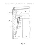
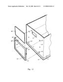
[0072]FIG. 5 shows a partial section view of one end of a preferred embodiment of a storage box wherein hanging files may be supported and contained within the box,
[0073]FIG. 6 is a die-cut blank preferred embodiment of the side wall panels,
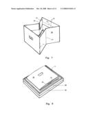
[0074]FIG. 7 shows a perspective view of a preferred form of the articulated side wall panels provided with additional centre folds so as to allow the panels to fold into a shorter length,
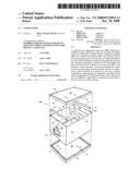
[0075]FIG. 8 shows a perspective view of the side wall panels of FIG. 7 folded down flat within the periphery of a lid, with the lid nested with the base,
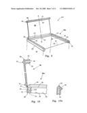
[0076]FIG. 9 shows a perspective view of another preferred embodiment of a lid for the storage box of FIGS. 1 to 8 wherein a planar portion of the lid is hingedly attached to a part of a lid frame,
[0077]FIG. 10 and 10A show partial section views of the lid of FIG. 9 along the lines A-A and B-B respectively,
[0078]FIG. 11 is a partial perspective view of one end of the storage box of FIG. 1 showing a preferred form of a label holder and label,
[0079]FIG. 12 is an end elevation view of the end of the storage box of FIG. 11 with a label holder attached to the box and a label inserted in the holder,
[0080]FIGS. 13 and 14 are sectioned views of the label holder of FIGS. 11 and 12;
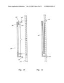
[0081]FIG. 15 is a perspective view of a storage box of substantially circular wall configuration according to a further preferred embodiment and
[0082]FIG. 16 is a perspective view of a storage box of substantially triangular wall configuration according to yet a further preferred embodiment.
DETAILED DESCRIPTION OF PREFERRED EMBODIMENTS
First Preferred Embodiment
[0083]FIGS. 1,2,4,5,6,7 and 8 show a first embodiment of a storage box 100 according to the present invention, which includes a substantially rigid wrapper 10 forming four articulated side wall panels. As shown in FIG. 6, the side wall panels are pre-cut as a single die-cut piece of fibreboard or other suitable material, provided with preformed folds 11, 15, 20 and 21. An end tab 23 allows the wrapper 10 to be joined at the outer ends, for example by self adhesive strips to form the rectangular box-like form shown in FIG. 1. The joining of the outer ends of the wrapper may be left to a user when the box is erected for use, or may be joined at the manufacturing stage.
[0084]With reference to FIGS. 1 and 6, the upper edges 20 of the side wall panels of wrapper 10, are provided with extension portions to give a double thickness of material to the upper parts of the side wall panels when folded about fold lines at edges 20. The lower edges 21 of the side wall panels are likewise, in this embodiment of the invention, provided with lower extension portions 12, which when folded upwardly about fold lines at edges 21, provide a portion of double wall thickness along the lower periphery of the wrapper 10 as shown in FIG. 1.
[0085]A base portion 30 is preferably injection moulded from a suitable plastic. Base portion 30 is a planar rectangular panel provided at its periphery with an upwardly projecting upper channel formation 30A comprising two upstanding substantially parallel walls, outer wall 31 and inner wall 32 as best seen in FIGS. 1, 2 and 3. Walls 31 and 32 are spaced apart a little more than the double thickness of material at the lower edge of wrapper 10. Inner wall 32 is provided with inward facing short protrusions 33 spaced around the top inner edge of the inner wall 32. The depth of the upper channel formation 30A beneath each short protrusion 33 is substantially equal with the height of the short extension portions 12 at the lower edges 21 of the wrapper 10.
[0086]The lower portions of the side wall panels and folded over extension portions 12 are forced between opposing outer walls 31 and inner walls 32 of base 30 and past the front faces of the short protrusions 33. When folded edge 21 is seated at the bottom of the channel formation 30A, the resiliently biased folded over portions 12 spring open a little so that the top edges 12a of the short return folds 12 become locked beneath the short inward facing protrusions 33 to lock the wrapper 10 to the base 30.
[0087]Preferably, as shown in FIG. 2, the base portion of the channel formation 30A between outer wall 31 and inner wall 32 is provided with slots 37. These allow the insertion of a suitable implement to force folded over portions 12 back against the inside surfaces of the side wall panels of the wrapper 10. By this means the upper edges 12a may be released from engagement with protrusions 33 allowing an assembled box to be disassembled and returned to a flat pack state for compact storage and later re-use. In addition to providing a means of disassembly of the side wall panels from the base portion, the aperture 37 also permit simplified tooling for injection moulding.
[0088]Opposing upper extension portions 13 of the longer opposing side walls and upper extension portions 16 of the shorter opposing end walls 14, are arranged to interfere at their meeting edges when folded downward so as to maintain their position. The upper extension portion 16 of the two opposing end side walls 14r are provided with a transverse crease 15; to allow the lower portions of flaps 16 to be folded upward, if the storage box 100 is to be used for storing files in file hangers. When these lower portions are in this upward folded position, the upper edges 16a are located sufficiently below the level of top edge 20 of the side walls to allow for the depth of hang file rails as shown in FIG. 5 and hang file labels or tags (not shown) which project above the rail.
[0089]To secure the lower portions of extension portions 16 in the correct position (as shown in FIGS. 1 and 5) to accept the notched ends 71 of hanging files 70, tabs 17 provided at the outer ends of the extension portions engage with corresponding holes 18 in the adjacent side extension portions 13. When tabs 17 of extension portions 16 are assembled to holes 18, the edges 16a at opposing end walls 14 are so separated as to suit the length and depth of standard hanging files 70.
[0090]As best seen in FIG. 5, top edges 16a are preferably capped with a length of plastic channel section 19 to protect the edges 16a and add beam strength so as to better support the notched ends 71 of file hangers 70 and the weight of files.
[0091]For storage purposes other than that of files in hangers, lower portions 16 are folded back into contact with the upper section of flap 14a, and are retained in this un-obstructing position by the engagement of tabs 17 in notches (not shown) in the ends of the side flaps 13.
[0092]The opposing end walls 14 are provided with hand holes 22 to allow lifting of the storage box. Bottom folds 15 of flaps 14a are coincident with the top edges of hand holes 22 such that three material thicknesses are grasped when lifting the box 100.
[0093]The Storage box 100 of this first preferred embodiment of the invention is provided with a lid 50, injection moulded from a suitable plastic. Lid 50 comprises a substantially planar panel provided at its periphery with a downwardly projecting channel 36 comprising an inner wall 51 and outer wall 52. Walls 51 and 52 are so spaced apart that the channel formation may be placed over folded over upper edges 20 of the side wall panels of the wrapper 10, as shown in FIGS. 4 and 5. The lid 50 functions firstly to close the top of the box and secondly to prevent the side walls from bowing in or out, thereby adding significantly to the integrity of the box when supporting the weight of superior boxes in a stack of boxes.
[0094]The base 30 and lid 50 are provided with mating elements, peripheral downwardly projecting lower channel 36 and peripheral upwardly projecting ridge 53 respectively, as best seen in FIG. 4. These mating elements allow one box to be accurately and securely stacked one above another when ridge 53 is located in channel 36.
[0095]In this first preferred form, the components of storage box 100 are provided to the consumer in flat pack form, for assembly by the consumer.
Second Preferred Embodiment
[0096]In a second fore of the invention shown in FIGS. 7 and 8, the wrapper 10 has an additional fold line 24 down the centre of the two opposite longer side walls. Folds 24 allow the wrapper 10 to be folded into a shorter pack and nested within the periphery of the inverted lid 50. As can be seen in FIG. 8, inverted lid 50 may in turn be nested within the inverted base 30 to provide a compact flat assembly which may be packaged for example by shrink wrapping for point of sale.
[0097]Third Preferred Embodiment
[0098]With reference to FIG. 3, in a further preferred form of the invention, attachment of the wrapper 10 with the plastic base 30 is effected by punched holes 25 provided in extended folded portions 10b engaging with the afore described protrusions 33. Although FIG. 3 shows the punched holes 25 in the upturned portions 10b, holes 25 could alternatively be formed in end wall panel 14, Retaining protrusions 33 would then be located at the inner edges of the outer wall 31 of the base 30.
Fourth Preferred Embodiment
[0099]In yet a further preferred form of the invention, the wrapper 10 may be formed from a creasable and foldable plastic material. The plastic material is provided with punched holes adjacent lower edges 21 to engage with a number of corresponding protrusions at the inner or outer walls 32 and 31 as described above. In this embodiment, the side wall panels of the wrapper 10 need not be provided with folded over portions 12, so that a single thickness of the panel material is retained in a narrower channel formation between the inner and outer walls.
Fifth Preferred Embodiment
[0100]In yet another form of the invention the wrapper 10 may be formed from a plastic material suitable for injection moulded integral hinges, and provided with saw-tooth like protrusions along the lower edges 21 for snap-lock engagement with the channel formations of base moulding 30.
Sixth Preferred Embodiment
[0101]With reference to FIGS. 9, 10 and 10a, the lid 50 comprises a planar portion 56 and peripheral channel formations as described above engaging with the upper edges 20 of three of the side wall panels of wrapper 10, that is along one longer side panel and along the opposing end wall panels 14. At least one of the inner edges of the inner and outer walls forming the peripheral channel formation, is provided with retention lugs 62 projecting into the channel formation. Lugs 62 are preferably tooth-shaped so as to initially allow insertion of the upper folded over edges 20 but subsequently grip the material of the panels.
[0102]In this embodiment planar portion 56 is attached by an integral hinge 57 along the outer upper edge of outer wall 51 of channel formation 61 along the longer side wall. Integral with planar portion 56 is the length of channel formation 64 opposite hinge 57. The length of channel formation 64 is provided with an extending lip 58 as a gripping ledge for opening lid 50.
Seventh Preferred Embodiment
[0103]The storage box of any one of the above described embodiments, may be provided with a label holder 80 as shown in FIGS. 1, 11 and 12 for attachment to one side wall panel, preferably a shorter end side wall panel 14, for insertion therein of a label identifying the contents and other data relative to the storage box. The holder 80 may be of injection moulded plastic and provided, at least at the four corners of the holder, with suitable lugs 82 for insertion into corresponding pre-punched holes in the material of the wrapper 10. The method of assembly is best seen in the sectioned views of FIGS. 13 and 14.
[0104]As also best seen in FIGS. 13 and 14, the upper cross member 83 of holder 80 is formed with a cut-out portion 85 so that when assembled to the surface of end side wall panel 14, cut out portion 85 provides a slot for the insertion of a label therethrough.
[0105]In a particular preferred form of the label holder 80 shown in FIGS. 11 and 12, the holder is sized to accept a to half folded over sheet of a standard sized paper. Thus for example, for storage boxes for use in the United States, the label holder 80 would be sized to suit letter sized paper, while for Europe and other metric countries, the holder would accept a folded sheet of A4. Once inserted, the label is retained by the outer edged of the folded sheet catching under an internal projecting lip 87 provided at upper cross member 83.
In Use
[0106]The components comprising the storage box as herein above described are preferably provided as a flat pack package for erection as required by a user. After removal of the components, the wrapper is arranged to form the four-side box structure and the upper and lower extension portions folded as described. The lower, now folded edges of the wrapper, are then pushed into the channel of the base portion. If the box is to be used for hang files, the end wall extension portions are folded into the correct position and fitted with the lengths of channel sections. Finally the lid is fitted over the upper folded edges of the four side walls.
[0107]It will be appreciated that the combination of the double thicknesses of the upper and lower edges of the four walls when engaged with the respective peripheral channels of the base portion and the lid portion, provide a much stronger box than that of a conventional fibreboard storage box. The peripheral channel of the lid in particular prevents the bowing out or in of the upper edges of the box, thus allowing a box to support a far greater stack of superior boxes.
[0108]Should a once erected box not be required for some length of time, the structure is readily dismantled back to a flat pack configuration for compact storage against future use.
[0109]The above describes only some embodiments of the present invention and modifications, obvious to those skilled in the art, can be made thereto without departing from the scope and spirit of the present invention. Thus for example, the wrapper making up the four side wall portions need not be formed of one piece of material but could be supplied as two or even four separate sections provided with suitable tabs at the outer vertical edges for assembly into the opposing side walls and end walls of the box structure.
[0110]Further modifications envisaged in the present invention include storage boxes of a variety of shapes including circular, triangular (refer FIGS. 15 and 16) and various regular and irregular polygons. Shapes may also include combinations of arcuate and straight sides to suit particular shapes of articles to be stored. Regardless of the number and configuration of the side walls, the method of engagement of the walls with a suitably shaped base portion remains as described for the four sided embodiment above.
User Contributions:
comments("1"); ?> comment_form("1"); ?>Inventors list |
Agents list |
Assignees list |
List by place |
Classification tree browser |
Top 100 Inventors |
Top 100 Agents |
Top 100 Assignees |
Usenet FAQ Index |
Documents |
Other FAQs |
User Contributions:
Comment about this patent or add new information about this topic:
Images included with this patent application:
 |  |
 |  |
 |  |
 |  |
 |  |
 |  |
| New patent applications in this class: | |
| Date | Title |
|---|---|
| 2014-09-04 | Thermoforming packing machine |
| 2011-03-03 | Method and device for making boxes from a set of blanks |
| Top Inventors for class "Manufacturing container or tube from paper; or other manufacturing from a sheet or web" | |
| Rank | Inventor's name |
|---|---|
| 1 | Thomas D. Wetsch |
| 2 | Amer Aganovic |
| 3 | Robert Tegel |
| 4 | Uwe Schneider |
| 5 | Shuuya Nagasako |