Patent application title: COOKING PAN PROTECTION SYSTEM
Inventors:
Carmen Albert (Edwards, CO, US)
IPC8 Class: AB65D8562FI
USPC Class:
206485
Class name: Special receptacle or package article held in apertures of opposed walls
Publication date: 2008-12-11
Patent application number: 20080302693
nd method for protecting a surface of a cooking
pan is disclosed. Such a system includes at least a first pocket, a
second pocket and a pocket divider placed between the first and second
pocket for protecting the surface of a number of cooking pans.Claims:
1. A cooking pan protection system, comprising:a first pocket having a
first interior wall member forming a first interior volume and a first
exterior wall member forming an outer layer, the first interior wall
member being made from a material selected to protect a surface of a
first cooking pan from being scratched, the first pocket further having a
first opening configured to accept the first cooking pan into the first
interior volume of the first pocket;a second pocket having a second
interior wall member forming a second interior volume and a second
exterior wall member forming the outer layer, the second interior wall
member being made from a material selected to protect a surface of a
second cooking pan from being scratched, the second pocket further having
a second opening configured to accept the second cooking pan into the
second interior volume of the second pocket; anda pocket divider coupled
between the first pocket and the second pocket, a first wall of the
pocket divider forming a bottom interior wall of the first interior
volume of the first pocket, a second wall of the pocket divider forming a
top interior wall of the second interior volume of the second pocket, the
pocket divider being made from the same material as the first interior
wall member.
2. The system of claim 1, wherein the material of the first interior wall member will not absorb moisture from the first cooking pan.
3. The system of claim 1, wherein the material of the first interior wall member will absorb moisture from the first cooking pan.
4. The system of claim 1, wherein the first opening comprises:an opening volume formed from material between an inner stitched seam and an outer stitched seam; andan elastic band positioned inside the opening volume.
5. The system of claim 4, wherein the first opening has a resting position diameter when the elastic band is in a resting position.
6. The system of claim 5, wherein the first opening has an expanded position diameter when the elastic band is stretched to a maximum elasticity, the expanded position diameter being greater than the resting position diameter.
7. The system of claim 1, wherein a diameter of the first opening is the same as a diameter of the second opening.
8. The system of claim 1, wherein a diameter of the first opening is less than a diameter of the second opening.
9. The system of claim 6, wherein the resting position diameter of the first opening is less than the resting position diameter of the second opening.
10. The system of claim 6, wherein the expanded position diameter of the first opening is less than the expanded position diameter of the second opening.
11. The system of claim 1, wherein the first opening comprises:an opening volume formed from material between an inner stitched seam and an outer stitched seam, the opening volume having a first string opening and a second string opening;a draw string positioned inside the opening volume, the draw string having a first end protruding out of the first string opening and a second end protruding out the second string opening; anda coupler to fix a position of the first end and the second end of the draw string together.
12. The system of claim 11, wherein a diameter of the first opening is adjustable depending on the position of the coupler along a length of the draw string.
13. A method of protecting a surface of a plurality of cooking pans, comprising:providing a first pocket having a first interior wall member forming a first interior volume and a first exterior wall member forming an outer layer, the first interior wall member being made from a material selected to protect the surface of a first cooking pan from being scratched, the first pocket further having a first opening configured to accept the first cooking pan into the first interior volume of the first pocket;providing a second pocket having a second interior wall member forming a second interior volume and a second exterior wall member forming the outer layer, the second interior wall member being made from a material selected to protect the non-stick surface of a second cooking pan from being scratched, the second pocket further having a second opening configured to accept the second cooking pan into the second interior volume of the second pocket;coupling a pocket divider between the first pocket and the second pocket, a first wall of the pocket divider forming a bottom interior wall of the first interior volume of the first pocket, a second wall of the pocket divider forming a top interior wall of the second interior volume of the second pocket, the pocket divider being made from the same material as the first interior wall member;placing the first cooking pan having a surface into the first opening of the first pocket; andplacing a second cooking pan having a surface into the second opening of the second pocket.
14. The method of claim 13, wherein the material of the first interior wall member will not absorb moisture from the first cooking pan.
15. The method of claim 13, wherein the material of the first interior wall member will absorb moisture from the first cooking pan.
16. The method of claim 13, wherein the first opening is formed by:creating an opening volume formed from material stitched between an inner seam and an outer seam; andpositioning an elastic band inside the opening volume.
17. The method of claim 16, wherein the first opening has a resting position diameter when the elastic band is in a resting position.
18. The method of claim 16, creating an expanded position diameter by stretching the elastic band to its maximum elasticity, the expanded position diameter being greater than the resting position diameter.
19. The method of claim 13, wherein the first opening is formed by:creating an opening volume formed from material stitched between an inner seam and an outer seam;creating a first string opening and a second string opening in the opening volume to allow two ends of a draw string to protrude through the first and second string openings;positioning a draw string inside the opening volume, the draw string having a first end and a second end;positioning the first end of draw string through the first string opening;positioning the second end of the draw string through the second string opening; andpositioning the first and second end of the draw string through an opening in a coupler having means to fix the first and second string ends into a fixed position.
20. The method of claim 19, further comprising:adjusting the diameter of the first opening by sliding the coupler along a length of the draw string.Description:
BACKGROUND OF THE INVENTION
[0001]1. Field of the Invention
[0002]This invention relates to kitchenware and more particularly to the protection of a surface of a kitchen item.
[0003]2. The Relevant Technology
[0004]Many types and brands of cooking or frying pans are coated with a non-stick material such as polytetrafluoroethylene--which is more recognizable by its trademarked name of Teflon®. Teflon® is applied to the surface of a metallic pan to prevent food from sticking to the pan's surface. Non-stick coatings, however, are easily scratched and damaged if the surface comes into contact with hard or sharp objects such as metal spatulas and silverware. Once a non-stick surface has been scratched, its non-stick characteristics are compromised and the pan is no longer effective.
[0005]It is common for manufacturers to sell several pans in a kit of increasing sizes, such that a pan of a smaller size may be stacked on top of and inside the next larger size. Such a configuration is convenient for shipping and for home storage of the pans. However, the stacking of pans may scratch the non-stick coating of the adjacent pan.
[0006]Paper or cloth towels may be placed between each pan to act as a protective barrier so as to prevent each non-stick surface from coming in contact with the bottom of the adjacent pan. Spacers may raise the bottom of one pan from the surface of another. However, spacers can move around and easily go out of alignment or become lost, thereby reducing or completely eliminating the effectiveness as a protective element. Pan liners may also be used to separate the surface from the bottom of an adjacent pan, however, each liner must be sized for each pan's diameter. It is therefore desirable to provide a method and apparatus for separating surfaces of pots and pans while stopping, transporting or otherwise. It is further desirable that such a protective barrier be inexpensive while maintaining its effectiveness.
BRIEF SUMMARY OF THE INVENTION
[0007]The invention is generally directed to a system and method for protecting a surface of a cooking pan. Such a system includes a first pocket having a first interior wall member that forms a first interior volume. The first pocket also has a first exterior wall member forming an outer layer. The first interior wall member is made from a material selected to protect the non-stick surface of a first cooking pan from being scratched. The first pocket also has a first opening that accepts the first cooking pan into the first interior volume of the first pocket.
[0008]The system further has a second pocket having a second interior wall member forming a second interior volume and a second exterior wall member forming the outer layer. The second interior wall member is made from material selected to protect the non-stick surface of a second cooking pan from being scratched. The second pocket further has a second opening that accepts the second cooking pan into the second interior volume of the second pocket.
[0009]Lastly, the system has a pocket divider placed between the first and second pocket. The first wall of the pocket divider forms the bottom interior wall of the first interior volume of the first pocket. A second wall of the pocket divider forms a top interior wall of the second interior volume of the second pocket. The pocket divider is made from the same material as the first interior wall member.
[0010]A method of protecting a non-stick surface of a plurality of cooking pans is provided. The method includes providing a first pocket having a first interior wall member that forms a first interior volume. The first pocket also has a first exterior wall member forming an outer layer. The first interior wall member is made from a material selected to protect the non-stick surface of a first cooking pan from being scratched. The first pocket further has a first opening configured to accept the first cooking pan into the first interior volume of the first pocket.
[0011]The method further provides a second pocket having a second interior wall member that forms a second interior volume and a second exterior wall member forming the outer layer. The second interior wall member is made from a material selected to protect the non-stick surface of a second cooking pan from being scratched. The second pocket further has a second opening configured to accept the second cooking pan into the second interior volume of the second pocket.
[0012]The method further couples a pocket divider between the first pocket and the second pocket. The first wall of the pocket divider forms the bottom interior wall of the first interior volume of the first pocket. The second wall of the pocket divider forms the top interior wall of the second interior volume of the second pocket. The pocket divider is made from the same material as the first interior wall member. The method further requires placing the first cooking pan having a non-stick surface into the first opening of the first pocket. Lastly, the method requires placing the second cooking pan having a non-stick surface into the second opening of the second pocket.
[0013]Other aspects of the present invention will become readily apparent after reading the detailed description in conjunction with the appended claims.
BRIEF DESCRIPTION OF THE DRAWINGS
[0014]To further clarify the above and other advantages and features of the present invention, a more particular description of the invention will be rendered by reference to specific embodiments thereof which are illustrated in the appended drawings. It is appreciated that these drawings depict only typical embodiments of the invention and are therefore not to be considered limiting of its scope. The invention will be described and explained with additional specificity and detail through the use of the accompanying drawings in which:
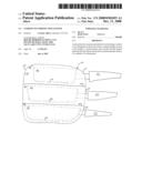
[0015]FIG. 1 is a side view of a plurality of stacked cooking pans;
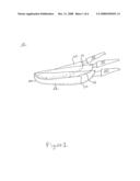
[0016]FIG. 2 is a side view of a plurality of cooking pans placed inside a pan protection system;
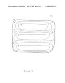
[0017]FIG. 3 is a side view of a pan protection system showing the openings of each pocket of the pan protection system of FIG. 2;
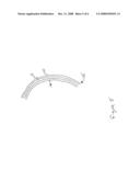
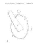
[0018]FIG. 4 is an expanded view of a pocket opening having an expanding and contracting material around the perimeter of the opening;
[0019]FIG. 5 is an expanded view of an elastic opening; and
[0020]FIG. 6 is an expanded view of an opening of a pan protection system with a draw string.
DETAILED DESCRIPTION OF THE PREFERRED EMBODIMENTS
[0021]In the following description, numerous specific details are set forth, such as examples of specific cooking pan sizes, to provide a thorough understanding of the present invention. It will be readily apparent to one of ordinary skill in the art that the present invention may be practiced without the specific details. In other instances, well-known components or methods have not been described in detail but rather in a block diagram in order to avoid unnecessarily obscuring the present invention. Thus, the specific details set forth below are merely exemplary and are by no means intended to be exhaustive. The specific details may be varied from and still be contemplated to be within the spirit and scope of the present invention.
[0022]Reference to "one embodiment" or "an embodiment" means that a particular feature, structure, or characteristic described in connection with the embodiment is included in at least one embodiment of the invention. The appearances of the phrase "in one embodiment" in various places in the specification are not necessarily all referring to the same embodiment.
[0023]FIG. 1 illustrates a side view of a plurality of stacked cooking pans. Stacking pans or other kitchenware is typical of both the home or commercial environment. Since multiple size pans are desirable, pans 20, 30, 40 are illustrated as sized with differing diameters. In the illustrated embodiment, pan 20 is 12 inches in diameter, pan 30 is 10 inches in diameter and pan 40 is 8 inches in diameter. Thus, pan 40 fits inside pan 30, with the combination of pans 40 and 30 fitting inside pan 20. Pans 20, 30, 40 have handles 25, 35, 45 respectively. In the embodiment shown, pans 20, 30, 40 have non-stick coatings 22, 32, 42 on the inner surface of each pan. The illustrated embodiment is shown and described with non-stick coatings, however, the invention works equally as well with pans having any type of a surface that is susceptible to scratches and wear and tear. In the storage configuration illustrated in FIG. 1, non-stick coatings 22, 32, 42 are susceptible to scratching when they are placed directly against the bottom of the adjacent pan. Since pan 30 is placed on top of pan 20 in a typical storage configuration, non-stick coating 22 is placed in direct contact with the bottom surface of pan 30. Any movement of pan 30 results in possible damage to surface 22.
[0024]FIG. 2 illustrates a side view of a plurality of cooking pans placed inside pan protection system 100. Pan protection system 100 is a multi-tiered enclosure that accepts a single pan into a pocket of each tier. In this example, pan protection system 100 comprises three tiers, where each tier has a pocket for receiving a pan. In the illustrated embodiment, pocket 101 is in the top tier, pocket 102 is in the middle tier and pocket 103 is in the bottom tier. Pockets 101 and 102 are divided by pocket divider 110 and pockets 102 and 103 are divided by pocket divider 120.
[0025]Pan protection system 100 and each of its pockets 101, 102 and 103 comprise an outer layer 140 and an inner layer 150. Outer layer 140 is typically made of a cloth-type material that provides flexibility, surface protection and washability. The choice of material is not significant to the operation of the system as long as it protects the surface of the pans and may be washed. Inner layer 150 is permanently coupled to outer layer 140 using an adhesive means. For example, inner layer 150 may be adhered to outer layer 140 using a connection means such as glue, stitching and zippers to mention a few. Inner layer 150 shall be manufactured of a material that protects the surface of cooking pans from damage from other pans that may come in physical contact with the surface. Layer 150 is in direct contact with the non-stick coatings, hence, layer 150 typically is manufactured of a material that will not cause damage to the non-stick coating. In another embodiment, inner layer 150 and outer layer 140 are manufactured from a single piece of material.
[0026]Each pocket has an opening that allows a pan to be inserted. In the illustrated embodiment, pocket 101 has opening 115 for accepting pan 40 and protecting its coating 42; pocket 102 has opening 125 for accepting pan 30 and protecting its coating 32; and pocket 103 has opening 135 for accepting pan 20 and protecting its coating 22.
[0027]In particular embodiments, each pocket and its corresponding opening has ascending or descending sizes based upon the diameter of the pan being inserted into the pocket. For example, pocket 101 and its opening 115 may be sized to accept 8 inch frying pan 40, while pocket 102 and its opening 125 may be sized to accept 10 inch frying pan 30 and pocket 103 and its opening 135 may be sized to accept 12 inch frying pan 20. In another particular embodiment, each pocket and its corresponding opening is the same size, thereby allowing various sized pans with varying diameters to be placed in any of the pockets.
[0028]In the example illustrated in FIG. 2, pan protection system 100 comprises three tiers. In operation, typical household pot and pan kits often have three pans having an 8, 10 and 12 inch diameter respectively. It should be understood that a pan protection system 100 may have more or less than three tiers without departing from the intended scope of the present invention. For example, a pan protection system 100 may have a fourth tier sized with a pocket large enough to accept a pan with a 14 inch diameter. Typically, the largest sized tier is the bottom tier, thereby allowing the descending sized pans to fit within the bottom tier's pocket and its larger diameter pan. The four-tier pan protection system may also have equally sized pockets, thus allowing any sized pan to fit inside any one of the four pockets.
[0029]FIG. 3 illustrates another side view of pan protection system 100 showing the openings of each pocket. Pan protection system 100 has pockets 101, 102 and 103. Pocket 101 and 102 are divided by pocket divider 110 and pocket 102 and 103 are divided by pocket divider 120. Pockets 101, 102 and 103 have openings 115, 125 and 135, respectively. Pan protection system 100 is also comprised of outer layer 140 and inner layer 150, with each layer being adhered to each other as described above. In one embodiment, each opening is approximately sized to the size and dimensions of its corresponding pocket. For example, the size and dimensions of opening 135 are similar to that of pocket 103 so that opening 135 accepts pan 20.
[0030]In another embodiment, the circumference of each opening is manufactured of an expanding and contracting material, which allows the opening to close around a pan once it is inserted. Such an arrangement allows the handle to protrude out of the opening. In an expand position, the opening is still wide enough to accept a large diameter pan.
[0031]FIG. 4 illustrates an expanded view of an opening in one of the pockets with an expanding and contracting material around the perimeter of the opening. In the illustrated embodiment, pocket 103 has an opening 135. Opening 135 is typically manufactured from an elastic material allowing the opening to expand and contract much like an elastic waste band found on pants. Opening 135 is shown in a contracted position such that the elastic is contracted as tight as possible around handle 25. Pan 20 rests inside pocket 103 with handle 25 protruding through opening 135. Dotted line 139 shows the maximum expansion of opening 135. Expanded opening 139 is configured to expand to at least the diameter of pan 20 to allow the pan to fit past opening 139 and into pocket 103. For example, in a closed or compressed position, opening 135 may have a diameter of four inches. In a fully expanded position, however, opening 135 may have a diameter of 14 inches. Hence, opening 135 would be wide enough to accept at least the diameter of 12 inch pan 20.
[0032]FIG. 5 illustrates an expanded view of elastic opening 135. In one embodiment, opening 135 is made from an elastic band 138 that encircles the entire circumference of, or at least part of, opening 135. Elastic band 138 may be encased by material to protect the band from physical damage and visibility to a user. Inner stitch 136 and outer stitch 137 are formed on each side of band 138 so as to contain band 138 within the material. In one embodiment, the material used to surround elastic band 138 may be the same material used to make the entire pan protection system. The material used to surround elastic band 138 may also be of a different material and configured to accommodate the contraction and expansion of opening 135. As described above with respect to FIG. 4, opening 135 has a diameter of 4 inches when contracted and 14 inches when fully expanded, in one embodiment. Therefore, elastic band 138 may have a circumference such that its compressed or relaxed diameter is 4 inches. An elasticity and thickness is selected that allows elastic band 138 to expand to a diameter of at least 14 inches without breaking or losing elasticity over several hundred stretch and relax operations, in one embodiment. Other embodiments are well suited to other dimensions capable of receiving and contracting around corresponding pans.
[0033]Opening of pan protection system 100 may also use a draw string to increase or decrease the size of the opening. FIG. 6 illustrates an expanded view of a pocket having a draw string to alter the diameter of its opening. In this illustrated example, pocket 102 is shown with opening 125. Handle 35 protrudes through opening 125. Opening 125 comprises an inner stitch 131 and an outer stitch 132. Stitches 131 and 132 are stitched into the material utilized to make the overall pan protection system. Between stitches 131 and 132 is a small volume where string 126 rests. String 126 may be a single string that runs through the entire volume between stitches 131 and 132. String 126 may exit the material at openings 128 and 129, pass through coupler 127 and terminate. Coupler 127 allows the two ends of string 126 to stay in one position by placing pressure on the portion of the string passing through coupler 127. While coupler 127 is exerting pressure on string 126, opening 125 should not expand or contract, hence keeping the diameter of the opening stable. One simply has to release the pressure of coupler 127 on the string to permit the opening to expand or contract. Any suitable type of coupler used in the draw string industry is sufficient, with no specific type being required or recommended.
[0034]The opening of each pocket may also be manufactured to not expand and/or contract. Such an opening may simply be of a constant diameter, allowing a pan with a diameter less than or equal to the opening to be accepted into the pocket of such an opening. In such an embodiment, an elastic band or draw string is not required. The opening may simply have material with a single stitch around the circumference.
[0035]One skilled in the art should realize and appreciate that the size of each opening may vary from the samples stated above. Any number of sized openings may be used without departing from the scope and spirit of the invention. In one embodiment, pan protection system 100 may have multiple tiers such that each pocket and its corresponding opening is of the same fixed size. In this example, each pocket may accept a pan less than or equal to 14 inches. Each tier's pocket and opening may also accept an increasing or decreasing sized pan.
[0036]In another embodiment, each opening of a pocket may employ one of the techniques mentioned above to expand or contract in diameter. For example, a three-tiered pan protection system may employ a top tier having a pocket that has a fixed opening of 8 inches in diameter. Hence, the top tier's pocket may accept a pan with a diameter less than or equal to 8 inches. The middle tier's pocket may have an opening that is expandable from 4 inches to 14 inches through implementation of an elastic band around the opening. Accordingly, the middle tier's pocket may accept a pan whose diameter is less than or equal to 14 inches. The bottom tier's pocket may have an opening that is expandable from 8 inches to 18 inches through use of a draw string and coupler around the opening. The bottom tier's pocket may therefore accept a pan whose diameter is less than or equal to 18 inches.
[0037]Whereas many alterations and modifications of the present invention will no doubt become apparent to a person of ordinary skill in the art after having read the foregoing description, it is to be understood that any particular embodiment shown and described by way of illustration is in no way intended to be considered limiting. Therefore, references to details of various embodiments are not intended to limit the scope of the claims which in themselves recite only those features regarded as the invention.
Claims:
1. A cooking pan protection system, comprising:a first pocket having a
first interior wall member forming a first interior volume and a first
exterior wall member forming an outer layer, the first interior wall
member being made from a material selected to protect a surface of a
first cooking pan from being scratched, the first pocket further having a
first opening configured to accept the first cooking pan into the first
interior volume of the first pocket;a second pocket having a second
interior wall member forming a second interior volume and a second
exterior wall member forming the outer layer, the second interior wall
member being made from a material selected to protect a surface of a
second cooking pan from being scratched, the second pocket further having
a second opening configured to accept the second cooking pan into the
second interior volume of the second pocket; anda pocket divider coupled
between the first pocket and the second pocket, a first wall of the
pocket divider forming a bottom interior wall of the first interior
volume of the first pocket, a second wall of the pocket divider forming a
top interior wall of the second interior volume of the second pocket, the
pocket divider being made from the same material as the first interior
wall member.
2. The system of claim 1, wherein the material of the first interior wall member will not absorb moisture from the first cooking pan.
3. The system of claim 1, wherein the material of the first interior wall member will absorb moisture from the first cooking pan.
4. The system of claim 1, wherein the first opening comprises:an opening volume formed from material between an inner stitched seam and an outer stitched seam; andan elastic band positioned inside the opening volume.
5. The system of claim 4, wherein the first opening has a resting position diameter when the elastic band is in a resting position.
6. The system of claim 5, wherein the first opening has an expanded position diameter when the elastic band is stretched to a maximum elasticity, the expanded position diameter being greater than the resting position diameter.
7. The system of claim 1, wherein a diameter of the first opening is the same as a diameter of the second opening.
8. The system of claim 1, wherein a diameter of the first opening is less than a diameter of the second opening.
9. The system of claim 6, wherein the resting position diameter of the first opening is less than the resting position diameter of the second opening.
10. The system of claim 6, wherein the expanded position diameter of the first opening is less than the expanded position diameter of the second opening.
11. The system of claim 1, wherein the first opening comprises:an opening volume formed from material between an inner stitched seam and an outer stitched seam, the opening volume having a first string opening and a second string opening;a draw string positioned inside the opening volume, the draw string having a first end protruding out of the first string opening and a second end protruding out the second string opening; anda coupler to fix a position of the first end and the second end of the draw string together.
12. The system of claim 11, wherein a diameter of the first opening is adjustable depending on the position of the coupler along a length of the draw string.
13. A method of protecting a surface of a plurality of cooking pans, comprising:providing a first pocket having a first interior wall member forming a first interior volume and a first exterior wall member forming an outer layer, the first interior wall member being made from a material selected to protect the surface of a first cooking pan from being scratched, the first pocket further having a first opening configured to accept the first cooking pan into the first interior volume of the first pocket;providing a second pocket having a second interior wall member forming a second interior volume and a second exterior wall member forming the outer layer, the second interior wall member being made from a material selected to protect the non-stick surface of a second cooking pan from being scratched, the second pocket further having a second opening configured to accept the second cooking pan into the second interior volume of the second pocket;coupling a pocket divider between the first pocket and the second pocket, a first wall of the pocket divider forming a bottom interior wall of the first interior volume of the first pocket, a second wall of the pocket divider forming a top interior wall of the second interior volume of the second pocket, the pocket divider being made from the same material as the first interior wall member;placing the first cooking pan having a surface into the first opening of the first pocket; andplacing a second cooking pan having a surface into the second opening of the second pocket.
14. The method of claim 13, wherein the material of the first interior wall member will not absorb moisture from the first cooking pan.
15. The method of claim 13, wherein the material of the first interior wall member will absorb moisture from the first cooking pan.
16. The method of claim 13, wherein the first opening is formed by:creating an opening volume formed from material stitched between an inner seam and an outer seam; andpositioning an elastic band inside the opening volume.
17. The method of claim 16, wherein the first opening has a resting position diameter when the elastic band is in a resting position.
18. The method of claim 16, creating an expanded position diameter by stretching the elastic band to its maximum elasticity, the expanded position diameter being greater than the resting position diameter.
19. The method of claim 13, wherein the first opening is formed by:creating an opening volume formed from material stitched between an inner seam and an outer seam;creating a first string opening and a second string opening in the opening volume to allow two ends of a draw string to protrude through the first and second string openings;positioning a draw string inside the opening volume, the draw string having a first end and a second end;positioning the first end of draw string through the first string opening;positioning the second end of the draw string through the second string opening; andpositioning the first and second end of the draw string through an opening in a coupler having means to fix the first and second string ends into a fixed position.
20. The method of claim 19, further comprising:adjusting the diameter of the first opening by sliding the coupler along a length of the draw string.
Description:
BACKGROUND OF THE INVENTION
[0001]1. Field of the Invention
[0002]This invention relates to kitchenware and more particularly to the protection of a surface of a kitchen item.
[0003]2. The Relevant Technology
[0004]Many types and brands of cooking or frying pans are coated with a non-stick material such as polytetrafluoroethylene--which is more recognizable by its trademarked name of Teflon®. Teflon® is applied to the surface of a metallic pan to prevent food from sticking to the pan's surface. Non-stick coatings, however, are easily scratched and damaged if the surface comes into contact with hard or sharp objects such as metal spatulas and silverware. Once a non-stick surface has been scratched, its non-stick characteristics are compromised and the pan is no longer effective.
[0005]It is common for manufacturers to sell several pans in a kit of increasing sizes, such that a pan of a smaller size may be stacked on top of and inside the next larger size. Such a configuration is convenient for shipping and for home storage of the pans. However, the stacking of pans may scratch the non-stick coating of the adjacent pan.
[0006]Paper or cloth towels may be placed between each pan to act as a protective barrier so as to prevent each non-stick surface from coming in contact with the bottom of the adjacent pan. Spacers may raise the bottom of one pan from the surface of another. However, spacers can move around and easily go out of alignment or become lost, thereby reducing or completely eliminating the effectiveness as a protective element. Pan liners may also be used to separate the surface from the bottom of an adjacent pan, however, each liner must be sized for each pan's diameter. It is therefore desirable to provide a method and apparatus for separating surfaces of pots and pans while stopping, transporting or otherwise. It is further desirable that such a protective barrier be inexpensive while maintaining its effectiveness.
BRIEF SUMMARY OF THE INVENTION
[0007]The invention is generally directed to a system and method for protecting a surface of a cooking pan. Such a system includes a first pocket having a first interior wall member that forms a first interior volume. The first pocket also has a first exterior wall member forming an outer layer. The first interior wall member is made from a material selected to protect the non-stick surface of a first cooking pan from being scratched. The first pocket also has a first opening that accepts the first cooking pan into the first interior volume of the first pocket.
[0008]The system further has a second pocket having a second interior wall member forming a second interior volume and a second exterior wall member forming the outer layer. The second interior wall member is made from material selected to protect the non-stick surface of a second cooking pan from being scratched. The second pocket further has a second opening that accepts the second cooking pan into the second interior volume of the second pocket.
[0009]Lastly, the system has a pocket divider placed between the first and second pocket. The first wall of the pocket divider forms the bottom interior wall of the first interior volume of the first pocket. A second wall of the pocket divider forms a top interior wall of the second interior volume of the second pocket. The pocket divider is made from the same material as the first interior wall member.
[0010]A method of protecting a non-stick surface of a plurality of cooking pans is provided. The method includes providing a first pocket having a first interior wall member that forms a first interior volume. The first pocket also has a first exterior wall member forming an outer layer. The first interior wall member is made from a material selected to protect the non-stick surface of a first cooking pan from being scratched. The first pocket further has a first opening configured to accept the first cooking pan into the first interior volume of the first pocket.
[0011]The method further provides a second pocket having a second interior wall member that forms a second interior volume and a second exterior wall member forming the outer layer. The second interior wall member is made from a material selected to protect the non-stick surface of a second cooking pan from being scratched. The second pocket further has a second opening configured to accept the second cooking pan into the second interior volume of the second pocket.
[0012]The method further couples a pocket divider between the first pocket and the second pocket. The first wall of the pocket divider forms the bottom interior wall of the first interior volume of the first pocket. The second wall of the pocket divider forms the top interior wall of the second interior volume of the second pocket. The pocket divider is made from the same material as the first interior wall member. The method further requires placing the first cooking pan having a non-stick surface into the first opening of the first pocket. Lastly, the method requires placing the second cooking pan having a non-stick surface into the second opening of the second pocket.
[0013]Other aspects of the present invention will become readily apparent after reading the detailed description in conjunction with the appended claims.
BRIEF DESCRIPTION OF THE DRAWINGS
[0014]To further clarify the above and other advantages and features of the present invention, a more particular description of the invention will be rendered by reference to specific embodiments thereof which are illustrated in the appended drawings. It is appreciated that these drawings depict only typical embodiments of the invention and are therefore not to be considered limiting of its scope. The invention will be described and explained with additional specificity and detail through the use of the accompanying drawings in which:
[0015]FIG. 1 is a side view of a plurality of stacked cooking pans;
[0016]FIG. 2 is a side view of a plurality of cooking pans placed inside a pan protection system;
[0017]FIG. 3 is a side view of a pan protection system showing the openings of each pocket of the pan protection system of FIG. 2;
[0018]FIG. 4 is an expanded view of a pocket opening having an expanding and contracting material around the perimeter of the opening;
[0019]FIG. 5 is an expanded view of an elastic opening; and
[0020]FIG. 6 is an expanded view of an opening of a pan protection system with a draw string.
DETAILED DESCRIPTION OF THE PREFERRED EMBODIMENTS
[0021]In the following description, numerous specific details are set forth, such as examples of specific cooking pan sizes, to provide a thorough understanding of the present invention. It will be readily apparent to one of ordinary skill in the art that the present invention may be practiced without the specific details. In other instances, well-known components or methods have not been described in detail but rather in a block diagram in order to avoid unnecessarily obscuring the present invention. Thus, the specific details set forth below are merely exemplary and are by no means intended to be exhaustive. The specific details may be varied from and still be contemplated to be within the spirit and scope of the present invention.
[0022]Reference to "one embodiment" or "an embodiment" means that a particular feature, structure, or characteristic described in connection with the embodiment is included in at least one embodiment of the invention. The appearances of the phrase "in one embodiment" in various places in the specification are not necessarily all referring to the same embodiment.
[0023]FIG. 1 illustrates a side view of a plurality of stacked cooking pans. Stacking pans or other kitchenware is typical of both the home or commercial environment. Since multiple size pans are desirable, pans 20, 30, 40 are illustrated as sized with differing diameters. In the illustrated embodiment, pan 20 is 12 inches in diameter, pan 30 is 10 inches in diameter and pan 40 is 8 inches in diameter. Thus, pan 40 fits inside pan 30, with the combination of pans 40 and 30 fitting inside pan 20. Pans 20, 30, 40 have handles 25, 35, 45 respectively. In the embodiment shown, pans 20, 30, 40 have non-stick coatings 22, 32, 42 on the inner surface of each pan. The illustrated embodiment is shown and described with non-stick coatings, however, the invention works equally as well with pans having any type of a surface that is susceptible to scratches and wear and tear. In the storage configuration illustrated in FIG. 1, non-stick coatings 22, 32, 42 are susceptible to scratching when they are placed directly against the bottom of the adjacent pan. Since pan 30 is placed on top of pan 20 in a typical storage configuration, non-stick coating 22 is placed in direct contact with the bottom surface of pan 30. Any movement of pan 30 results in possible damage to surface 22.
[0024]FIG. 2 illustrates a side view of a plurality of cooking pans placed inside pan protection system 100. Pan protection system 100 is a multi-tiered enclosure that accepts a single pan into a pocket of each tier. In this example, pan protection system 100 comprises three tiers, where each tier has a pocket for receiving a pan. In the illustrated embodiment, pocket 101 is in the top tier, pocket 102 is in the middle tier and pocket 103 is in the bottom tier. Pockets 101 and 102 are divided by pocket divider 110 and pockets 102 and 103 are divided by pocket divider 120.
[0025]Pan protection system 100 and each of its pockets 101, 102 and 103 comprise an outer layer 140 and an inner layer 150. Outer layer 140 is typically made of a cloth-type material that provides flexibility, surface protection and washability. The choice of material is not significant to the operation of the system as long as it protects the surface of the pans and may be washed. Inner layer 150 is permanently coupled to outer layer 140 using an adhesive means. For example, inner layer 150 may be adhered to outer layer 140 using a connection means such as glue, stitching and zippers to mention a few. Inner layer 150 shall be manufactured of a material that protects the surface of cooking pans from damage from other pans that may come in physical contact with the surface. Layer 150 is in direct contact with the non-stick coatings, hence, layer 150 typically is manufactured of a material that will not cause damage to the non-stick coating. In another embodiment, inner layer 150 and outer layer 140 are manufactured from a single piece of material.
[0026]Each pocket has an opening that allows a pan to be inserted. In the illustrated embodiment, pocket 101 has opening 115 for accepting pan 40 and protecting its coating 42; pocket 102 has opening 125 for accepting pan 30 and protecting its coating 32; and pocket 103 has opening 135 for accepting pan 20 and protecting its coating 22.
[0027]In particular embodiments, each pocket and its corresponding opening has ascending or descending sizes based upon the diameter of the pan being inserted into the pocket. For example, pocket 101 and its opening 115 may be sized to accept 8 inch frying pan 40, while pocket 102 and its opening 125 may be sized to accept 10 inch frying pan 30 and pocket 103 and its opening 135 may be sized to accept 12 inch frying pan 20. In another particular embodiment, each pocket and its corresponding opening is the same size, thereby allowing various sized pans with varying diameters to be placed in any of the pockets.
[0028]In the example illustrated in FIG. 2, pan protection system 100 comprises three tiers. In operation, typical household pot and pan kits often have three pans having an 8, 10 and 12 inch diameter respectively. It should be understood that a pan protection system 100 may have more or less than three tiers without departing from the intended scope of the present invention. For example, a pan protection system 100 may have a fourth tier sized with a pocket large enough to accept a pan with a 14 inch diameter. Typically, the largest sized tier is the bottom tier, thereby allowing the descending sized pans to fit within the bottom tier's pocket and its larger diameter pan. The four-tier pan protection system may also have equally sized pockets, thus allowing any sized pan to fit inside any one of the four pockets.
[0029]FIG. 3 illustrates another side view of pan protection system 100 showing the openings of each pocket. Pan protection system 100 has pockets 101, 102 and 103. Pocket 101 and 102 are divided by pocket divider 110 and pocket 102 and 103 are divided by pocket divider 120. Pockets 101, 102 and 103 have openings 115, 125 and 135, respectively. Pan protection system 100 is also comprised of outer layer 140 and inner layer 150, with each layer being adhered to each other as described above. In one embodiment, each opening is approximately sized to the size and dimensions of its corresponding pocket. For example, the size and dimensions of opening 135 are similar to that of pocket 103 so that opening 135 accepts pan 20.
[0030]In another embodiment, the circumference of each opening is manufactured of an expanding and contracting material, which allows the opening to close around a pan once it is inserted. Such an arrangement allows the handle to protrude out of the opening. In an expand position, the opening is still wide enough to accept a large diameter pan.
[0031]FIG. 4 illustrates an expanded view of an opening in one of the pockets with an expanding and contracting material around the perimeter of the opening. In the illustrated embodiment, pocket 103 has an opening 135. Opening 135 is typically manufactured from an elastic material allowing the opening to expand and contract much like an elastic waste band found on pants. Opening 135 is shown in a contracted position such that the elastic is contracted as tight as possible around handle 25. Pan 20 rests inside pocket 103 with handle 25 protruding through opening 135. Dotted line 139 shows the maximum expansion of opening 135. Expanded opening 139 is configured to expand to at least the diameter of pan 20 to allow the pan to fit past opening 139 and into pocket 103. For example, in a closed or compressed position, opening 135 may have a diameter of four inches. In a fully expanded position, however, opening 135 may have a diameter of 14 inches. Hence, opening 135 would be wide enough to accept at least the diameter of 12 inch pan 20.
[0032]FIG. 5 illustrates an expanded view of elastic opening 135. In one embodiment, opening 135 is made from an elastic band 138 that encircles the entire circumference of, or at least part of, opening 135. Elastic band 138 may be encased by material to protect the band from physical damage and visibility to a user. Inner stitch 136 and outer stitch 137 are formed on each side of band 138 so as to contain band 138 within the material. In one embodiment, the material used to surround elastic band 138 may be the same material used to make the entire pan protection system. The material used to surround elastic band 138 may also be of a different material and configured to accommodate the contraction and expansion of opening 135. As described above with respect to FIG. 4, opening 135 has a diameter of 4 inches when contracted and 14 inches when fully expanded, in one embodiment. Therefore, elastic band 138 may have a circumference such that its compressed or relaxed diameter is 4 inches. An elasticity and thickness is selected that allows elastic band 138 to expand to a diameter of at least 14 inches without breaking or losing elasticity over several hundred stretch and relax operations, in one embodiment. Other embodiments are well suited to other dimensions capable of receiving and contracting around corresponding pans.
[0033]Opening of pan protection system 100 may also use a draw string to increase or decrease the size of the opening. FIG. 6 illustrates an expanded view of a pocket having a draw string to alter the diameter of its opening. In this illustrated example, pocket 102 is shown with opening 125. Handle 35 protrudes through opening 125. Opening 125 comprises an inner stitch 131 and an outer stitch 132. Stitches 131 and 132 are stitched into the material utilized to make the overall pan protection system. Between stitches 131 and 132 is a small volume where string 126 rests. String 126 may be a single string that runs through the entire volume between stitches 131 and 132. String 126 may exit the material at openings 128 and 129, pass through coupler 127 and terminate. Coupler 127 allows the two ends of string 126 to stay in one position by placing pressure on the portion of the string passing through coupler 127. While coupler 127 is exerting pressure on string 126, opening 125 should not expand or contract, hence keeping the diameter of the opening stable. One simply has to release the pressure of coupler 127 on the string to permit the opening to expand or contract. Any suitable type of coupler used in the draw string industry is sufficient, with no specific type being required or recommended.
[0034]The opening of each pocket may also be manufactured to not expand and/or contract. Such an opening may simply be of a constant diameter, allowing a pan with a diameter less than or equal to the opening to be accepted into the pocket of such an opening. In such an embodiment, an elastic band or draw string is not required. The opening may simply have material with a single stitch around the circumference.
[0035]One skilled in the art should realize and appreciate that the size of each opening may vary from the samples stated above. Any number of sized openings may be used without departing from the scope and spirit of the invention. In one embodiment, pan protection system 100 may have multiple tiers such that each pocket and its corresponding opening is of the same fixed size. In this example, each pocket may accept a pan less than or equal to 14 inches. Each tier's pocket and opening may also accept an increasing or decreasing sized pan.
[0036]In another embodiment, each opening of a pocket may employ one of the techniques mentioned above to expand or contract in diameter. For example, a three-tiered pan protection system may employ a top tier having a pocket that has a fixed opening of 8 inches in diameter. Hence, the top tier's pocket may accept a pan with a diameter less than or equal to 8 inches. The middle tier's pocket may have an opening that is expandable from 4 inches to 14 inches through implementation of an elastic band around the opening. Accordingly, the middle tier's pocket may accept a pan whose diameter is less than or equal to 14 inches. The bottom tier's pocket may have an opening that is expandable from 8 inches to 18 inches through use of a draw string and coupler around the opening. The bottom tier's pocket may therefore accept a pan whose diameter is less than or equal to 18 inches.
[0037]Whereas many alterations and modifications of the present invention will no doubt become apparent to a person of ordinary skill in the art after having read the foregoing description, it is to be understood that any particular embodiment shown and described by way of illustration is in no way intended to be considered limiting. Therefore, references to details of various embodiments are not intended to limit the scope of the claims which in themselves recite only those features regarded as the invention.
User Contributions:
Comment about this patent or add new information about this topic:
Images included with this patent application:
 |  |
 |  |
 |  |
 |
| Similar patent applications: | |
| Date | Title |
|---|---|
| 2011-12-01 | Electronic device protection system |
| 2012-11-15 | Portable electronic device protection system |
| 2009-10-22 | Cyclic-activity tracking and reminder system |
| 2012-10-25 | Adaptive packaging for food processing systems |
| 2012-12-06 | Use of hydrogen sensor to detect hydrogen storage system pressure regulator failure |
| New patent applications in this class: | |
| Date | Title |
|---|---|
| 2016-06-16 | Package box |
| 2010-01-28 | Container having sliding support members |
| New patent applications from these inventors: | |
| Date | Title |
|---|---|
| 2008-12-11 | Food ingredients bag holder |
| Top Inventors for class "Special receptacle or package" | |
| Rank | Inventor's name |
|---|---|
| 1 | Donald E. Weder |
| 2 | Brett R. Glass |
| 3 | Daniel Lee Bizzell |
| 4 | Andrea Biondi |
| 5 | Nicole E. Glass |