Patent application title: Cartridge for Inkjet Printer
Inventors:
Yang-Yun Zeng (Guangdoon, CN)
IPC8 Class: AB41J2175FI
USPC Class:
347 86
Class name: Fluid or fluid source handling means fluid supply system cartridge
Publication date: 2008-11-20
Patent application number: 20080284831
Inventors list |
Agents list |
Assignees list |
List by place |
Classification tree browser |
Top 100 Inventors |
Top 100 Agents |
Top 100 Assignees |
Usenet FAQ Index |
Documents |
Other FAQs |
Patent application title: Cartridge for Inkjet Printer
Inventors:
Yang-Yun Zeng
Agents:
SCHULTE ROTH & ZABEL LLP;ATTN: JOEL E. LUTZKER
Assignees:
Origin: NEW YORK, NY US
IPC8 Class: AB41J2175FI
USPC Class:
347 86
Abstract:
An ink cartridge for an inkjet printer including an ink tank, a shelf, and
a chip is provided. The ink tank has a handle, and two locking structures
are disposed on the handle. One of the locking structures fits the shelf,
and the other locking structure fits the printer. The ink tank has a
pressure control valve mechanism for precisely controlling an internal
negative pressure. The ink tank and the shelf are connected together with
the locking structures. The chip is fixed on the shelf. Only the ink tank
needs to be replaced. Thus, the resource is saved, and the cost is
reduced.Claims:
1. An ink cartridge for an inkjet printer, comprising an ink tank, a
shelf, and a chip, wherein the ink tank has at least one handle, one of
the handles has at least two locking structures, one of the locking
structures fits the shelf, and the other locking structure fits the
printer.
2. The ink cartridge for an inkjet printer as claimed in claim 1, wherein the ink tank has a pressure control valve mechanism for precisely controlling an internal negative pressure, the chip is fixed on the shelf, and the ink tank and the shelf are connected together with the locking structures.
3. The ink cartridge for an inkjet printer as claimed in claim 2, wherein the pressure control valve mechanism on the ink tank comprises a valve membrane, a spring, and a valve body.
Description:
BACKGROUND OF THE INVENTION
[0001]1. Field of the Invention
[0002]The present invention relates to an ink cartridge for an inkjet printer.
[0003]2. Description of Related Art
[0004]Currently, some ink cartridges with chips for inkjet printers are available on market. When an ink cartridge is used out, 1/3-1/2 ink is often left in the ink cartridge. Usually, the chip and the ink cartridge are discarded together, which results in a high printing cost and also pollutes the environment.
SUMMARY OF THE INVENTION
[0005]In view of the problem of high printing cost of the ink cartridges, the present invention is directed to provide an ink cartridge for an inkjet printer. The ink cartridge adopts a separate structure, and can be reused with the chip. Ink in the ink cartridge can be fully utilized, and little ink residual remains in the ink cartridge. Thus, the use cost of users is greatly reduced, and the environment is protected.
[0006]The objective of the present invention is realized as follows.
[0007]An ink cartridge for an inkjet printer comprises an ink tank, a shelf, and a chip, wherein the ink tank has at least one handle, and one of the handles has at least two locking structures, one of the locking structures fits the shelf, and the other fits the printer.
[0008]The ink tank has a pressure control valve mechanism for precisely controlling an internal negative pressure, the chip is fixed on the shelf, and the ink tank and the shelf are connected together with the locking structures.
[0009]The pressure control valve mechanism on the ink tank comprises a valve membrane, a spring, and a valve body.
[0010]The locking structures on the handle of the present invention ensure the close fit between the printer and the ink cartridge, and the chip can be reused.
BRIEF DESCRIPTION OF THE DRAWINGS
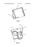
[0011]FIG. 1 is an isometric view of the shelf.
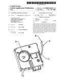
[0012]FIG. 2 is an isometric view of the ink tank.
DESCRIPTION OF EMBODIMENTS
[0013]The present invention is illustrated in detail below with reference to the accompanying drawings and the embodiment.
[0014]As shown in the figures, a chip position 2 and a locking structure 1a 3 are disposed on a shelf 1, a handle 8, a pressure control valve mechanism for precisely controlling an internal negative pressure, a locking structure 1b 5, a locking structure 2a 6 are disposed on an ink tank 7. The locking structure 1b 5 on the ink tank 7 and the locking structure 1a 3 on the shelf 1 are fitted, so as to realize the connection function. The locking structure 2a 6 on the ink tank 7 is fitted with the printer. The pressure control valve mechanism for precisely controlling the internal negative pressure on the ink tank is a check valve 4 which is composed of a valve membrane, a spring, and a valve body.
User Contributions:
comments("1"); ?> comment_form("1"); ?>Inventors list |
Agents list |
Assignees list |
List by place |
Classification tree browser |
Top 100 Inventors |
Top 100 Agents |
Top 100 Assignees |
Usenet FAQ Index |
Documents |
Other FAQs |
User Contributions:
Comment about this patent or add new information about this topic:
Images included with this patent application:
 |  |
 |
| Similar patent applications: | |
| Date | Title |
|---|---|
| 2008-10-16 | Cartridge for an inkjet printer with refill docking interface |
| 2009-04-16 | Ink cartridge for an inkjet printer |
| 2010-01-21 | Ink cartridge for inkjet printers |
| 2010-06-17 | Ink cartridge for inkjet printer |
| 2010-10-07 | Ink cartridge, especially for an ink jet printer |
| New patent applications in this class: | |
| Date | Title |
|---|---|
| 2022-05-05 | Liquid container and recording apparatus |
| 2019-05-16 | Ink container for photo-curable ink |
| 2018-01-25 | Authentication chaining by connected devices |
| 2018-01-25 | System for advanced protection of consumable or detachable elements |
| 2018-01-25 | Photopolymerizable inkjet ink |
| Top Inventors for class "Incremental printing of symbolic information" | |
| Rank | Inventor's name |
|---|---|
| 1 | Kia Silverbrook |
| 2 | Akira Nakazawa |
| 3 | Garry Raymond Jackson |
| 4 | Christopher Hibbard |
| 5 | Norman Micheal Berry |