Patent application title: Security barrier
Inventors:
Marjorie S. Knuckey (Redlands, CA, US)
Rosamond U. Hall (Newport Beach, CA, US)
IPC8 Class: AE02D700FI
USPC Class:
405232
Class name: Foundation columnar structure (e.g., pier, pile) process or apparatus for installing
Publication date: 2008-11-06
Patent application number: 20080273927
Inventors list |
Agents list |
Assignees list |
List by place |
Classification tree browser |
Top 100 Inventors |
Top 100 Agents |
Top 100 Assignees |
Usenet FAQ Index |
Documents |
Other FAQs |
Patent application title: Security barrier
Inventors:
Marjorie S. Knuckey
Rosamond U. Hall
Agents:
STETINA BRUNDA GARRED & BRUCKER
Assignees:
Origin: ALISO VIEJO, CA US
IPC8 Class: AE02D700FI
USPC Class:
405232
Abstract:
There is provided a strong, secure, inexpensive see-through security
barrier. The security barrier includes a foundation, wherein at least a
portion of the foundation is underground. The security barrier also
includes a plurality of pipes. Each pipe is integrally formed with the
foundation and extends generally upwardly from the foundation. Each pipe
includes a cylindrical wall having a generally smooth exterior surface
and a rigid lock seam extending about and along the length of the wall.Claims:
1. A security barrier comprising:a foundation, wherein at least a portion
of the foundation is disposed underground; anda plurality of hollow
pipes, each pipe having a pipe end embedded within the foundation such
that each pipe extends generally upwardly from the foundation, each pipe
being of single piece construction, wherein each pipe includes a
cylindrical wall having a generally smooth exterior surface and a joint
extending helically about and along the length of the wall.
2. The security barrier of claim 1, wherein the joint is a rigid lock seam.
3. The security barrier of claim 1, wherein the foundation is comprised of concrete.
4. The security barrier of claim 1, wherein the foundation is comprised of a plurality of sub-foundations.
5. The security barrier of claim 1, wherein the plurality of pipes are comprised of metal.
6. The security barrier of claim 5, wherein the plurality of pipes are comprised of 12 gauge steel.
7. The security barrier of claim 1, wherein the plurality of pipes are comprised of a plastic material.
8. The security barrier of claim 1, wherein the plurality of pipes are generally evenly spaced apart.
9. The security barrier of claim 8, wherein the distance between the centers of adjacent pipes is approximately two to four feet apart.
10. The security barrier of claim 1, wherein each pipe is at least partially filled with concrete.
11. The security barrier of claim 1, further comprising rebar integrally formed with the foundation and each pipe, the rebar being operative to enhance the strength of the barrier.
12. The security barrier of claim 1, further comprising expanded metal coupled to and extending between at least two pipes.
13. A method of forming a security barrier, the method comprising the steps of:(a) excavating a base;(b) placing a hollow pipe within the base such that each pipe extends generally upwardly from the base, wherein each pipe includes a cylindrical wall having a generally smooth exterior surface and a joint extending helically about and along the length of the wall; and(c) forming a foundation within the base, such that the pipe end is embedded within the foundation.
14. The method of claim 13, wherein the joint is a rigid lock seam.
15. The method of claim 13, wherein the foundation is comprised of concrete.
16. The method of claim 13, wherein the foundation is comprised of a plurality of sub-foundations.
17. The method of claim 13, wherein the pipe is comprised of metal.
18. The method of claim 17, wherein the pipe is comprised of 12 gauge steel.
19. The method of claim 13, wherein the pipe is comprised of a plastic material.
20. The method of claim 13, wherein the pipe is at least partially filled with concrete.
21. The method of claim 13, wherein the pipe include a pair of apertures formed on opposed sides of the cylindrical wall.
22. The method of claim 21, further comprising the step of inserting rebar through the pair of apertures.
Description:
CROSS-REFERENCE TO RELATED APPLICATIONS
[0001]Not Applicable.
STATEMENT RE: FEDERALLY SPONSORED RESEARCH/DEVELOPMENT
[0002]Not Applicable
BACKGROUND
[0003]This invention relates in general to a security barrier. More specifically, this invention relates to a strong, secure, inexpensive security barrier and method of forming the same.
[0004]Security barriers are well known and are in wide use. A security barrier may be constructed to isolate or secure a specified area. Security barriers may also be used to restrict access into and out of regulated areas. The size and strength of each security barrier will depend on the particular security application. In the case of smaller parcels of land, a traditional fence may be an appropriate security barrier to keep unauthorized people of animals off of the property. Examples of traditional fences include chain-link fences, stone-wall fences, electric fences, and split rail fences to name a few. However, if the purpose of the security barrier is aimed at preventing unauthorized vehicles from entering the property, a much more durable barrier is needed. In that case, a reinforced brick or cement wall may be constructed. When larger parcels of land are involved, it may be too costly and time consuming to construct one of the aforementioned barriers along the perimeter of the property, especially in the case of vehicular barriers.
[0005]In today's day and age, where national security and illegal immigration are important issues, it is important to prevent people from freely crossing a nation's borders without authorization. It is particularly important to control people from freely driving a vehicle across the border. Unauthorized vehicles may be transporting illegal immigrants, illegal drugs and/or illegal firearms and/or weapons.
[0006]Although there may be security checkpoints along most of the major boarder crossings, someone may be able to drive across the boarder in a remote location. Therefore, it may be desirable to construct a security barrier along the entire boarder. However, as was mentioned above, when larger areas of land are involved, traditional fences may be too costly and time consuming to construct. In addition, many traditional fences may not be strong enough to prevent a moving vehicle from crossing the border. For instance, a vehicle may easily drive through a slit rail or chain link fence.
[0007]It is therefore evident that there exists a need in the art for a strong, secure, inexpensive and see-through security barrier.
BRIEF SUMMARY
[0008]According to an aspect of the present invention, there is provided a strong, secure, inexpensive see-through security barrier. The security barrier includes a foundation, and/or anchor, at least a portion of which is disposed underground. The security barrier also includes a plurality of hollow, generally smooth conventional metal pipes. Each pipe includes a pipe end embedded within the foundation such that the pipe extends generally upwardly from the foundation. The pipes are of single piece construction, wherein each pipe includes a cylindrical wall having a generally smooth exterior surface and a joint extending helically about and along the length of the wall.
[0009]The present invention provides a strong and inexpensive alternative to traditional fences or security barriers. The security barrier may be constructed easily and quickly along an area in which a security barrier is desirable. The present invention may be used to prevent vehicle from freely crossing the barrier. In addition, the security barrier may be used to prevent people from walking across the barrier.
[0010]It is contemplated that the pipes are comprised of a strong, durable material. As such, the pipes may be comprised of metal, plastic or a similar material known by those skilled in the art. In one embodiment of the invention, the pipes may be comprised of 12 gauge steel to provide sufficient strength and durability.
[0011]Each pipe is integrally formed with the foundation. The foundation is comprised of a strong durable material. Therefore, in one embodiment, the foundation may be comprised of concrete. The strength of the security barrier may also be enhanced by at least partially filling each pipe with concrete. Pipes may also be completely filled with concrete to further enhance their strength and rigidity. In a further embodiment, the security barrier may include rebar integrally formed with each foundation and each pipe. The rebar is operative to enhance the strength of the barrier by preventing someone from pulling out the pipe.
[0012]According to various embodiments of the invention, the space between the pipes may vary. The pipes may be generally evenly spaced apart. In addition, the pipes may be spaced such that the center of each pipe is spaced approximately four feet from the center of adjacent pipes. When the pipes are spaced out, the security barrier may include expanded metal coupled to and extending between at least two pipes. However, the security barrier may be configured such that adjacent pipes are contiguous.
[0013]The present invention also includes a method of forming a strong, inexpensive security barrier. The method includes the steps of excavating a base and placing a hollow pipe within the base such that each pipe extends generally upwardly from the base. The method further includes the step of forming a foundation within the base, such that the pipe end is embedded within the foundation.
[0014]The pipe may include a pair of apertures operative to receive a piece of rebar. As such, the method may also include the step of inserting rebar through the apertures to anchor the pipe within the foundation so as to prevent someone from pulling the pipe out of the foundation.
BRIEF DESCRIPTION OF THE DRAWINGS
[0015]These and other features and advantages of the various embodiments disclosed herein will be better understood with respect to the following description and drawings, in which like numbers refer to like parts throughout, and in which:
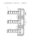
[0016]FIG. 1 is a perspective view of the security barrier;
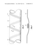
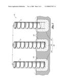
[0017]FIG. 2 is a perspective view of the length of pipe constructed according to the present invention;
[0018]FIG. 3 is a sectional view taken along cutout 3 in FIG. 2;
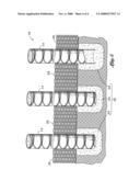
[0019]FIG. 4 is a sectional view of an embodiment of the security barrier, wherein the security barrier includes rebar integrally formed with the foundation and the pipe; and
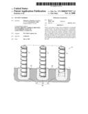
[0020]FIG. 5 is a perspective view of the security barrier, wherein the security barrier includes expanded metal coupled to and extending between at least two pipes.
DETAILED DESCRIPTION
[0021]Referring now to the drawings wherein the showings are for purposes of illustrating a preferred embodiment of the present invention only and not for purposes of limiting the same, FIG. 1 illustrates a strong, secure, inexpensive see-through security barrier 10. The security barrier 10 is comprised of generally smooth wall conventional metal pipe 14, preferably galvanized, having a cylindrical wall 16 and joint 18 extending helically about and along the length of the wall 16. The joint 18 may be a lock seam or welded seam. Each pipe 14 is of single piece construction, and preferably has a diameter of approximately twelve inches, although, it is understood that pipes having other diameters may also be used. The pipe 14 may be constructed on site by a portable pipe mill, or off site at a manufacturing facility.
[0022]The security barrier 10 also includes a foundation 12, wherein at least a portion of the foundation 12 is disposed underground. The foundation 12 is formed of a strong, rigid material. Preferably, the foundation 12 is a concrete in-situ foundation. However, other materials known by those skilled in the art may also be used. Each pipe 14 includes a pipe end embedded within the foundation 12 such that each pipe 14 extends generally upwardly from the foundation 12. As used herein, the pipes 14 extend generally upwardly when the free end of the pipe 14 is elevated from the surface of the ground. The free end of the pipe 14 refers to the end not integrally formed with the foundation 12.
[0023]In the embodiment shown in FIG. 1, the pipes 14 are generally perpendicular to the ground. However, it is understood that in other embodiments, the pipes 14 may not be generally perpendicular to the ground. This is particularly true when the security barrier 10 is located on a terrain having an undulating surface. In that case, the plurality of pipes 14 may be arranged such that they are generally parallel to each other. As such, the plurality of pipes 14 may not be generally perpendicular to the ground. Instead, each pipe 14 may form an obtuse or acute angle with the surface of the ground, depending on the slope.
[0024]As was mentioned above, each pipe 14 extends generally upwardly from the foundation 12. The foundation 12 provides structural stability to the security barrier 14. At least a portion of the foundation 12 is disposed underground. Therefore, before the security barrier 10 can be formed, a base 23 must be formed by sub-grade excavation. The base 23 is the area in which the foundation is formed. As such, the base 23 must have a diameter at least equal to the diameter of the pipes 14. Preferably, the diameter of the base 23 is greater than the diameter of the pipe 14. Once the base 23 is excavated, the pipe 14 and foundation 12 may be placed and formed therein.
[0025]According to one embodiment, the foundation 12 is disposed completely underground. In other words, no part of the foundation 12 is exposed; it is completely buried. In order to create a foundation 12 that is completely underground, the excavated base 23 containing the foundation 12 must be back-filled so as to completely cover the foundation 12. In another embodiment, the foundation 12 extends partially above-ground. As such, the base 23 is excavated within the ground, and the foundation 12 is formed such that it extends above the surface of the ground. In still another embodiment, the foundation 12 is flush with the surface of the ground, as shown in FIG. 1.
[0026]In accordance with yet another embodiment of the invention, the foundation 12 is one, continuous formation that extends along the entire security barrier 10. This may be particularly beneficial in smaller applications. For example, it may be desirable to construct a security barrier 10 along the perimeter of an individual's property to ensure that no vehicles accidentally drive onto the property. As such, one continuous base 23 is excavated around the perimeter of the individual's property and the foundation 12 is formed therein.
[0027]In another embodiment, the foundation 12 is comprised of a plurality of sub-foundations 24, as is shown in FIG. 1. In the case of a plurality of sub-foundations 24, a base 23 must be excavated for each sub-foundation 24. This may be particularly useful in large-scale applications. For instance, if a security barrier 10 is constructed along the border between two countries, it would be difficult to excavate a continuous base 23 along the entire boarder. An alternative is to excavate several smaller bases 23 for sub-foundations 24 to be formed therein. In one embodiment, there is one pipe 14 extending generally upwardly from each sub-foundation 24, as is shown in FIG. 1. This may be beneficial if the pipes 14 are spaced apart from each other by a couple feet. However, in another embodiment, there may be a number of pipes 14 anchored within each sub-foundation 24. For example, there may be three pipes 14 extending from each sub-foundation 24. In this case, if the center of each pipe 14 is spaced four feet apart from the center of adjacent pipes 14, the sub-foundation 24 would extend at least eight feet.
[0028]According to another embodiment, the security barrier 10 further includes rebar 22 to enhance its structural rigidity and strength and also to prevent someone from pulling the pipe 14 out of the foundation 24. FIG. 4 shows an embodiment of the invention including rebar 22. In this embodiment, the pipe 14 includes a pair of apertures formed on opposed sides of the cylindrical wall. The apertures are formed such that the rebar 22 can pass through the pair of apertures. The rebar 22 is integrally formed with the foundation 12 and each pipe 14. It is understood that rebar may be included in individual sub-foundations 24, as well as in one, continuous foundation 12.
[0029]It is contemplated that each pipe 14 is constructed of a strong, rigid material. According to various embodiments, the pipe 14 is constructed of steel in varying gauges. In one particular embodiment, the pipe 14 is constructed of 12-gauge steel. In another embodiment, the pipes 14 are comprised of plastic. Each pipe 14 includes a cylindrical wall 16 and a joint 18 extending helically about and along the length of the wall 16, as is shown in FIGS. 1-2. As shown in the drawings, the joint 18 is preferably comprised of a rigid lock seam. However, it is understood that the joint may also be formed of a welded seam. FIG. 3 is an enlarged partial sectional view showing the lock seam 18. The lock seam 18 is used to form the pipe 14 from rolls of sheeting. In order to expedite the construction of the security barrier 10, the pipes 14 may be assembled prior to construction of the security barrier 10.
[0030]The plurality of pipes 14 may have varying dimensions. For instance, the diameter and length of the plurality of pipes 14 may vary to accommodate different uses of the security barrier 10. Preferably, the pipes 14 are approximately twelve inches in diameter and twelve feet in length. However, pipes 14 having other diameters and lengths may also be used.
[0031]Although the pipes 14 are constructed of a strong, rigid material, the strength or rigidity of the pipes 14 may further be enhanced by at least partially filling the pipes 14 with a strength-enhancing material, such as concrete or other materials known by those skilled in the art. Therefore, in one embodiment of the invention, the pipes 14 are at least partially filled with concrete. The pipes 14 may be completely filled with the strength-enhancing material as is shown in FIGS. 1 and 4, or the pipes 14 may be partially filled. In another embodiment, each pipe 14 is filled with strength enhancing material to a point that is approximately even with the surface of the ground. It should be noted that strength enhancing material is not required, however, it may be added to enhance the structural strength and rigidity of the barrier 10.
[0032]It is envisioned that the present invention may be used in a number of different security applications. The distance between adjacent pipes, shown as A in FIG. 1, can be varied to accommodate a specific use. According to one embodiment, the security barrier 10 is used to prevent humans from crossing the barrier 10. In other words, the security barrier 10 would aim at preventing people from walking through or climbing over the barrier 10. In this embodiment, the pipes 14 are spaced very close together, such that a person cannot pass between adjacent pipes 14. In one particular embodiment, each pipe 14 is contiguous with adjacent pipes 14. In addition, it is important to note that the generally smooth exterior surface of the pipes 14 is aimed at preventing anyone from climbing over the pipes 14.
[0033]Although one embodiment of the invention is used to prevent humans from crossing the barrier 10, another embodiment of the invention is used to prevent vehicles from crossing the barrier 10. Such vehicles may include land vehicles and water vehicles. In one embodiment, the security barrier 10 is constructed on land to prevent land vehicles such as cars, trucks, and other automobiles from passing through the barrier 10. In another embodiment, the security barrier 10 is constructed in a body of water to prevent water vehicles from crossing the barrier 10. This may be particularly useful in areas close to a damn or waterfall. When the primary goal of the security barrier 10 is to prevent vehicles from passing through the barrier 10, it is not necessary to space the pipes 10 as closely as the barrier 10 designed to restrict people. Rather, the distance between adjacent pipes 10 may be increased to a couple feet. However, the pipes 14 must be spaced close enough to prevent vehicles from passing through the barrier 10. In one particular embodiment, the distance between the centers of adjacent pipes 14 is approximately four feet. Although the pipes 14 are separated by a couple feet in one embodiment, the distance between the pipes 14 is as small as a few inches in another embodiment.
[0034]According to another implementation, the placement and arrangement of the pipes may be staggered. Such a staggered arrangement creates a more aesthetically pleasing appearance.
[0035]In another embodiment of the invention, the security barrier 10 includes expanded metal 26 coupled to and extending between adjacent pipes 14, as can be seen in FIG. 5. The expanded metal 26 may be quickly welded or otherwise affixed to the pipes 14 to provide an additional level of protection. The expanded metal 26 includes a plurality of apertures. As such the expanded metal 26 provides a physical barricade, while at the same time allows someone to see through the barrier 10. The expanded metal 26 may extend to the top of the pipe 14, or it may extend only partially along the length of the pipe 14. In the embodiment shown in FIG. 5, the expanded metal 26 extends only partially along the length of the pipe 14.
[0036]In addition to the foregoing, there is also provided a method for forming a security barrier 10. The method includes excavating a base 23. The base 23 is formed by digging a hole or trench in the ground. After the base 23 is excavated, the pipe 14 is placed therein, such that the pipe 14 extends generally upwardly from the base 23. Once the pipe 14 is so situated, the foundation is formed within the base. As was mentioned above, the foundation is preferably formed of concrete or a similar material. The concrete is poured into the base 23. As the foundation 12 hardens or cures, the pipe 14 is integrally formed within the foundation 12.
[0037]According to one embodiment of the present invention, the method also includes the step of integrally forming rebar 22 within the foundation 12 and the pipe 14. In this embodiment, the pipe 14 includes a pair of apertures operative to receive the rebar 22. The rebar 22 is inserted through the apertures before the foundation 12 is poured into the base 23. After the foundation 12 hardens, the rebar 22 is integrally formed with the foundation and the pipe 14.
[0038]The above description is given by way of example, and not limitation. Given the above disclosure, one skilled in the art could devise variations that are within the scope and spirit of the invention disclosed herein. Further, the various features of the embodiments disclosed herein can be used alone, or in varying combinations with each other and are not intended to be limited to the specific combination described herein. Thus, the scope of the claims is not to be limited by the illustrated embodiments.
User Contributions:
comments("1"); ?> comment_form("1"); ?>Inventors list |
Agents list |
Assignees list |
List by place |
Classification tree browser |
Top 100 Inventors |
Top 100 Agents |
Top 100 Assignees |
Usenet FAQ Index |
Documents |
Other FAQs |
User Contributions:
Comment about this patent or add new information about this topic:
| People who visited this patent also read: | |
| Patent application number | Title |
|---|---|
| 20110153786 | Method for offline servicing of a field device of automation technology |
| 20110153785 | Method and Apparatus for Obtaining Digital Objects in a Communication Network |
| 20110153784 | INFORMATION PROCESSING APPARATUS AND METHOD FOR CONTROLLING THE SAME |
| 20110153783 | APPARATUS AND METHOD FOR EXTRACTING KEYWORD BASED ON RSS |
| 20110153782 | Coding data streams |
Images included with this patent application:
 |  |
 |  |
 |
| Similar patent applications: | |
| Date | Title |
|---|---|
| 2009-02-05 | Fixed security barrier |
| 2012-01-05 | Fish guidance and exclusion barrier |
| 2012-06-28 | Self-actuating storm surge barrier |
| 2012-06-28 | Super elevation surface self-actuating flood barrier |
| New patent applications in this class: | |
| Date | Title |
|---|---|
| 2016-06-30 | Helical pile assembly with top plate |
| 2016-06-09 | Pile comprising a substantially cylindrical shaft |
| 2016-05-05 | Pile driving machine |
| 2016-04-21 | Pile installation without extraction |
| 2016-04-21 | Pre-assembled timber piling |
| Top Inventors for class "Hydraulic and earth engineering" | |
| Rank | Inventor's name |
|---|---|
| 1 | Joop Roodenburg |
| 2 | Thomas P. Taylor |
| 3 | Michael Tjader |
| 4 | Keith K. Millheim |
| 5 | John G. Oldsen |