Patent application title: Device For Transporting Containers
Inventors:
Giuseppe Monti (Pianoro (bologna), IT)
Assignees:
MARCHESINI GROUP S.p.A.
IPC8 Class: AB65G2902FI
USPC Class:
1984631
Class name: Conveyors: power-driven conveyor system for moving a specific load as a separate unit
Publication date: 2008-11-06
Patent application number: 20080271976
Inventors list |
Agents list |
Assignees list |
List by place |
Classification tree browser |
Top 100 Inventors |
Top 100 Agents |
Top 100 Assignees |
Usenet FAQ Index |
Documents |
Other FAQs |
Patent application title: Device For Transporting Containers
Inventors:
Giuseppe Monti
Agents:
WILLIAM J. SAPONE;COLEMAN SUDOL SAPONE P.C.
Assignees:
MARCHESINI GROUP S.P.A.
Origin: BRIDGE PORT, CT US
IPC8 Class: AB65G2902FI
USPC Class:
1984631
Abstract:
The device for transporting containers comprises a cogged belt which
extends along a ring-wound trajectory and is wound on at least a pair of
cogged wheels which are rotatable on vertical axes, and a plurality of
regularly distanced support means borne on the external surface of the
cogged belt, which receive respective containers. The cogged belt bears a
plurality of skates constrained to the internal surface thereof which
engage with guide means that are solidly restrained to a fixed structure
of the device, in order to constitute a lateral constraint which prevents
transversal movements and deformation of the cogged belt.Claims:
1. A device for transporting containers of a type comprising a cogged belt
which develops along a ring-wound trajectory and is wound about at least
a pair of cogged wheels rotatable on vertical axes, and a plurality of
regularly distanced support means borne on an external surface of the
cogged belt, which support means receive containers to be transported,
characterized in that fixed to an internal surface thereof the cogged
belt exhibits a plurality of skates which engage with guide means
integral to a fixed structure of the device, in such a way that at least
one lateral constraint is provided to prevent transversal shifting and
deformation of the cogged belt.
2. The device of claim 1, characterized in that the skates are constrained to the cogged belt at positions corresponding to respective support means of the containers.
3. The device of claim 2, characterized that the skates are constrained to the respective support means of the containers by interposing of prism-shaped elements shaped according to a geometric profile of the cogs of the cogged belt.
4. The device of claim 3, characterized in that the prism-shaped elements are solidly constrained to the cogged belt) by screw means which engage with corresponding nut screws realized on the prism-shaped elements, the prism-shaped elements being destined to fasten the support means to the cogged belt.
5. The device of claim 4, characterized in that the nut screws fit in corresponding holes afforded in the cogged belt at sections of the cogged belt which exhibit a flat area in place of cogs.
6. The device of claim 1, characterized in that the guide means comprise a pair of prism-shaped members respectively upper and lower, between which a groove is defined which is parallel to the direction of advancement of the cogged belt and which is delimited by relative reciprocally-facing flat surfaces of the prism-shaped members.
7. The device of claim 6, characterized in that each of the skates is constituted by a prism-shaped block, which extends transversally to the cogged belt and engages slidingly with the groove of the guide means.
8. The device of claim 7, characterized in that the prism-shaped block exhibits a threaded blind-hole for coupling with a screw which screw projects from each of the skates and couples with a washer acting on a side of the guide means in order to prevent transversal shifting of the skates.
9. The device of claim 1, characterized in that the cogged wheels afford an annular groove in the external surface of the cogged wheels in a substantially median position of a height of the cogged wheels; the annular groove being of a sufficient size to contain the skates which circulate fixed to the internal surface of the cogged belt.
Description:
BACKGROUND OF THE INVENTION
[0001]This invention concerns a cogged belt device for in-line transport of containers, in particular, vials, rigid tubes and the like.
[0002]In-line transport systems for containers, in particular, vials and the like, are known at present which are destined for use in automatic machines for filling and packing such containers. Transport systems of this type substantially comprise a pair of vertical-axis cogged wheels on which a cogged belt is wound which can translate in a horizontal direction, drawn by the cogged wheels. The cogged belt conveys a plurality of containers housed inside respective support means which are constrained to the cogged belt at regularly distanced positions.
[0003]In particular, in a known technical solution, the support means exhibit a shaped portion which forms a horizontal support plane for the container, and a pair of appendages which laterally surround the container, thus retaining the container in a transport position. The shaped portions are constrained to the external side of the cogged belt by means of suitable screw means.
[0004]The screw means suitably engage with corresponding nut screws afforded in prism-shaped elements shaped according to a geometric profile of the cogs of the cogged belt and arranged in such a way as to replace some cogs. In effect, at the zones of application of the support means of the containers, the cogged belt exhibits on its internal side respective false cogs consisting of the elements which constrain the support means of the containers.
[0005]Transport systems of the type described are constructively and functionally simple, since they make it possible to obtain transport lines of diverse types and geometric conformation which easily adapt to different operational requirements.
[0006]However, a frequent criticism is that the weight of the containers housed in the support means along the belt may induce lateral torsional stress in the belt. This stress deforms the belt, which thus deviates from the vertical operating configuration for which it is designed. Deformation causes wear, alignment problems for the operating organs of the machine and further damage to the plant.
[0007]Obviously the effects of the drawback described may be more or less serious according to the thickness, width and flexibility of the belt, the weight and dimensions of the containers transported, and the distance between the cogged wheels.
SUMMARY OF THE INVENTION
[0008]The aim of this invention is to obviate the aforementioned drawback by providing a device for in-line transport of containers which makes it possible to avoid torsional deformation of the cogged belt.
[0009]A further aim of the invention is to provide a constructively and functionally uncomplicated transport device which is highly reliable in operation, versatile in use, and relatively inexpensive.
[0010]The abovementioned aims are achieved by means of a device for transporting containers of a type comprising a cogged belt which develops along a ring-wound trajectory and is wound about at least a pair of cogged wheels rotatable on vertical axes, and a plurality of regularly distanced support means borne on an external surface of the cogged belt, which support means receive containers to be transported, characterized in that fixed to an internal surface thereof the cogged belt exhibits a plurality of skates which engage with guide means integral to a fixed structure of the device, in such a way that at least one lateral constraint is provided to prevent transversal shifting and deformation of the cogged belt.
BRIEF DESCRIPTION OF THE DRAWINGS
[0011]The characteristics of the invention are outlined below, with particular reference to the appended tables of drawings, in which:
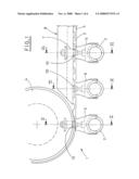
[0012]FIG. 1 shows a plan view of a portion of the transport device of the invention;
[0013]FIG. 2 shows an exploded axonometric view of a detail of the transport device;
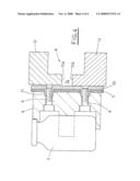
[0014]FIG. 3 shows a vertical section view of the transport device along the plane III-III, the section line of which is indicated in FIG. 1;
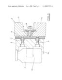
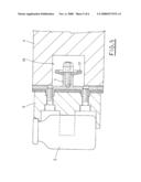
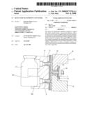
[0015]FIGS. 4 and 5 respectively show a vertical section view of the transport device along the planes IV-IV and V-V in FIG. 1;
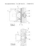
[0016]FIGS. 6 and 7 respectively show a plan view and a corresponding vertical section view of a different embodiment of the transport device of the invention.
[0017]In the figures the reference number 1 refers to the device for in-line transport of containers 2 such as vials and the like, in its entirety.
DESCRIPTION OF THE PREFERRED EMBODIMENTS
[0018]The device 1 is installed on a fixed structure not illustrated in the appended drawings. The fixed structure rotatably supports at least a pair of cogged wheels 4, which lie in the same horizontal plane and are keyed to respective vertical shafts. The cogged wheels 4 are turned in a known way.
[0019]A cogged belt 5 wound on the cogged wheels 4 is provided on an internal surface thereof with a series of cogs 3 having a straight profile matching that of the cogs of the cogged wheels 4. The cogged belt 5 is translated in a horizontal plane, drawn by the cogged wheels 4.
[0020]A plurality of regularly distanced support means 6, which receive respective containers 2 to be transported, are constrained to the external surface of the cogged belt. In a known way, the support means 6 are constituted by a shaped portion which forms a horizontal support plane 6a for the container 2, and by a pair of appendages 6b which laterally surround the container and block it in the transport position.
[0021]The supports 6 are solidly constrained to the cogged belt 5 by screw means 9 which engage with corresponding nut screws 31 afforded in prism-shaped elements 30 shaped according to the geometric profile of the cogs 3 of the cogged belt 5 and arranged in place of respective cogs (see FIG. 4). The screw means 9 tighten the belt 5 between the supports 6 and the false cogs defined by the prism-shaped elements 30.
[0022]In the present invention, the cogged belt 5 bears a series of skates 7, applied on the internal surface thereof, which engage with guide means 8 which are solidly constrained to the fixed structure. The guide means 8 are arranged at least near the operational portion of the trajectory of the cogged belt 5 along which the containers Z are to be transported.
[0023]The guide means 8 are formed by a pair of prism-shaped members 12, 13, respectively upper and lower, between which a groove 14 is defined, which is parallel to the advancement direction of the cogged belt 5 and delimited by relative plane surfaces 12a, 13a facing each other (FIG. 4).
[0024]The skates 7 are each constituted by a prism-shaped block, substantially a parallelepiped-shaped block, which extends from a prism-shaped element 10 shaped like the geometric profile of the cogs 3 of the cogged belt 5, similarly to the abovementioned false cogs 30 (FIG. 2). The skates 7 are destined to engage in the groove 14 of the guide means 8, as will be fully explained herein below.
[0025]Similarly to the false cogs 30, the prism-shaped elements 10 of the skates 7 are solidly constrained to the cogged belt 5 by means of screw means 9 for fixing relative supports 6; the screw means 9 engage with corresponding nut screws 11 realized on the prism-shaped elements 10 (FIG. 3). The nut screws 11 fit into corresponding holes 15 afforded in the cogged belt 5 in sections 5a exhibiting a flat area in place of the cogs 3 (FIG. 2).
[0026]The skates 7 further exhibit a threaded blind hole for coupling with a screw 16 projecting from each of the skates 7. A circular washer 17 is inserted on the screw 16 and tightened against the relative skate 7 by means of a nut 18 (see FIGS. 2 and 3).
[0027]The cogged wheels 4 are of the cylindrical type with straight cogs, of a sufficient height to contain the width of the cogged belt 5. The wheels 4 exhibit an annular groove 19 afforded in the external surface thereof at a substantially median position of the height of the cogged wheels 4, which annular groove is of a sufficient size to contain the skates 7, which circulate fixed to the internal surface of the cogged belt 5 (FIG. 5).
[0028]The functioning of the described device for transporting containers is quite simple to comprehend.
[0029]In operating configuration, the skates 7 associated to the cogged belt 5 on the internal surface thereof engage slidingly with the groove 14 defined by the guide means 8 associated to the fixed structure. The washers 17, constrained respectively to the skates 7, ensure correct positioning of the skates 7, in particular preventing displacements thereof transversally of the guide means 8.
[0030]Thus the skates 7 constitute a lateral constraint for the cogged belt 5, which is therefore constantly maintained in a perfectly vertical position during operation. In this way, possible deformations of the cogged belt 5 are prevented, in particular when the containers 2 to be transported at the various operating stations of the machine are placed on the supports 6.
[0031]Note that when the skates 7 pass nearby the cogged wheels 4, the skates 7 are positioned inside the annular groove 19, thus avoiding interference.
[0032]FIGS. 6 and 7 illustrate a different embodiment of the transport device in which the task of providing a lateral constraint for the cogged belt 5 in order to prevent possible deformation is performed by skates 27 borne projectingly by the prism-shaped elements 10 and fixed on the internal surface of the cogged belt 5 as described above; the skates 27 contribute to supporting the weight bearing down on the belt.
[0033]The skates 27 are constrained to screws 26 coupled to the prism-shaped elements 10 and are blocked by corresponding nuts 28. The skates 27 slide in a groove 24 afforded in the guide means 8.
[0034]The device of the invention for transporting containers achieves the aim of ensuring correct motion of the cogged belt, preventing deformation or shifting due to the torsional stress caused by the weight of the containers transported.
[0035]Note that this result is simply and effectively achieved by using skates 7, 27, which engage with a suitable groove 14, 24 defined by the guide means 8 which are provided near the sections of the trajectory of the cogged belt 5 involved in transport of the containers 2.
[0036]A distinctive feature of the transport device of the invention consists in the fact that the skates 7, 27 are solidly constrained to the cogged belt 5 in an opposite position to a part of the supports 6 of the containers 2. In particular, this fastening is obtained by means of false cogs 10 structurally similar to the false cogs 30 normally used to attach the supports 6 to the containers.
[0037]The cogged belt 5 has a series of flat areas 5a at predetermined intervals on the internal surface thereof, at which flat areas 5a the false cogs 10, 30 are applied. Supports 6 for the containers 2 are fixed to the false cogs 10, 30, a part of which supports 6 further support the skates 7, 27.
[0038]Of note is the fact that the transport device of the invention does not require modifications to the traditional bulk of machines and provides wide-ranging versatility in use in relation to the various operating requirements of automatic machines handling containers such as vials and the like.
[0039]The above description is intended as a non-limiting example, and any constructional variants should be considered as entering within the ambit of protection of the technical solution described above and in the following claims.
User Contributions:
comments("1"); ?> comment_form("1"); ?>Inventors list |
Agents list |
Assignees list |
List by place |
Classification tree browser |
Top 100 Inventors |
Top 100 Agents |
Top 100 Assignees |
Usenet FAQ Index |
Documents |
Other FAQs |
User Contributions:
Comment about this patent or add new information about this topic:
Images included with this patent application:
 |  |
 |  |
 |  |
 |
| Similar patent applications: | |
| Date | Title |
|---|---|
| 2013-07-04 | Device and method for the transfer of container fittings |
| 2011-01-20 | Device for testing substrates |
| 2011-09-29 | Device for sorting products |
| 2013-05-23 | Device for sorting products |
| 2013-07-04 | Electronic device transfer apparatus, electronic device handling apparatus, and electronic device testing apparatus |
| New patent applications in this class: | |
| Date | Title |
|---|---|
| 2016-06-09 | Stacked-roller belt conveyor with zone control |
| 2016-03-24 | Conveyor for transporting objects |
| 2016-03-10 | Conveyor device for loading or unloading piece goods which can be singulated |
| 2014-07-03 | Multiple parts moving system capable of moving parts individually |
| 2014-05-29 | Rectangular thin panel conveyance unit |
| New patent applications from these inventors: | |
| Date | Title |
|---|---|
| 2022-07-21 | A sterilisation tunnel of pharmaceutical containers |
| 2021-12-09 | Method for introducing articles into packs |
| 2017-05-18 | Apparatus for introducing articles into packs |
| 2014-06-26 | Method for removing a sealing film from a container and a device for actuating the method |
| 2014-06-19 | Packing apparatus in a sterile environment with a loading and supply system of articles |
| Top Inventors for class "Conveyors: power-driven" | |
| Rank | Inventor's name |
|---|---|
| 1 | Matthew L. Fourney |
| 2 | Miguel Angel Gonzalez Alemany |
| 3 | Clifford Theodore Papsdorf |
| 4 | Wouter Balk |
| 5 | Uwe Schneider |