Patent application title: Suspension for a wheel of a motor-vehicle, in particular a bus
Inventors:
Maurizio Baroni (Chiari, IT)
Claudio Mondini (Erbusco, IT)
IPC8 Class: AB60G1127FI
USPC Class:
280124157
Class name: Running gear suspension arrangement fluidic suspension
Publication date: 2008-10-23
Patent application number: 20080258419
Inventors list |
Agents list |
Assignees list |
List by place |
Classification tree browser |
Top 100 Inventors |
Top 100 Agents |
Top 100 Assignees |
Usenet FAQ Index |
Documents |
Other FAQs |
Patent application title: Suspension for a wheel of a motor-vehicle, in particular a bus
Inventors:
Maurizio Baroni
Claudio Mondini
Agents:
KIRSCHSTEIN, OTTINGER, ISRAEL;& SCHIFFMILLER, P.C.
Assignees:
Origin: NEW YORK, NY US
IPC8 Class: AB60G1127FI
USPC Class:
280124157
Abstract:
In a suspension for a wheel of a motor-vehicle, supporting, through a
corresponding articulated spindle, V-shape arms, receiving a spring
forming resilient cushioning element thereon the motor vehicle body
bears, the resilient cushioning element comprises a base bearing on
parallel guides of the V-shape arms, thereby forming a bearing surface,
the central guide including a hole for receiving a throughgoing clamping
screw for clamping the resilient cushioning element at a target position.Claims:
1. A suspension for a wheel (1) of a motor vehicle, in particular a bus,
supporting, through a corresponding articulated spindle (6), V-shape arms
(4, 7), said arms (4, 7) supporting a resilient spring forming cushion
element (9), thereon a body of said motor vehicle bears, characterized in
that said resilient cushion element (9) comprises a base (18) bearing on
parallel guides (15, 16, 17) forming a bearing surface, and that a
central guide (15) of said guides comprises a hole (10) for receiving a
throughgoing clamping screw for clamping said resilient cushion element
(9) at a target position.Description:
BACKGROUND OF THE INVENTION
[0001]The present invention relates to a suspension for a wheel of a motor-vehicle, in particular a bus.
[0002]The above mentioned suspension conventionally comprises quadrilateral mechanisms, also commercially called "MultiLink" mechanisms.
[0003]The above suspensions, to be used in particular for supporting motor-vehicle bodies, such as a bus body, are designed for decoupling the movements of the corresponding wheel from those of the vehicle bodywork, thereby leveling out and absorbing bunks and unevenness of a rod mantle.
[0004]Said suspensions generally comprise a wheel assembly, mechanical coupling elements and elastic or resilient coupling elements.
[0005]The above construction assemblies are strictly related with one another to provide a controlled and proper rolling and perfect braking of the wheel assembly, and moreover a perfect kinematic arrangement of the mechanical coupling elements and said wheel assembly and, finally, properly fit and level out the unevenness of the road mantle, through resilient coupling elements.
[0006]Said mechanical coupling elements usually comprise a V-shape arm which, at a joining point thereof, is connected to the wheel support by an articulated spindle.
[0007]The prior art teaches moreover to arrange between the motor vehicle body and the top V-shape arm of the suspension, a spring body, generally a resilient cylindric body.
[0008]Said resilient or elastic body, in particular, is coupled in a per se known manner to the top V-shape arm through a threaded connection, by using, for example, a screw in element.
[0009]Since the resilient performance of a motor vehicle suspension depends, the spring stiffness being the same, on its accurate location along the suspension V-shape arm, it was heretofore necessary to provide several suspension assemblies which, from a mechanical standpoint, were so designed as to precisely meet the requirements of a target motor vehicle.
[0010]This requirement required the provision of different suspension assemblies, thereby increasing both the making storing cost of above devices.
SUMMARY OF THE INVENTION
[0011]Accordingly, the aim of the present invention is to overcome the above mentioned drawbacks of the prior art, and provide a suspension assembly for a wheel of a motor vehicle, in particular a bus, which can be easily fitted to specifical technical requirements of the vehicle.
[0012]According to the present invention, the above aim is achieved by a suspension for a wheel of a motor vehicle, in particular a bus, supporting, through a corresponding articulated spindle, V-shape arms, said arms supporting a resilient spring forming cushion element thereon a motor vehicle body bears, said resilient cushion element having a resilient cushion element base bearing on parallel guides of said V-shape arms forming a bearing surface, a central guide including a hole for receiving a throughgoing clamping screw for clamping said resilient cushion at a target position.
BRIEF DESCRIPTION OF THE DRAWINGS
[0013]The subject matter according to the present invention will be disclosed in a more detailed manner hereinafter and with reference to an embodiment thereof illustrated in the accompanying drawings, where:
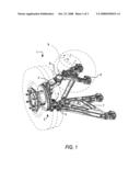
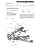
[0014]FIG. 1 is a perspective view showing a wheel of a motor vehicle and related suspension;
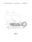
[0015]FIG. 2 shows, partially in a cross-section and partially in a front view, the top arm of the suspension according to FIG. 1; and
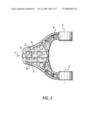
[0016]FIG. 3 is a top plan view showing the two top V-shape arms.
DESCRIPTION OF THE PREFERRED EMBODIMENT
[0017]As shown in FIG. 1, the wheel 1 of a motor vehicle, in particular a bus, is supported by a per se known supporting assembly, generally indicated by the reference 2. The bottom end portion 3 and top end portion 4 of the supporting assembly are coupled, through an articulated spindle 5, respectively 6, to an arm bottom assembly 7 and an arm top assembly 8, which are connected to one another at the corresponding articulated V-shape spindle 5, 6.
[0018]The top arm assembly 8 supports a resilient or elastic element 9 which can comprise, for example, an air cushion element, forming an air spring, on which spring the body (not shown) of the motor vehicle bears.
[0019]In FIG. 2, the top arm, generally indicated by the reference number 8, is partially shown by a front view and partially by a cross-sectional view. The front end portion 8a of said arm 8 comprises a precisely arranged throughgoing hole 10. A clamping screw (not shown) for clamping the cushion element 9 being engageable in said throughgoing hole 10.
[0020]The arm 8 has a rotary axis X, whereas the throughgoing hole 10 is formed through the front portion 8a of the arm 8 and has an axis Y, the letter Z showing a swinging axis.
[0021]FIG. 2 shows the distance A of the swinging axis Z to the rotary axis X. The letter B shows the distance between the axis Y and axis X of the hole 10 for receiving said clamping screw (not shown) for clamping said cushion element 9.
[0022]FIG. 3 further shows the arms 8 of the suspension assembly, said arm 8 being swingable about the axis X, and is moreover herein shown the rotary point Z thereof.
[0023]The front portion 8a of the arms 8 comprises, according to the present invention, on the side thereof facing the cushion element 9, a central guide or sliding block 15, including the throughgoing hole 10.
[0024]The central guide 15, in particular, adjoins a side guide 16 and a further side guide 17.
[0025]Said guides 15, 16 and 17, which are arranged in the same plane, define a suitable bearing surface for the base 18 forming the base portion of said cushion element 9. Said base 18 is advantageously made as a flat plate.
[0026]In this connection it should be apparent that the hole 10 for receiving said clamping screw of said cushion element 9 must be formed at a precise distance B, this position varying depending on the type of the vehicle and on the mechanical stress the vehicle suspension will be subjected to.
[0027]Thus, according to the present invention, said double arm 8 will be made as a standard piece including said guides 15, 16 and 17, but without the hole.
[0028]Only upon knowing the use of the arm 8 and, accordingly, the type of the vehicle the arm 8 must be applied to, depending on technical considerations related to the specific stress on the suspension, it will be possible to define the precise position of the axis Y and the distance B, and, accordingly, the cushion element 9 clamping corresponding hole 10 will be made at this position (which, of course, can change depending on the vehicle).
[0029]Thus, since the arm 8 according to the present invention can be perforated only upon knowing its application depending on the type of the vehicle, it will be possible to use a standard suspension assembly.
User Contributions:
comments("1"); ?> comment_form("1"); ?>Inventors list |
Agents list |
Assignees list |
List by place |
Classification tree browser |
Top 100 Inventors |
Top 100 Agents |
Top 100 Assignees |
Usenet FAQ Index |
Documents |
Other FAQs |
User Contributions:
Comment about this patent or add new information about this topic:
Images included with this patent application:
 |  |
 |  |
| Similar patent applications: | |
| Date | Title |
|---|---|
| 2011-12-01 | Rear suspension for a two-wheel vehicle |
| 2012-10-04 | Suspension system with articulation compliant spring beam bushing |
| 2011-10-20 | Wheel suspension for wheeled vehicles |
| 2012-08-30 | Suspension of a vehicle axle and vehicle |
| 2012-08-30 | Suspension of a vehicle axle and vehicle |
| New patent applications in this class: | |
| Date | Title |
|---|---|
| 2016-06-16 | Position dependent damper for a vehicle suspension system |
| 2016-03-24 | Suspension system |
| 2015-12-03 | Suspension system for motor vehicles |
| 2015-04-30 | Systems and methods for automated air suspension pressure drop |
| 2015-02-26 | Shock absorber gas spring seal |
| Top Inventors for class "Land vehicles" | |
| Rank | Inventor's name |
|---|---|
| 1 | Osamu Fukawatase |
| 2 | Christopher P. D'Aluisio |
| 3 | Richard W. Mccoy |
| 4 | Jun Yeol Choi |
| 5 | Yusuke Fujiwara |