Patent application title: Dispensing Device
Inventors:
Ronald J. Mathis (San Antonio, TX, US)
Assignees:
SOUTHWEST RESEARCH INSTITUTE
IPC8 Class: AA63H2700FI
USPC Class:
446 46
Class name: Amusement devices: toys aerodynamically supported or retarded spinning disc (e.g., flying saucer)
Publication date: 2008-10-16
Patent application number: 20080254705
Inventors list |
Agents list |
Assignees list |
List by place |
Classification tree browser |
Top 100 Inventors |
Top 100 Agents |
Top 100 Assignees |
Usenet FAQ Index |
Documents |
Other FAQs |
Patent application title: Dispensing Device
Inventors:
Ronald J. Mathis
Agents:
GROSSMAN, TUCKER, PERREAULT & PFLEGER, PLLC
Assignees:
SOUTHWEST RESEARCH INSTITUTE
Origin: MANCHESTER, NH US
IPC8 Class: AA63H2700FI
USPC Class:
446 46
Abstract:
The present disclosure relates to a device and method for dispensing a
substance. The device may include a body portion in the shape of an
airfoil and includes a region to contain the substance to be dispensed.
The device may include one or a plurality of ports which may include a
covering having a mechanical strength (e.g. tensile strength) that is
less than the mechanical strength of the body portion. The device may be
launched either by hand or by a launching mechanism.Claims:
1. A dispensing apparatus comprising:a body portion wherein said body
portion is configured in the shape of an airfoil and includes a region to
contain a substance, said body portion formed from a first material
having a tensile strength TS1;one or a plurality of ports in said
body portion wherein said ports are capable of dispensing said
substance;said ports including a covering material having a tensile
strength TS2, wherein TS2<TS.sub.1.
2. The dispensing apparatus of claim 1 wherein TS.sub.1.gtoreq.5000 psi.
3. The dispensing apparatus of claim 1 wherein said region to contain a substance includes a plurality of chambers wherein each chamber is capable of containing a selected substance for dispensing through said ports.
4. The dispensing apparatus of claim 3 wherein said substances when contained in said chambers are capable of exchanging between said chambers.
5. The dispensing apparatus of claim 3 wherein said chambers include wall sections wherein said wall sections are capable of providing diffusion of said substances between said chambers.
6. The dispensing apparatus of claim 1 wherein said body has a perimeter and said region to contain a substance extends about all or a portion of said perimeter.
7. The dispensing apparatus of claim 1 wherein said covering material has a thickness of less than or equal to about 2.5 mm.
8. The dispensing apparatus of claim 1 wherein said covering material is adhered to said apparatus by an adhesive.
9. The dispensing apparatus of claim 1 wherein TS2 is less than about 5000 psi.
10. A dispensing apparatus comprising:a body portion wherein said body portion is configured in the shape of an airfoil and includes a region to contain a substance, said body portion formed from a first material having a tensile strength TS1 of greater than or equal to 5000 psi;one or a plurality of ports in said body portion wherein said ports are capable of dispensing said substance;said ports including a covering material having a thickness of less than or equal to about 2.5 mm having a tensile strength TS2, wherein TS2 is less than 5000 psi.
11. The dispensing apparatus of claim 10 wherein said region to contain a substance includes a plurality of chambers wherein each chamber is capable of containing a selected substance for dispensing through said ports.
12. The dispensing apparatus of claim 11 wherein said substances when contained in said chambers are capable of exchanging between said chambers.
13. The dispensing apparatus of claim 10 wherein said covering material is adhered to said apparatus by an adhesive.
14. A method for dispensing a substance comprising:providing a device having a body portion wherein said body portion is configured in the shape of an airfoil and includes a region containing a substance, said device including one or a plurality of ports in said body portion wherein said ports are capable of dispensing said substance wherein said ports include a covering material adhesively bonded to said body portion and having a tensile strength;rotating said device and developing a tensile force (Tf) on said covering material wherein said tensile force exceeds one of:(a) said tensile strength of said covering material; or(b) said adhesive bond of said covering material to said body;whereupon said substance is dispensed through said ports to a surrounding environment.
15. The method of claim 14 wherein the tensile strength of said covering material is less than about 5000 psi.
16. The method of claim 14 wherein said region to contain a substance includes a plurality of chambers wherein each chamber contains a selected substance for dispensing through said ports.
17. The method of claim 14 wherein said substances in said chambers are capable of exchanging between said chambers.
18. The method of claim 14 wherein said device includes a gas generating substance which produces a gas wherein said gas creates a pressure in said device that contributes to formation of said tensile force (Tf) on said covering material.
Description:
FIELD OF DISCLOSURE
[0001]The present disclosure relates to dispensing device which may release a substance in flight. The device may include one or more chambers to contain the substance and one or a plurality of ports. The device may then release the substance due to physical forces (e.g. centrifugal forces developed in flight) or chemical considerations (e.g. chemical dissolution).
BACKGROUND
[0002]Crowd control, riot control or demonstration control may utilize tactics and special equipment to break up or reduce the aggression of the crowd. Some crowd control methods have included the use of rubber bullets or other projectiles, tasers, batons and other pieces of equipment. In addition, other crowd control methods may include the use of malodorants, pepper spray, tear gas, which may be disseminated via grenades, sprays or bullets. Desirably, the equipment and tactics used minimize harm to those involved, target multiple people at once and prevent additional violence.
SUMMARY
[0003]The present disclosure is directed at a dispensing apparatus comprising a body portion wherein the body portion may be configured in the shape of an airfoil. The body may include a region to contain a substance and the body portion may be formed from a first material having a tensile strength TS1. The body may include one or a plurality of ports in wherein the ports are capable of dispensing the contained substance. The ports may include a covering material having a tensile strength TS2, wherein TS2<TS1.
[0004]In another exemplary embodiment, the present disclosure relates to a dispensing apparatus comprising a body portion wherein the body portion is configured in the shape of an airfoil. The body may again include a region to contain a substance and the body portion may be formed from a first material having a tensile strength TS1 of greater than or equal to 5000 psi. The body portion may then contain one or a plurality of ports wherein the ports are capable of dispensing the contained substance. The ports may include a covering material having a thickness of less than or equal to about 2.5 mm having a tensile strength TS2, wherein TS2 is less than 5000 psi.
[0005]In yet another exemplary embodiment, the present invention relates to a method for dispensing a substance via use of a device having a body portion wherein the body portion is configured in the shape of an airfoil and includes a region to contain a substance. The device may again include one or a plurality of ports in the body portion wherein the ports are again capable of dispensing the contained substance and the ports include a covering material adhesively bonded to said body portion and have an associated tensile strength. The device may then be rotated which may then provide for a tensile force (Tf) on the covering material wherein the tensile force may exceed one of (a) the tensile strength of said covering material; or (b) the adhesive bond of said covering material to said body. At such time the contained substance may be dispensed through the ports to a surrounding environment.
BRIEF DESCRIPTION OF THE DRAWINGS
[0006]Various features and advantages of the present disclosure may be better understood by reading the following detailed description, taken together with the drawings wherein:
[0007]FIG. 1 illustrates a perspective view an exemplary disc including ports on the leading edge for disseminating a crowd control substance contained within a chamber in the disc;
[0008]FIGS. 2a, b, and c illustrate cross-sectional side views of exemplary discs;
[0009]FIGS. 3a and 3b illustrate cross-sectional top views of exemplary discs including ports around the leading edge of the discs;
[0010]FIG. 4a and 4b illustrate a top view and side view, respectively of exemplary port locations for a disc;
[0011]FIG. 5a and 5b illustrate exemplary covering configurations for a disc; and
[0012]FIG. 6 illustrates a cross-sectional side view of exemplary disc and chamber including an exemplary actuation mechanism.
DETAILED DESCRIPTION
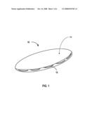
[0013]The present disclosure relates to a device and/or method for disseminating substances which may then be used for crowd control purposes. FIG. 1 illustrates an exemplary device 10 that is capable of rotation with a chamber therein which may hold a crowd control substance (discussed more fully below). The device may therefore be understood as assuming any geometric shape that may rotate about an axis. The device may therefore have a body portion 11 that may have a diameter (largest linear dimension through the device) that may exceed its largest cross-sectional thickness. Accordingly, while the exemplary device is shown having a substantially circular outer peripheral edge, and may be termed a disc, it may be appreciated that it need not be substantially circular and may include, e.g., triangular, square, and/or rectangular type configurations that may also rotate about a given axis. In addition, the walls of the device may then include one or more ports 12 which may allow for the contained substance to pass from the chamber and through the wall and into the surrounding environment.
[0014]The disc may be in the shape of an airfoil having a number of exemplary cross-sections as illustrated in FIGS. 2a, 2b and 2c. An airfoil shape is reference to a configuration which may move through a fluid (e.g. air) and produce a force that may be generally perpendicular to the fluid and which may provide lift. As can be seen in these figures the thickness of a disc 20 may vary along the cross-section. In addition, the upper and lower surfaces 22, 24 of the disc may be convex, flat or concave or a combination thereof. Furthermore, the leading edge 26 of the disc may be rounded, pointed, flat or a combination thereof around the disc circumference.
[0015]The figures also illustrate that the chamber 28 defined within the disc 20 may assume a number of shapes and may be positioned along the outer perimeter and extend inwardly into the device. For example, as seen in FIG. 2a, the chamber 28 may be annular (as viewed from the top) with a circular cross-section. As seen in FIG. 2b, the chamber 28 may be annular (as viewed from the top) with a continuously varying cross-sectional thickness as opposed to a constant thickness which may substantially conform to the exterior shape of the disc. In addition, and as illustrated in FIG. 2c, the chamber 28 may be substantially oval (as viewed from the top) and have an elliptical cross-section. It should therefore be appreciated that any number of configurations of the chamber are contemplated herein and that the above are merely examples of the various configurations that may be utilized.
[0016]Turning to FIGS. 3a and 3b, a cross-sectional top view of the disc 30, illustrates two exemplary embodiments of chambers 32 which may be incorporated into the disc 30. As seen in FIG. 3a, the chamber may extend around the entire perimeter of the disc and have an annular shape. However, in the context of the present disclosure, the chamber may extend around only a portion of the perimeter. Accordingly, the chamber may be positioned at the perimeter and extend about the perimeter from 1-360 degrees, including all values and increment therein.
[0017]In addition, a number of ports 34 may be located in the disc wall 36 which may allow for a number of individual substances to be retained within the chamber 32 for delivery to a surrounding environment 38. Accordingly, the chamber 32 may also be segmented with one or more walls 39 as illustrated in FIG. 3b. The walls 39 may extend for the entire height of the chamber to isolate the segmented portions. The walls 39 may also extend for just a portion of the chamber height allowing for some of the substance retained within the individual chambers to exchange and come in contact with one another (e.g. to pass over the walls). It is also contemplated herein that the walls 39 may also be formed from materials which may allow for a selected amount of diffusion (e.g. liquid diffusion) between the chambers so that substances in the chambers may contact and mix (e.g. when the device is deployed) to thereby provide for a chemical reaction between different substances to provide a formed substance (e.g. a reaction product) for delivery to a selected target.
[0018]The ports allowing for delivery of one or more substances to the surrounding environment of the disc may also be positioned in a variety of locations on the outer disc wall. For example, as illustrated in FIG. 4a, the ports 42 may be located on the bottom or top surface 44 of the disc 40. While the ports are illustrated as being positioned about the periphery of the disc, the ports may be positioned at any point on the disc surface 44. Such placement may depend on the type of substance used in the disc and the type of release mechanism desired. In addition to the above, and as illustrated in FIG. 4b, ports 42 may also be positioned on the leading edge 46 of the disc 40.
[0019]The ports may be covered by one or more materials which may be configured to be responsive to a physical force such that it may release (from the device surface) and/or burst open and dispense the substance contained therein. That is, a material may be provided for a port surface such that the substance contained in the chamber 32 may not be dispensed until desired (e.g., when a given physical force or chemical environment may be realized). Such material may therefore include, e.g. polymeric film material, which may be understood as polymeric material having a thickness of less than or equal to about 2.5 mm. For example, the thickness may be between about 0.1-2.5 mm, including all values and increments therein. The film material may be sourced from a variety of materials such as polymer resins including polyolefins (polyethylene or polypropylene), polyesters, poly(vinyl chloride), poly(vinylidine chloride) copolymers, poly(vinyl alcohol), poly(vinyl alcohol-co-vinyl acetate), polycarbonate, polyurethanes, cellulosic polymers, etc.
[0020]It is also contemplated herein that the above referenced film material may be configured such that it may itself contain the substance that may be stored in any of the exemplary chambers (see again chambers 28 in FIGS. 2a-2c or 32 in FIGS. 3a and 3b.). For example, the film material may then provide a convenient method to load the device 10 with a charge of fluid material for storage in the chambers and also provide the requisite physical or chemical properties so that the film may respond and release the material contained therein when the device is deployed and/or after a given time period.
[0021]A number of mechanisms may therefore be used to release the material from the exemplary chambers. As noted, a physical force may be provided, such as a centrifugal force, which may then impose a tensile force vector on the film material covering a given port. With attention to FIG. 3a, arrow A generally indicates the rotation of the device and the location of a tensile force Tf that may then be provided which may be generally normal (perpendicular) to the port opening and associated film covering 52. Accordingly, when such tensile force Tf exceeds the tensile strength (TS) of a given film covering, the film may break and release the stored substance. In addition, it is contemplated herein that the film covering 52 may be adhered to the device at location 53 by use of a suitable pressure sensitive adhesive. Accordingly, the tensile force Tf that may be developed due to rotation and centrifugal force of a stored substance on the film may be such that the adhesive may release and similarly dispense the substance as desired. Suitable pressure sensitive adhesives contemplated herein include rubber based adhesives (e.g. from styrene-butadiene polymers), acrylics, and silicone polymers.
[0022]In an exemplary embodiment, and as illustrated in FIG. 5a, the film covering 52 may be provided which may cover all of the ports 54 of a disc 50. As noted above, the film 52 may be adhered to the disc and then be released in flight. In another embodiment, the film 52 may be inserted in and cover one or more of the ports as illustrated in FIG. 5b.
[0023]The film covering may also be compromised and release a given substance due to an internal pressure developed within the chamber. In an exemplary embodiment, two or more substances may be provided in the device wherein upon combination a gas may be formed pressurizing the chamber and causing the covering to release (e.g. burst or release from the device surface). For example, an isocyanate compound (RNCO) may be provided in one selected chamber and water may be provided in another chamber reservoir which may come in contact (e.g. during flight and exchange over wall 39 or diffusion through wall 39) to thereby form carbon dioxide gas which may then pressure the chamber 32 and serve to release a film covering 52.
[0024]In a further embodiment, it is contemplated herein that the film covering may be provided with a tear seam or a tear strip, which may be a weakened portion of the covering. Such tear seam or strip may be provided by perforating a portion of the covering or by providing a portion of the covering that is substantially thinner or prone to splitting or prone to tearing along a region of polymer orientation. It may therefore be appreciated that the tear seam or strip may reduce the necessary pressure for breaking the film covering 52.
[0025]Furthermore, it should be appreciated that given the above, the disc may be formed from a material that has a relatively higher tensile strength than the film covering, allowing for the covering to break while still maintaining the integrity of the disc. Accordingly, the disc body may be formed from a polymeric material, or other material having a tensile strength TS1 and the film covering may be formed from a polymeric material, or other material having a tensile strength TS2, wherein TS1>TS2. For example, the body may have a tensile strength of greater than or equal to about 5000 psi, and the film covering may have a tensile strength of less than 5000 psi. More specifically, the film covering may have a tensile strength between 100-5000 psi, including all values and increments therein. It may therefore be appreciated that the body of the device herein may be injection molded and formed from a variety of thermoplastic materials, including polyolefins (polyethylene or polypropylene), acrylonitrile-butadiene-styrene polymers (ABS), aromatic polyesters (e.g. polybutylene terephthalate), nylons, thermoplastic elastomers, thermoset elastomers, etc. In addition, it is contemplated herein that the device may be formed from a polymer resin that may be water soluble and which may therefore dissolve in water when left in the environment after use. For example, the device may be formed from a poly(vinyl alcohol) polymer, or a poly(vinyl alcohol) co-poly(vinyl acetate) resin. It may also be formed from a cellulosic or starch based polymer as well as those polymers that may be susceptible to electromagnetic energy degradation over time.
[0026]In a further embodiment, it is contemplated herein that internal pressure in the chamber may be triggered by the release of a compressed gas, such as air, nitrogen, or carbon dioxide, etc. from a pressurized canister. The canister may be preloaded into the disc and then the gas may be released at the push of a button. Appropriate flow restrictors or timers may be used to time the release, pressurization and breakage of the one or more film coverings. In an additional embodiment, it is contemplated that dry ice or CO2 in a solid state may be added to the disc, which may then be sealed. As the dry ice converts to a gaseous state (sublimes), the chamber may pressurize and a film covering may release.
[0027]Accordingly, as generally illustrated in FIG. 6, an exemplary embodiment of a disc 60 may include an activation mechanism 62 which may include a flexible portion of the disc, such as a depressible button. The activation mechanism 62 may further include a pin 64 which may rupture a reservoir 66 including a first component or release a compressed gas from a canister. In addition, a second reservoir 68 may be provided for a reactive compound, which upon release may react with the first component. Once activated, the chamber of the disc 70 may become pressurized causing a film covering over one or more ports 72 to be compromised and release, wherein a desired substance may then be dispersed through the ports 72.
[0028]The substance contained within the disc may include a crowd control substance such as an irritant, along with a colorant and/or an inert substance. An irritant substance may be understood as one that would cause an inflammatory reaction in an individual, which reaction may vary depending upon concentration and/or time of exposure. The substance may be provided as a powder, beads, flake, liquid, or gel. Exemplary irritants may include tear gas, capsaicin such as Oleoresin capsaicin or other forms of pepper based irritants, malodorants, etc. A colorant may also be included such as a dyes or taggants. Inert substances may include water, volatile solvents (solvents that may evaporate at ambient conditions) or other placebos.
[0029]The disc may be launched by hand, that is thrown with sufficient angular momentum and obtaining some degree of lift, allowing for the disc to travel a desired distance. The disc may also be launched by a launching device which may propel the disc by, once again, providing sufficient angular momentum and obtaining some degree of lift. Accordingly, the disc may include appropriate geometric configurations to accommodate the launching device. When launching the disc, either by hand or by a launching device, the angle of attack or angle at which the disc is thrown may be varied. In addition, the angular momentum applied to the disc may be varied, such that the disc may travel a desired distance.
[0030]The foregoing description is provided to illustrate and explain the present invention. However, the description hereinabove should not be considered to limit the scope of the invention set forth in the claims appended here to.
User Contributions:
comments("1"); ?> comment_form("1"); ?>Inventors list |
Agents list |
Assignees list |
List by place |
Classification tree browser |
Top 100 Inventors |
Top 100 Agents |
Top 100 Assignees |
Usenet FAQ Index |
Documents |
Other FAQs |
User Contributions:
Comment about this patent or add new information about this topic:
Images included with this patent application:
 |  |
 |  |
 |  |
 |
| Similar patent applications: | |
| Date | Title |
|---|---|
| 2012-01-26 | Water dispensing device |
| 2009-01-22 | Hand-gripped clapping device |
| 2012-10-18 | Novelty fish measuring device |
| 2013-08-15 | Protective case for portable electronic device |
| New patent applications in this class: | |
| Date | Title |
|---|---|
| 2015-11-19 | Air cone flyer |
| 2015-03-26 | Flying disk with removable trampoline portion |
| 2015-03-19 | Interlocking flying discs with optional spacer ring |
| 2015-02-05 | Flying disc |
| 2014-10-09 | Stabilized flying disc toy |
| Top Inventors for class "Amusement devices: toys" | |
| Rank | Inventor's name |
|---|---|
| 1 | Robert H. Mimlitch, Iii |
| 2 | David Anthony Norman |
| 3 | Michael Nuttall |
| 4 | Stacy Lynn O'Connor |
| 5 | Joel Reagan Carter |