Patent application title: Package for Two Components
Inventors:
Vladimir Nikolaevich Efremenko (Rostov-Na-Donu, RU)
IPC8 Class: AB65D9002FI
USPC Class:
220669
Class name: Receptacles sidewall structure contoured sidewall (e.g., curved, corrugated, ribbed, variable thickness, etc.)
Publication date: 2008-10-16
Patent application number: 20080251521
Inventors list |
Agents list |
Assignees list |
List by place |
Classification tree browser |
Top 100 Inventors |
Top 100 Agents |
Top 100 Assignees |
Usenet FAQ Index |
Documents |
Other FAQs |
Patent application title: Package for Two Components
Inventors:
Vladimir Nikolaevich Efremenko
Agents:
NOTARO AND MICHALOS
Assignees:
Origin: ORANGEBURG, NY US
IPC8 Class: AB65D9002FI
USPC Class:
220669
Abstract:
The invention covers the packing industry, in particular, a package design
providing a separate packing of different components without their
mixing. The concept of the invention: the package for two components
contains two vessels 1 and 2 connected to each other with external
surfaces of necks 3 and 4. The vessels 1 and 2 are connected with a
connecting cap 5 and closed with membranes 6 and 7. The connecting cap 5
provides a counter-connection of two necks 3 and 4 of the vessels 1 and 2
in such a way that one membrane rests against the other one ensuring
reliable tightness of both vessels.Claims:
1. The package for two components containing two vessels made with
membranes for hermetical encapsulation of internal volumes connected to
each other with external surfaces of necks by means of a connecting cap
characterized in that that the connecting cap is made with grooves on the
internal surface and the neck of one vessel has the lugs on the external
surface for installation of this into the grooves of the connecting cap
and limiting of the turning of this vessel relative to the cap, the neck
of the second vessel is made with the lugs on the external surface to
ensure turning of the mentioned cap and the membrane of each vessel has a
glass-like shape with a closed end part placed inside the vessel and
having a side wall made with edges bent outwards and bearing on the end
surface of the neck of the corresponding vessel, at that, the edges of
the membrane of one vessel bent outwards are placed with resting against
the closed end part of other vessel when the package is assembled.
2. The package for two components containing two vessels made with membranes for hermetical encapsulation of internal volumes connected to each other with external surfaces of necks by means of a connecting cap characterized in that that the connecting cap is made with grooves on the internal surface and the neck of one vessel has the lugs on the external surface for installation of this into the grooves of the connecting cap having a protective cleat against opening and limiting of the turning of this vessel relative to the cap, the neck of the second vessel is made with the lugs on the external surface to ensure turning of the mentioned cap and the membrane of each vessel has a glass-like shape with a closed end part placed inside the vessel and having a side wall made with edges bent outwards and bearing on the end surface of the neck of the corresponding vessel, at that, the edges of the membrane of one vessel bent outwards are placed with resting against the surface of the protective cleat by installation into the grooves of the connecting cap and the connecting cleat is made with possibility of its resting against the closed end part of the membrane of other vessel when the package is assembled.
3. The package for two components containing two vessels made with membranes for hermetical encapsulation of internal volumes connected to each other with external surfaces of necks by means of a connecting cap characterized in that that it is equipped with a protective cleat, connective band with grooves on the internal surface and a safety element, the connecting cap is made with grooves on the internal surface, the necks of each vessel have the lugs on the external surface for installation of these into the grooves of the connecting cap and the connective band accordingly and limiting of the turning of one vessel relative to the cap and the turning of other vessel relative to the connective band accordingly. The band along the external surface is made with lugs to ensure turning of the connecting cap onto this. The membrane of each vessel has a cylindrical shape with one closed end part and one other open end part made with edges bent outwards and bearing on the end surface of the neck of the corresponding vessel and a protective cleat of the connecting cap presses the edge of the membrane to the neck end of one vessel and has a ring for convenient removal of the cleat out of the connecting cap and a safety element of the connective band presses the edge of other membrane to the neck end of other vessel and also has a ring for convenient removal of the safety element out of the connective band.
Description:
ART
[0001]The invention covers the packing industry, in particular, a package design providing a separate packing of different components without their mixing, this can be necessary in various branches of industry, e.g., chemical industry, food industry etc.
PRIOR KNOWLEDGE
[0002]A multisectional cylindrical vessel providing the transportation and storage of at least two heterogeneous materials containing a vessel divided longitudinally into two parts made in form of semi-cylindrical segments (RU No 2127215, B65D 81/32, publ. 10.03.1999) is known.
[0003]The package for two components containing two vessels with membranes for encapsulation of internal volumes connected to each other with external surfaces of necks by means of a connecting cap (U.S. Pat. No. 4,883,935, B65D81/32. publ. 28.11.2989) is the most similar with respect to the technical nature and result obtained for all variants of execution.
[0004]Though the known solution contains a vessel made from two sectional parts connected to each other with external surfaces and solves a problem of a separate tight packing of different components, however, hermetic encapsulation of vessels requires the use of special technologies and special equipment for execution of operations of the rigid permanent fastening of membranes inside of vessels. By such execution the package becomes nonrecoverable and each vessel must be filled with an agent at the factory, what excludes a possibility of its filling with a desirable agent, e.g., in common applications or under any other conditions different from the factory conditions.
DISCLOSURE OF THE INVENTION
[0005]This invention is focused on solving of a technical task to create a package allowing transportation and storage of different components separately before use of them in a mixture, with their protection against opening of the vessel and ensuring a reliable tightness of vessels with their protection against opening of one or both vessels forming a package by providing a possibility of filling of vessels with any agent and under any conditions.
[0006]The technical result reached by use of this invention consists in the improvement of functional properties of the package for two components without their mixing providing the maintaining of its tightness by storage and the possibility of nonexpendable use.
[0007]The mentioned technical result for the first variant can be reached by that that the package is made with a connecting cap with grooves on the internal surface and membranes covering each vessel, at that the neck of one vessel has lugs on the external surface for installation of this into the grooves of the connecting cap and for limitation of turning of this vessel relative to the cap. The neck of the second vessel is made with lugs on the external surface to ensure turning of the mentioned cap and a membrane of each vessel has a cylindrical shape with one closed end part and one other open end part made with edges bent outwards and bearing on the end surface of necks of the corresponding vessel.
[0008]The mentioned technical result for the second variant can be reached by that that the package is made with a connecting cap with grooves on the internal surface and membranes covering each vessel, at that the neck of one vessel has lugs on the external surface for installation of this into the grooves of the connecting cap having a protective cleat. The neck of the second vessel is made with lugs on the external surface to ensure turning of the mentioned cap and a membrane of each vessel has a cylindrical shape with one closed end part and one other open end part made with edges bent outwards and bearing on the end surface of necks of the corresponding vessel.
[0009]The mentioned technical result for the third variant can be reached by that that the package is made with a connecting cap with grooves on the internal surface and a protective cleat, a connective band with grooves on the internal surface and a safety element, membranes covering each vessel, at that the necks of each vessel have lugs on the external surface for installation of these into the grooves of the connecting cap and connective band correspondingly and for limitation of turning of one vessel relative to the cap and limitation of turning of another vessel relative to the band. The band along the external surface is made with lugs to ensure turning of the connecting cap onto this. The membrane of each vessel has a cylindrical shape with one closed end part and one other open end part made with edges bent outwards and bearing on the end surface of the neck of the corresponding vessel and a protective cleat of the connecting cap presses the edge of the membrane to the neck end of one vessel and has a ring for convenient removal of the cleat out of the connecting cap and a safety element of the connective band presses the edge of other membrane to the neck end of other vessel and also has a ring for convenient removal of the cleat out of the connective band.
[0010]The mentioned features are essential for each variant of execution and they are interconnected with forming of a stable totality of essential features sufficient for obtaining of the technical result required.
DESCRIPTION OF DRAWINGS
[0011]This invention is explained with a specific example of execution for each variant, which, however, is not a single possible example but a visual demonstration of a possibility to obtain the technical result required.
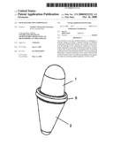
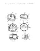
[0012]FIG. 1 shows a general view of the package, the first variant of execution;
[0013]FIG. 2--the same as per FIG. 1, with a partial section;
[0014]FIG. 3--the package as per FIG. 1, view from above;
[0015]FIG. 4--section A-A as per FIG. 3;
[0016]FIG. 5--section B-B as per FIG. 3;
[0017]FIG. 6--unit I as per FIG. 4;
[0018]FIG. 7--unit II as per FIG. 5;
[0019]FIG. 8--unit III as per FIG. 3;
[0020]FIG. 9--shows a general view of the package, the second variant of execution;
[0021]FIG. 10--the same as per FIG. 9, with section;
[0022]FIG. 11--cross-section as per FIG. 9 at the place of location of the protective cleat;
[0023]FIG. 12--cross-section as per FIG. 9, outside the place of location of the protective cleat;
[0024]FIG. 13--unit IY as per FIG. 12;
[0025]FIG. 14--unit Y as per FIG. 11;
[0026]FIG. 15--general view of the connecting cap;
[0027]FIG. 16--the same as per FIG. 15, view from above;
[0028]FIG. 17--section C-C as per FIG. 16;
[0029]FIG. 18--section D-D as per FIG. 16;
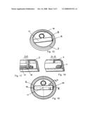
[0030]FIG. 19--shows a general view of the package, the third variant of execution;
[0031]FIG. 20--cross-section as per FIG. 19 on the protective cleat and connective band;
[0032]FIG. 21--cross-section as per FIG. 19 on lugs of the connective band;
[0033]FIG. 22--unit YI as per FIG. 20;
[0034]FIG. 23--unit YII as per FIG. 21;
[0035]FIG. 24--general view of the connecting cap;
[0036]FIG. 25--the same as per FIG. 24, view from above;
[0037]FIG. 26--section E-E as per FIG. 25;
[0038]FIG. 27--general view of the connective band;
[0039]FIG. 28--the same as per FIG. 26, view from above;
[0040]FIG. 29--section G-G as per FIG. 28.
EMBODIMENT OF INVENTION
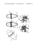
[0041]The package for two components as per the first variant contains two vessels 1 and 2 (FIG. 1-4) connected with each other with external surfaces of necks 3 and 4 (FIG. 6, 7). The package has a connecting cap 5 and membranes 6 and 7 tightly closing each vessel of the package. The neck 3 of the vessel 1 has a lug 8 on the external surface for installation of a connecting cap 5 into it and lugs 9 limiting the turning of this vessel relative to the connecting cap 5. The cap 5 is made with lugs 10 on the internal surface (FIG. 8). The neck 4 of the vessel 2 is made with lugs 11 on the external surface to ensure turning of the connecting cap. The shape of a membrane 6 and 7 of each vessel is like a glass with a closed end part 12 placed inside the vessel and having a side wall made with edges 13 bent outwards and bearing on the end surface 14 of the neck of the corresponding vessel and at the same time the membrane 6 rests against the end part of the membrane 7 with the same edges 13. The connecting cap 5 provides a counter-connection of two necks of the vessels 1 and 2 in such a way that the membrane 6 rests against the membrane 7 around the periphery ensuring a reliable tightness of the vessels (FIG. 6, 7).
[0042]By assembling of the package, the vessel 1 is installed into the connecting cap 5 and fixed inside this at the expense of lugs 8 going under the internal surface of the cap. Then the vessel 1 and the cap 5 are turned upon the vessel 2.
[0043]The above mentioned design of the package ensures a reliable tight packing of different components thanks to the pressing of membranes to the walls and crimp seals of the necks by mutual resting. At that, a possibility of reuse of vessels is provided, as it is possible to remove the membrane out of the vessel and then install it back easily each time for filling or emptying of each vessel.
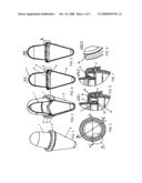
[0044]The package for two components as per the second variant contains two vessels 1 and 2 (FIG. 9-12), connected with each other with external surfaces of necks 3 and 4, the vessels 1 and 2 have technological lugs 15 and 16. The package has a connecting cap 5 and membranes 6 and 7 tightly closing each vessel of the package. The neck 3 of the vessel 1 has a lug 8 on the external surface for installation of a connecting cap 5 into it and lugs 9 limiting the turning of this vessel relative to the connecting cap 5 (FIG. 13, 14). The cap 5 is made with lugs 10 on the internal surface between which the protective cleat 17 with the ring 18 is diametrically located (FIG. 15-18). The cleat 17 has two grooves 19 for convenient removal of this from the cap 5. The cleat 17 presses the edges 13 of the membrane 6 to the end of the surface 14 of the neck of the vessel 1. The neck 4 of the vessel 2 is made with lugs 11 on the external surface to ensure turning of the connecting cap. The shape of a membrane 6 and 7 of each vessel is like a glass with a closed end part 12 directed to inside of the corresponding vessel and other open counter part made with edges 13 bent outwards and bearing on the end surface 14 of the neck of the corresponding vessel and at the same time the membrane 6 rests against the cleat 17 of the membrane 7.
[0045]The connecting cap 5 provides a counter-connection of two necks of the vessels 1 and 2 in such a way that the membrane 6 rests against the protective cleat 17 which rests against the membrane 7 ensuring a reliable tightness of the vessels.
[0046]By opening of the package, the vessel 1 with the cap 5 is separated from the vessel 2. The protective cleat 17 is removed from the cap 5 by means of its separation on grooves 19 giving access to the edges 13 of the membrane 6.
[0047]By assembling of the package, the vessel 1 is installed into the connecting cap 5 and fixed inside this at the expense of lugs 8 going under the internal surface of the cap. Then the vessel 1 and the cap 5 are turned upon the vessel 2.
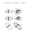
[0048]The package for two components as per the third variant (FIG. 19-29) contains two vessels 1 and 2 connected with each other with the necks 3 and 4 through the connecting cap 5 and connective band 20; membranes 7 and 8 tightly close each vessel.
[0049]The shape of a membrane 6 and 7 of each vessel is like a glass with a closed end part 12 placed inside of the vessel and having a side wall made with edges 13 bent outwards and bearing on the end surface 14 of the neck of the corresponding vessel and at the same time the membrane 6 rests against the end part of the membrane 7.
[0050]The neck 3 has the lugs 8 and 15 on the external surface for installation of the vessel into the connecting cap 5 and the lugs 9 to be installed into the grooves 10 of the cap 5 for limitation of the turning of the vessel relative to the connecting cap 5. The protective cleat 17 having two grooves 16 and a ring 18 is located between the groves 10 on the internal surface of the connecting cap for convenient removal of the protective cleat out of the connecting cap. The cap 5 has the lugs 21 for its connection with the band 20.
[0051]The neck 4 of the vessel 2 has the lugs 16 on the external surface for installation of the vessel into the connective band 20 and the lugs to be installed into the grooves 22 of the connective band 20 limiting the turning of the vessel 2 relative to the band 20. A safety element in form of a U-shaped cleat 23 with two grooves 24 and a ring 23 goes diametrically between the grooves 22 on the internal surface of the band 20 for convenient removal of the safety element 23 out of the band 20. The lugs 26 are made on the external surface of the band 20 to ensure turning of the connecting cap.
[0052]The membranes 7 and 8 of each vessel have a cylindrical shape with the closed end part directed into the corresponding vessel and other open counter part made from the neck of the corresponding vessel.
[0053]The connecting cap 5 and the band 20 provide a counter-connection of two necks of the vessels 1 and 2 in such a way that the membrane 7 rests with its edge 13 against the protective cleat 17 which rests against a safety element--the cleat 23 pressing the edge 13 of the membrane 8 to the end of the surface 14 of the neck of the vessel 2 ensuring a reliable tightness of the vessels.
[0054]By assembling of the package, the vessel 1 is closed with the membrane 7 and installed into the grooves 10 of the cap 5; the vessel 2 is closed with the membrane 8 and installed into the grooves 22 of the band 20. Then the vessel 1 and the cap 5 are turned upon the band 20 of the vessel 2.
[0055]By disassembling of the package, the vessel 1 with the cap 5 is turned off from the band 20 of the vessel 2. By pulling the ring 18 there is possible to open the cleat 17 from the cap 5 and have access to opening of the membrane 7 of the vessel 1. By pulling the ring 25 of the band 20 there is possible to open the safety element 23 and have access to opening of the membrane 8 of the vessel 2.
[0056]The vessels 1 and 2 can be made of PET performs or other materials, e.g., glass, having a rigid neck. The PET performs can be blown to any vessel of various configurations.
[0057]This utility model allows to solve a problem of the tight packing of different components in two isolated vessels in one package. At that, the convenience, ease and simplicity of both disassembling of vessels in the package and packing of them in this package are provided.
INDUSTRIAL APPLICABILITY
[0058]This invention is industrially applicable, as it can be made of polymeric materials of type of PET with use of blowing methods, as by manufacturing of polymeric vessels for water, soft drinks etc.
User Contributions:
comments("1"); ?> comment_form("1"); ?>Inventors list |
Agents list |
Assignees list |
List by place |
Classification tree browser |
Top 100 Inventors |
Top 100 Agents |
Top 100 Assignees |
Usenet FAQ Index |
Documents |
Other FAQs |
User Contributions:
Comment about this patent or add new information about this topic:
| People who visited this patent also read: | |
| Patent application number | Title |
|---|---|
| 20130214826 | FULLY DIGITAL METHOD FOR GENERATING SUB CLOCK DIVISION AND CLOCK WAVES |
| 20130214825 | DRIVE UNIT FOR DRIVING VOLTAGE-DRIVEN ELEMENT |
| 20130214824 | DRIVING CIRCUIT |
| 20130214823 | GATE DRIVING CIRCUIT |
| 20130214822 | GATE DRIVE CIRCUIT |
Images included with this patent application:
 |  |
 |  |
 |  |
| Similar patent applications: | |
| Date | Title |
|---|---|
| 2008-11-20 | Package set for piece mass consumption goods |
| 2012-09-20 | Support arrangement for an inner component |
| 2010-11-25 | Flip open package with tiered compartments |
| 2012-06-21 | Packaging device for cosmetic products |
| 2012-06-28 | Flip open stadium package for consumable products |
| New patent applications in this class: | |
| Date | Title |
|---|---|
| 2016-06-23 | Deformation-resistant container with panel indentations |
| 2016-06-16 | Drinking vessel with ergonomic rim |
| 2016-05-05 | Formatting container |
| 2016-04-28 | Transport holder for an object to be transported and method for transporting an object to be transported using said type of transport holder |
| 2016-02-11 | Body engaging concave container |
| New patent applications from these inventors: | |
| Date | Title |
|---|---|
| 2013-10-31 | Rattle-tumber toy |
| Top Inventors for class "Receptacles" | |
| Rank | Inventor's name |
|---|---|
| 1 | Daniel Lee Bizzell |
| 2 | Frank Yang |
| 3 | Terry Vovan |
| 4 | William P. Apps |
| 5 | Lowell L. Wood, Jr. |