Patent application title: CLEANING MEMBER
Inventors:
Gouki Sasagawa (Shinagawa-Ku, JP)
Takanori Hara (Shinagawa-Ku, JP)
Assignees:
SYNZTEC CO., LTD
IPC8 Class: AA47L1340FI
USPC Class:
15 151
Class name: Brushing, scrubbing, and general cleaning electrostatic cleaning
Publication date: 2008-10-16
Patent application number: 20080250582
Inventors list |
Agents list |
Assignees list |
List by place |
Classification tree browser |
Top 100 Inventors |
Top 100 Agents |
Top 100 Assignees |
Usenet FAQ Index |
Documents |
Other FAQs |
Patent application title: CLEANING MEMBER
Inventors:
Gouki Sasagawa
Takanori Hara
Agents:
SUGHRUE MION, PLLC
Assignees:
SYNZTEC CO., LTD.
Origin: WASHINGTON, DC US
IPC8 Class: AA47L1340FI
USPC Class:
15 151
Abstract:
The present invention provides a cleaning member which can be produced at
low cost and which maintains excellent cleaning performance for a long
period of time. The cleaning member includes a core member, a lower layer
formed through winding a cord member around the core member at the
surface thereof, and an upper layer provided on the outer surface of the
lower layer. The upper layer is formed of at least one fiber layer made
of woven fabric or knitted fabric.Claims:
1. A cleaning member comprising:a core member,a lower layer formed through
winding a cord member around the core member at the surface thereof,
andan upper layer provided on the outer surface of the lower layer,
wherein the upper layer is formed of at least one fiber layer made of
woven fabric or knitted fabric.
2. A cleaning member as described in claim 1, wherein the cord member is made of spun yarn.
3. A cleaning member as described in claim 1, wherein the cord member is made of a thermoplastic elastomer.
4. A cleaning member as described in claim 1, wherein the cord member has a diameter of 0.5 to 3.0 mm.
5. A cleaning member as described in claim 1, wherein the upper layer is formed of a plurality of fiber layers, whose materials are identical to or different from one another.
6. A cleaning member as described in claim 1, wherein the upper layer is formed of a plurality of fiber layers, whose fabric types are identical to or different from one another.
7. A cleaning member as described in claim 1, which has a roller shape.
Description:
[0001]The entire disclosure of Japanese Patent Applications Nos.
2007-105255 filed on Apr. 12, 2007 and 2008-101859 filed on Apr. 9, 2008
is expressly incorporated by reference herein.
BACKGROUND OF THE INVENTION
[0002]1. Field of the Invention
[0003]The present invention relates to a cleaning member for removing toner, additives, paper dust, etc. and more particularly to a cleaning member suitable for a cleaning roller for removing toner deposited on a charge-imparting roller and a photoreceptor employed in a copying machine, a printer, a facsimile, etc.
[0004]2. Background Art
[0005]Image-forming machines; for example, copying machines, printers, and complex office-automation (OA) machines having copying and printing functions, employ a cleaning blade or a cleaning roller. The cleaning roller removes toner, additives, paper dust, and other foreign matter deposited on a charge-imparting roller and a photoreceptor, through contact therewith. When the cleaning roller cannot sufficiently remove such foreign matter, members such as a charge-imparting roller and a photoreceptor are damaged, resulting in printed-image failures. Therefore, the cleaning roller is required to maintain its cleaning performance for a long period of time.
[0006]Japanese Patent No. 2847524 discloses a charge-imparting apparatus employing a cleaning member formed of sponge material, and Japanese Patent Application Laid-open (kokai) No. 2006-064774 discloses a toner-supplying roller including a cylindrical elastic member and a fiber layer formed of entangled melt-adhesive fiber.
[0007]In Japanese Patent No. 2847524, a hole is provided in a block of molded foam, and a core member is inserted in the hole. In Japanese Patent Application Laid-Open (kokai) No. 2006-064774, a molded roller is covered with melt-adhesive fiber, and the fiber-coated roller is heated again by use of a mold. These processes require a number of production steps, elevating production cost. In addition, since these rollers do not successfully hold removed foreign matter, the rollers cannot be used for a prolonged period of time.
SUMMARY OF THE INVENTION
[0008]In view of the foregoing, an object of the present invention is to provide a cleaning member which can be produced at low cost and which maintains excellent cleaning performance for a long period of time.
[0009]In a first mode of the present invention for attaining the object, there is provided a cleaning member comprising:
[0010]a core member,
[0011]a lower layer formed through winding a cord member around the core member at the surface thereof, and
[0012]an upper layer provided on the outer surface of the lower layer, wherein the upper layer is formed of at least one fiber layer made of woven fabric or knitted fabric.
[0013]A second mode of the invention is drawn to a specific embodiment of the cleaning member of the first mode, wherein the cord member is made of spun yarn.
[0014]A third mode of the invention is drawn to a specific embodiment of the cleaning member of the first mode, wherein the cord member is made of a thermoplastic elastomer.
[0015]A fourth mode of the invention is drawn to a specific embodiment of the cleaning member of any of the first to third modes, wherein the cord member has a diameter of 0.5 to 3.0 mm.
[0016]A fifth mode of the invention is drawn to a specific embodiment of the cleaning member of any of the first to fourth modes, wherein the upper layer is formed of a plurality of fiber layers, whose materials or fabric types (i.e., woven and knitted) are identical to or different from one another.
[0017]A sixth mode of the invention is drawn to a specific embodiment of the cleaning member of any of the first to fifth modes, wherein the cleaning member has a roller shape.
[0018]The present invention realizes provision of a cleaning member which can be produced at low cost and which maintains excellent cleaning performance for a long period of time.
BRIEF DESCRIPTION OF THE DRAWINGS
[0019]Various other objects, features, and many of the attendant advantages of the present invention will be readily appreciated as the same becomes better understood with reference to the following detailed description of the preferred embodiments when considered in connection with the accompanying drawings, in which:
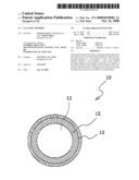
[0020]FIGS. 1A and 1B are sketches of a cleaning roller, which is an embodiment of the cleaning member of the present invention;
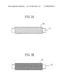
[0021]FIGS. 2A and 2D are sketches for illustrating the method of producing the cleaning roller shown in FIGS. 1A and 1B; and
[0022]FIGS. 3A and 3B are schematic enlarged views of a portion of the upper layer of a cleaning roller.
DETAILED DESCRIPTION OF PREFERRED EMBODIMENTS
[0023]The cleaning member according to the present invention includes a core member, a lower layer formed through winding a cord member around the core member at the surface thereof, and an upper layer provided on the outer surface of the lower layer. By virtue of the lower layer and the upper layer, toner, additives, paper dust, and other foreign matter deposited on a member can be suitably removed through contact therewith, and such a good performance is maintained for a long period of time.
[0024]Hereinafter, taking a cleaning roller as an example of the cleaning member of the present invention, the present invention will be described in detail.
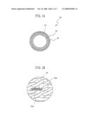
[0025]FIGS. 1A and 1B are sketches of a cleaning roller, which is an embodiment of the cleaning member of the present invention. FIG. 1A is a cross-section of the cleaning member, and FIG. 11 is a schematic enlarged view of a portion of the upper layer of the cleaning member.
[0026]As shown in FIG. 1A, a cleaning roller 10 has a lower layer 12 formed through winding a cord member around a core member 11 at the surface thereof, and an upper layer 13 provided on the outer surface of the lower layer 12.
[0027]Referring to FIGS. 2A and 2B, the method for producing the cleaning roller 10 shown in FIGS. 1A and 1B will be briefly described. Firstly, an adhesive is applied to wool-like spun yarn, which is an example of the cord member. As shown in FIG. 2A, the cord member is spirally wound around the core member 11, so that the entire surface of the member 11 is covered therewith, to thereby form the lower layer 12. As shown in FIG. 2B, knitted fabric is attached and adhered to the lower layer 12, to thereby form the upper layer 13 on the lower layer 12, whereby the cleaning roller 10 is produced. As used herein, the term "wool-like spun yarn" refers to spun yarn having a morphological property corresponding to wool-like compressibility and resilience.
[0028]The lower layer 12 replaces an elastic layer of a conventional cleaning member. When the upper layer 13 comes to be in contact with a contact member, the lower layer 12 is deformed together with the upper layer 13 in response to the surface shape of the contact member. In other words, since the lower layer 12 absorbs deformation of the upper layer 13, the surface of the cleaning roller 10 comes into close contact with the contact member. Then, when the upper layer 13 parts from the contact member, the pressure applied to the lower layer 12 is released, and the shape of the roller 10 is returned to the initial shape through resilience of the lower layer 12. As compared with a conventional cleaning member, the cleaning roller 10 having the lower layer 12 can be produced in a simple manner at low cost.
[0029]The lower layer 12 is suitable for holding toner, additives, paper dust, and other foreign matter deposited on the upper layer 13 provided on the lower layer 12. Since the wool-like spun yarn which serves as the lower layer 12 of this embodiment has a rough surface having protrusions and dented portions, toner and other foreign matter deposited in the upper layer 13 fall into the dented portions and are held therein. In addition, because the lower layer 12 is formed through winding wool-like spun yarn around the core member, toner and other foreign matter also fall into interspace between spun yarn filaments. Thus, a large amount of toner and the like can be held by the cleaning member. Therefore, the cleaning member of this embodiment can maintain excellent cleaning performance for a long period of time.
[0030]In the present embodiment, the lower layer 12 is produced through winding wool-like spun yarn around the surface of the core member 11. However, the production method is not limited thereto. For example, another type of cord member may be wound around the surface of the core member 11, to thereby form the lower layer 12. Although no particular limitation is imposed on the cord member, the member per se preferably has a predetermined compressibility and resilience. Alternatively, even when the cord member per se does not have a predetermined compressibility or resilience, the cord member is wound in a specific manner so as to attain a predetermined compressibility and resilience, to thereby form the lower layer 12. The compressibility may be of such a value that, when the upper layer 13 comes into contact with a contact member, the lower layer 12 is deformed with the upper layer 13 in response to the surface shape of the contact member.
[0031]The cord member which serves as the lower layer 12 preferably has a diameter of 0.5 to 3.0 mm. When the diameter falls within the range, a thickness, a compressibility, and a resilience of interest can be attained. When a cord member having a diameter of more than 3.0 mm is employed, a satisfactory cleaning effect can be attained. However, since a cleaning roller produced therefrom has a large roller diameter, such a cleaning roller is not suited for the purpose of downsizing a complex OA machine. Needless to say, one or more species of cord members having a diameter of less than 0.5 mm may be wound twice or more around a core member, so as to attain a thickness, a compressibility, and a resilience of interest.
[0032]Examples of the cord member include a variety of yarns and threads and elastomer cords. The term "elastomer cord" refers to an extruded cord-shape product of an elastomer.
[0033]Examples of the yarn and thread include spun yarn such as wool, filament thread, long-short complex fiber obtained through combining filament thread and spun yarn, and bulky fiber obtained through processing multi-filament threads. These yarns and threads preferably have an apparent density of 0.2 to 0.6 g/cm3. When the apparent density is excessively low, the lower layer 12 encounters difficulty in maintaining the roller shape. The apparent density refers to a value calculated by dividing the weight of fiber having a large number of pores by bulk volume obtained from apparent fiber thickness. No particular limitation is imposed on the material of the yarn and thread, and examples of the material include polyester, nylon, acrylic material, rayon, and wool.
[0034]The elastomer cord preferably has a hardness (JIS A) of 80° or less and a permanent compressive strain of 30% or less, in order to ensure satisfactory deformation and facilitate resilience; i.e., to produce a lower layer 12 having good resilience. Specific examples of the material of the elastomer cord include styrenic elastomer and olefinic elastomer.
[0035]As shown in FIG. 1B, the upper layer 13 of the present embodiment is formed of knitted fabric produced through knitting yarns 13A obtained through twisting fiber filaments 13a. The fiber filament 13a has a diameter of 5 μm to 100 μm and an aspect ratio (length/diameter) of 100 or more. In the present embodiment, yarn 13A is produced through twisting fiber filaments 13a.
[0036]The yarn 13A has a very small diameter, differing from the cord member which serves as the lower layer 12. For example, the diameter (apparent thickness) is preferably 80 to 500 μm, for the following reasons. Since the particle size of the toner deposited on a contact member is, for example, 5 to 10 μm, such a thin yarn is suitable for scraping the toner of such a particle size. Also, space 14 provided by knitted yarn 13A having such a diameter effectively scrapes and captures toner and other foreign matter. In addition, such a diameter enables the yarn to have sufficient strength for cleaning. When the yarn has an apparent thickness less than 80 μm, mechanical strength may decrease, whereas when the apparent thickness is in excess of 500 μm, softness of the upper layer 13 may be impaired, resulting in a drop in cleaning performance. Needless to say, both cases are not preferred.
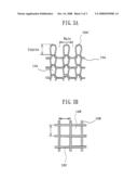
[0037]In the aforementioned knitted fabric, the course width (μm) and the wale width (μm) are preferably 3 to 10 times the apparent thickness (μm) of the yarn 13A, particularly preferably 3 to 7 times. The apparent fiber thickness is not a diameter index (weight per unit fiber length) represented by d (denier) or dTex (deci-Tex), but an actual fiber thickness measured under a microscope or the like.
[0038]As shown in FIG. 3A, the course refers to a row of loops 13A' in the lateral direction (lateral row), and the wale refers to a row of loops 13A' in the longitudinal direction (longitudinal row). The course width is a width of a lateral row; i.e., the distance between tops of the loops 13A', and the wale width is a width of a longitudinal row; i.e., the pitch of loops 13A'. When the knitted fabric has a course width and a wale width which are 3 to 10 times the apparent thickness of the yarn, the yarns 13A are not completely fixed but can move freely in the lateral and longitudinal directions. In this state, the yarns 13A can follow deformation. Thus, toner, paper dust, and other foreign matter deposited on a contact member can be readily scraped off through contact with the knitted fabric. Also, knitted fabric having a course width and a wale width which are 3 to 10 times the apparent thickness of the yarn provides relatively large spaces 14A. The scraped matter is received in the spaces 14A and readily falls through the spaces 14A into the inside of the upper layer 13. Thus, the scraped matter can be held in the lower layer 12 in a large amount. Therefore, the cleaning roller 10 can maintain the cleaning performance for a long period of time. Notably, knitted fabric having a course width and/or a wale width which are less than 3 times the apparent thickness of the yarn does not follow deformation of the yarn 13A and encounters difficulty in holding the scraped matter, whereas knitted fabric having a course width and/or a wale width which are more than 10 times the apparent thickness of the yarn follows deformation of the yarn to an improved extent, but has a decreased contact area with respect to a contact member, possibly lowering the cleaning performance.
[0039]No particular limitation is imposed on the knitting type of the knitted fabric, and example of the knitting type include plain stitch, rib stitch, tuck stitch, float stitch, half cardigan, interlock stitch, lace stitch, and pile stitch.
[0040]The cleaning roller of the present embodiment scrapes toner and other foreign matter deposited on a contact member through movement of the yarns 13A in a direction of rotation of the roller, to thereby clean the contact member. Specifically, toner and other foreign matter are captured by at least a first portion of fiber filaments 13a forming the yarn 13A, and a second portion of the filaments 13a sustains the first portion, while the cleaning roller 10 rotates. Thus, the toner and other foreign matter deposited on the contact member are scraped off, and the scraped matter falls in the spaces 14 provided by the yarns 13A. As mentioned above, the scraped toner and other foreign matter further fall into the lower layer 12, where they are held. Thus, knitted fabric produced through knitting yarns 13A obtained through twisting fiber filaments 13a can successfully remove toner, additives, paper dust, and other foreign matter.
[0041]In the present embodiment, the upper layer 13 is formed from knitted fabric. Alternatively, the layer may be formed from woven fabric. Examples of the woven fabric include three essential structures (e.g., plain weave, twill weave, and satin weave) and combination weave.
[0042]Preferably, the woven fabric has an interwarp distance (μm) which is 3 to 10 times the apparent thickness (μm) of the warp, and an interweft distance (μm) which is 3 to 10 times the apparent thickness (μm) of the weft. Particularly preferably, the distances are 3 to 7 times the apparent thickness. As shown in FIG. 3B, the distance between the warps 13B and the distance between the wefts 13C are the distance between width-direction centers of the yarns adjacent to each other. When the woven fabric has a distance (μm) between the warps 13B which is 3 to 10 times the apparent thickness (μm) of the warp 13B, and a distance (μm) between the wefts 13C which is 3 to 10 times the apparent thickness (μm) of the weft 13C, the warps 13B and wefts 13C are not completely fixed but can move freely in the lateral and longitudinal directions, and relatively large spaces 14B are provided. Therefore, the effects as mentioned in relation to the above embodiment can also be attained. Notably, woven fabric having a distance (μm) between the warps 13B which is less than 3 times the apparent thickness (μm) of the warp 13B or a distance (μm) between the wefts 13C which is less than 3 times the apparent thickness (μm) of the weft 13C does not follow deformation of the warp 13B or weft 13C and encounters difficulty in holding the scraped matter, whereas woven fabric having a distance (μm) between the warps 13C which is more than 10 times the apparent thickness (μm) of the warp 13B or a distance (μm) between the wefts 13C which is more than 10 times the apparent thickness (μm) of the weft 13C follows deformation of the warp 13B or weft 13C to an improved extent, but has a decreased contact area with respect to a contact member, possibly lowering the cleaning performance.
[0043]No particular limitation is imposed on the apparent thickness of the warps and wefts forming the woven fabric. In the woven fabric, the warp and the weft may be formed from different materials and may have different apparent thicknesses.
[0044]The yarn (knitted fabric), warp, and weft (woven fabric) forming the upper layer 13 are a bundle of fiber filaments. Needless to say, twisted yarn and knitted yarn may also be employed. So long as the cleaning performance is not impaired, fiber filaments including fancy fiber filaments may be bundled. The fiber filaments forming the yarn (knitted fabric), warp, and weft (woven fabric) preferably have a diameter of 5 to 100 μm. When the filament diameter is less than 5 μm, fiber strength is insufficient, whereas when the filament diameter is in excess of 100 μm, softness of the upper layer 13 may be impaired, resulting in a drop in cleaning performance.
[0045]So long as the cleaning performance is not impaired, the knitted fabric or the woven fabric may further include other types of fiber filaments, in addition to the yarn, warp, or weft satisfying the aforementioned conditions. Examples include a curly fiber filament which has a diameter smaller than that of the yarn, warp, or weft, or a raised fiber filament.
[0046]No particular limitation is imposed on the material of the yarn (knitted fabric), warp, and weft (woven fabric), and examples of the material include cotton, wool, hemp, silk, polyester, nylon, and acrylic material. Of these, polyester, nylon, and acrylic material are preferred, from the viewpoints of durability and cost.
[0047]The upper layer 13 preferably has an apparent thickness of 0.5 mm or more, since excellent mechanical properties including mechanical strength and wear resistance can be attained.
[0048]So long as toner and other foreign matter can be effectively removed, the upper layer 13 may be formed of a plurality of layers in which a woven fabric layer or a knitted fabric layer are stacked. For producing the upper layer 13 having a multi-layer structure, a woven fabric layer and a knitted fabric layer may be stacked. Alternatively, woven fabric layers may be stacked, or knitted fabric layers may be stacked. In the case of stacking woven fabric layers, woven fabric layers made of different materials may be stacked, or those made of the same material may also be stacked.
[0049]The upper layer 13 is not limited to the aforementioned structures, and may be formed of pile-weave woven fabric. The pile-weave woven fabric refers to woven fabric made from base yarn with warp or weft for forming piles such that piles (uncut or cut) are incorporated into a surface of the woven fabric.
[0050]The upper layer formed of pile-weave fabric preferably has a thickness of 0.5 to 3.0 mm. When the thickness is less than 0.5 mm, deformation of the roller surface is insufficient, whereas when the thickness is more than 3.0 mm, a satisfactory cleaning effect can be attained. However, since a cleaning roller produced therefrom has a large roller diameter, such a cleaning roller is not suited for the purpose of down-sizing a complex CA machine.
[0051]The single filament of the pile-weave fabric preferably has a diameter of 5 to 500 dTex, in order to attain strength sufficient for cleaning. When the single filament has a diameter less than 5 dTex, mechanical strength may be poor, whereas when the diameter exceeds 500 dTex, softness of the upper layer 13 is reduced, possibly damaging the contact member. Both cases are not preferred.
[0052]The pile-weave fabric preferably has a filament density of 6,400 to 46,000 filaments/cm2. When the filament density falls within this range, the upper layer 13 can sufficiently hold foreign matter.
[0053]No particular limitation is imposed on the material of single filaments forming the pile-weave fabric, and examples of the material include polyamide, polyester, acrylic material, and polyolefin.
[0054]When the cleaning roller 10 of the present embodiment is employed, toner and other foreign matter deposited on a contact member are scraped off by means of the upper layer 13. The toner and other foreign matter deposited on the upper layer 13 fall into the lower layer 12, where they are held. The thus-held matter does not return to the upper layer 13. Therefore, the cleaning roller 10 of the present embodiment effectively removes toner and other foreign matter on the contact member for a long period of time.
[0055]If the cleaning performance of the cleaning roller 10 of the present embodiment is lowered as a result of use over a long period of time, the lower layer 12 is removed from the core member 11. Since the lower layer 12 can be readily removed, the core member 11 can be reused. Through reuse of the core member 11 removed from the cleaning roller 10, another cleaning roller 10 can be produced at lower cost.
[0056]The cleaning member of the present invention is suitable for a cleaning roller, particularly for a cleaning roller for removing toner deposited on a charge-imparting roller and a photoreceptor employed in copying machines, printers, facsimiles, etc.
EXAMPLES
[0057]The present invention will next be described in detail by way of examples, which should not be construed as limiting the invention thereto.
Example 1
[0058]An adhesive (Saivinol HM-680, product of Saiden Chemical Industry Co., Ltd.) was applied onto wool-like yarn (acrylic fiber) (diameter: 1.5 mm), and the yarn was wound around a core member (φ: 6.0 mm), to thereby form a lower layer on the core member. Subsequently, the lower layer was covered with knitted fabric made of 6-nylon (apparent fiber thickness; 250 μm, course width: about 900 μm, wale width: about 1,100 μm, and apparent thickness: 600 μm), and the fabric was adhered to the lower layer. The thus-formed roller was cut to pieces having a predetermined length, to thereby produce cleaning rollers of Example 1.
Example 2
[0059]The procedure of Example 1 was repeated, except that belt-form knitted fabric made of rayon (apparent fiber thickness: 80 μm, interwarp distance; about 500 μm, interweft distance: about 600 μm, and apparent thickness; 500 μm) was wound instead of knitted fabric, to thereby produce cleaning rollers of Example 2.
Example 3
[0060]The procedure of Example 1 was repeated, except that an elastomer cord (diameter; 1.5 mm) formed through molding a thermoplastic elastomer (Septon 4055, product of Kuraray Co., Ltd.) was used instead of wool-like yarn, to thereby produce cleaning rollers of Example 3.
Example 4
[0061]An adhesive (Saivinol HM-680, product of Saiden Chemical Industry Co., Ltd.) was applied onto wool-like yarn (acrylic fiber) (diameter: 1.5 mm), and the yarn was wound around a core member (φ: 6.0 mm). The wool-like yarn was further wound around the surface of the adhesive-coated yarn, to thereby form a lower layer. Subsequently, the lower layer was covered with knitted fabric made of 6-nylon (apparent fiber thickness: 250 μm, course width; about 900 μm, wale width; about 1,100 μm, and apparent thickness: 600 μm), and the fabric was adhered to the lower layer. The thus-formed roller was cut to pieces having a predetermined length, to thereby produce cleaning rollers of Example 4.
Example 5
[0062]An adhesive (Saivinol HM-680, product of Saiden Chemical Industry Co., Ltd.) was applied onto wool-like yarn (acrylic fiber) (diameter: 1.5 mm), and the yarn was wound around a core member (φ: 6.0 mm). Subsequently, the adhesive-coated yarn was covered with knitted fabric made of 6-nylon (apparent fiber thickness: 350 μm, course width: about 800 μm, wale width; about 900 μm, and apparent thickness: 800 μm), and the fabric was adhered. The fabric was further covered with knitted fabric made of 6-nylon (apparent fiber thickness: 250 μm, course width: about 900 μm, wale width: about 1,100 μm, and apparent thickness: 600 μm), and the fabric was adhered thereto. The thus-formed roller was cut to pieces having a predetermined length, to thereby produce cleaning rollers of Example 5.
Example 6
[0063]The procedure of Example 1 was repeated, except that pile-weave fabric made of nylon single filaments (diameter: 110 dTex) (density: 33,000 filaments/cm2, thickness; 1.9 mm) was used instead of knitted fabric, to thereby produce cleaning rollers of Example 6.
Example 7
[0064]The procedure of Example 1 was repeated, except that pile-weave fabric made of nylon single filaments (diameter: 110 dTex) (density: 27,000 filaments/cm2, thickness: 1.8 mm) was used instead of knitted fabric, to thereby produce cleaning rollers of Example 7.
Example 8
[0065]The procedure of Example 1 was repeated, except that pile-weave fabric made of acetate single filaments (diameter: 130 dTex) (density: 19,800 filaments/cm2, thickness: 1.9 mm) was used instead of knitted fabric, to thereby produce cleaning rollers of Example 8.
Example 9
[0066]The procedure of Example 1 was repeated, except that pile-weave fabric made of ester single filaments (diameter; 84/2 dTex; i.e., 84-dTex single filament was divided into two) (density: 34,000 filaments/cm2, thickness: 1.9 mm) was used instead of knitted fabric, to thereby produce cleaning rollers of Example 9.
Comparative Example 1
[0067]A melamine resin foam piece (product of BASF) was sliced into rectangular pieces. A hole for receiving a core member was provided in one rectangular piece. A core member onto which an adhesive had been applied was inserted to the hole, followed by melt-adhering. Subsequently, the surface of the rectangular piece was polished to a roller shape, and the thus-formed roller was cut to pieces having a predetermined length, to thereby produce cleaning rollers of Comparative Example 1.
[0068]Steps for producing cleaning rollers of Examples 1 to 3, Examples 6 to 9, and Comparative Example 1 are shown in Table 1.
TABLE-US-00001 TABLE 1 Examples Examples Comparative Step 1 and 2 Example 3 6 to 9 Example 1 1 Application of Application of adhesive to Application of Production of adhesive to wool- elastomer adhesive to wool- polymer foam like yarn like yarn 2 Winding wool-like Winding elastomer around Winding wool-like Slicing yarn around core core member yarn around core member member 3 Affixing knitted Affixing knitted fabric Affixing woven Hole making fabric fabric 4 Cutting Cutting Cutting Application of adhesive to core member 5 -- -- -- Surface polishing 6 -- -- -- Cutting
[0069]As shown in Table 1, the cleaning rollers of Examples 1 to 3 and of Examples 6 to 9 were produced through a smaller number of steps as compared with the cleaning rollers of Comparative Example 1. Also, the cleaning rollers of the Examples were produced from a low-cost material. Thus, the cleaning roller according to the present invention can be produced through a smaller number of steps and at low cost.
Test Example 1
[0070]Each of the cleaning rollers of the Examples and Comparative Example 1 was caused to come into contact with a charge-imparting roller which was in contact with a photoreceptor, at a pressure so as to adjust the deformation of the cleaning roller to 0.1 mm. Thereafter, a toner (about 0.03 g) was uniformly applied onto an area (width: 100 mm) of the charge-imparting roller. The photoreceptor was rotated at 300 rpm by means of a driving motor. In this case, the charge-imparting roller and the cleaning roller rotate to follow the rotation of the photoreceptor.
[0071]After operation of the driving motor for 15 minutes, the surface of the charge-imparting roller was observed. When the surface of the charge-imparting roller had been successfully cleaned, the same operation was repeated. In the case where no cleaning effect on the charge-imparting roller was observed, repetition of the operation was stopped. The results are shown in Table 2.
<Type of Toner>
[0072]Digital toner (product of Konica Minolta), including styrene resin (6 μm), silicone additive, and titanium oxide (0.6 μm)
TABLE-US-00002 TABLE 2 Cleaning operation (times) Example 1 10 Example 2 7 Example 3 10 Example 4 12 Example 5 11 Example 6 ≧20 Example 7 ≧20 Example 8 ≧20 Example 9 ≧20 Comparative 8 Example 1
[0073]As is clear from Table 2, the cleaning members of Examples 1 to 5 exhibit cleaning performance which is at the same or a higher level of performance of the cleaning rollers of Comparative Example 1 (conventional cleaning rollers). The cleaning rollers of Examples 6 to 9 maintain excellent cleaning performance for a longer period of time, as compared with the cleaning rollers of Comparative Example 1.
[0074]As described hereinabove, the cleaning roller according to the present invention can be produced through a small number of steps and at low cost, and maintains excellent cleaning performance for a long period of time.
[0075]When the cleaning member of the present invention is formed into a roller, the roller diameter can be adjusted by modifying the diameter of the cord member forming the lower layer and without any polishing step. Thus, the number of production steps can be reduced, and reduction of production cost and industrial waste can be realized.
User Contributions:
comments("1"); ?> comment_form("1"); ?>Inventors list |
Agents list |
Assignees list |
List by place |
Classification tree browser |
Top 100 Inventors |
Top 100 Agents |
Top 100 Assignees |
Usenet FAQ Index |
Documents |
Other FAQs |
User Contributions:
Comment about this patent or add new information about this topic:
Images included with this patent application:
 |  |
 |  |
 |  |
| Similar patent applications: | |
| Date | Title |
|---|---|
| 2012-10-04 | Starch head having a stiffening member |
| 2012-12-27 | Cleaning system with attachable dispenser |
| 2012-11-22 | Method and apparatus for cleaning consumable drink and food containers |
| 2012-12-27 | Cleaning article comprising melamine foam sponge |
| 2013-01-31 | Robot cleaner and self testing method of the same |
| New patent applications in this class: | |
| Date | Title |
|---|---|
| 2016-06-02 | Vacuum cleaner |
| 2016-03-03 | Dedusting and destaticizing device |
| 2014-09-25 | Cleaning system |
| 2014-09-18 | System for electrostatic removal of debris and associated methods |
| 2014-03-27 | Static eliminating and dust removing apparatus |
| New patent applications from these inventors: | |
| Date | Title |
|---|---|
| 2008-10-16 | Cleaning member |
| Top Inventors for class "Brushing, scrubbing, and general cleaning" | |
| Rank | Inventor's name |
|---|---|
| 1 | Wayne Ernest Conrad |
| 2 | Xavier Boland |
| 3 | Helmut Depondt |
| 4 | Robert Moskovich |
| 5 | James Dyson |