Patent application title: Bifurcate Arbiter
Inventors:
David Brown (Ontario, CA)
IPC8 Class: AH04L1256FI
USPC Class:
370419
Class name: Pathfinding or routing switching a message which includes an address header input or output circuit, per se (i.e., line interface)
Publication date: 2008-09-18
Patent application number: 20080225876
itch comprising a two buffers, a media access
controller having data outputs coupled to the two buffers, and two
control outputs coupled to respective buffers for buffering input data at
a clock rate one-half that of the input data and a switch fabric
connected to the two buffers for matching buffer data throughput with
switch data throughput, the arbiter comprising first and second
schedulers, each scheduler includes a plurality of inputs for connection
to the two buffers for receiving requests, a plurality of outputs for
granting requests and a plurality of inter connections to each of the
plurality of schedulers for informing them of grants and logic for
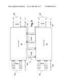
logically grouping input ports associated with a bifurcate input port,
logically grouping output ports associated with a bifurcate output port,
establishing round robin pointers for each of two alternate clock ticks
for tracking next allowable requests and on one clock tick allowing
connection requests from input ports to output ports and accepting a
connection request in dependence upon the grouping of the input and
output ports and the round robin pointer. The arbiter can be generalized
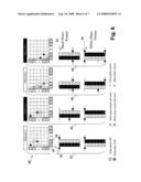
to an n-furcated switch having n-furcated ports where n is an integer
greater than or equal to two.Claims:
1. A method of switching for a space switch having bifurcate ports and
ports, the method comprising the steps of:logically grouping input ports
associated with a bifurcate input port;logically grouping output ports
associated with a bifurcate output port;establishing round robin pointers
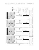
for each of two alternate clock ticks for tracking next allowable
requestson one clock tick allowing connection requests from input ports
to output ports; andaccepting a connection request in dependence upon the
grouping of the input and output ports and the round robin pointer.
2. The method of claim 1 wherein the step of accepting a connection request includes a step of moving the round robin pointer in dependence upon the grouping of the output ports.
3. The method of claim 2 wherein a bifurcate input port connected to a bifurcate output port.
4. The method of claim 2 wherein a single input port connected to a bifurcate output port.
5. The method of claim 2 wherein a bifurcate input port connected to an single output port.
6. An arbiter for a space switch comprising a two buffers, a media access controller having data outputs coupled to the two buffers, and two control outputs coupled to respective buffers for buffering input data at a clock rate one-half that of the input data and a switch fabric connected to the two buffers for matching buffer data throughput with switch data throughput, the arbiter comprising first and second schedulers, each scheduler includes a plurality of inputs for connection to the two buffers for receiving requests, a plurality of outputs for granting requests and a plurality of inter connections to each of the plurality of schedulers for informing them of grants and logic for logically grouping input ports associated with a bifurcate input port, logically grouping output ports associated with a bifurcate output port, for establishing round robin pointers for each of two alternate clock ticks for tracking next allowable requests and for on one clock tick allowing connection requests from input ports to output ports and accepting a connection request in dependence upon the grouping of the input and output ports and the round robin pointer.
7. The arbiter of claim 6 wherein the logic includes means for moving the round robin pointer in dependence upon the grouping of the output ports.
8. The arbiter of claim 7 wherein the logic allows a bifurcate input port to be connected to a bifurcate output port.
9. The arbiter of claim 7 wherein the logic allows a single input port to be connected to a bifurcate output port.
10. The arbiter of claim 7 wherein the logic allows a bifurcate input port to be connected to a single output port.
11. A method of switching for a space switch, the method comprising the steps of:logically grouping input ports associated with a 2.sup.n-furcated input port;logically grouping output ports associated with a 2.sup.n-furcated output port;establishing round robin pointers for each of n clock ticks for tracking next allowable requests;on a clock tick allowing connection requests from input ports to output ports; andaccepting a connection request in dependence upon the grouping of the input and output ports and the round robin pointer.
12. The method of claim 11 wherein the step of accepting a connection request includes a step of moving the round robin pointer in dependence upon the grouping of the output ports.
13. The method of claim 12 wherein a 2.sup.n-furcate input port connected to a 2.sup.n-furcate output port.
14. The method of claim 12 wherein a single input port connected to a 2.sup.n-furcate output port.
15. The method of claim 12 wherein a 2.sup.n-furcate input port connected to a single output port.
16. An arbiter for a space switch comprising a plurality 2.sup.n of buffers, a media access controller having data outputs coupled to the plurality 2.sup.n of buffers, and a plurality of control outputs coupled to respective buffers for buffering input data at a clock rate one-2.sup.nth that of the input data and a switch fabric connected to the plurality of 2.sup.n buffers for matching buffer data throughput with switch data throughput, the arbiter comprising a plurality of 2.sup.n schedulers, each scheduler includes a plurality of inputs for connection to the buffers for receiving requests, a plurality of outputs for granting requests and a plurality of inter connections to each of the plurality of schedulers for informing them of grants and logic for logically grouping input ports associated with an 2.sup.n-furcated input port, logically grouping output ports associated with an 2.sup.n-furcated output port, establishing round robin pointers for each of 2.sup.n clock ticks for tracking next allowable requests and on a clock tick allowing connection requests from input ports to output ports and accepting a connection request in dependence upon the grouping of the input and output ports and the round robin pointers.
17. The arbiter of claim 16 wherein the logic includes means for moving the round robin pointer in dependence upon the grouping of the output ports.
18. The arbiter of claim 17 wherein the logic allows an 2.sup.n-furcated input port to be connected to an 2.sup.n-furcated output port.
19. The arbiter of claim 17 wherein the logic allows a single input port to be connected to an 2.sup.n-furcated output port.
20. The arbiter of claim 17 wherein the logic allows an n-furcated input port to be connected to a single output port.Description:
CROSS-REFERENCE TO RELATED APPLICATIONS
[0001]A claim of priority is made to U.S. Provisional Patent Application Ser. No. 60/894,710, entitled Bifuracate Arbiter, filed Mar. 14, 2007.
FIELD OF THE INVENTION
[0002]The present invention relates to arbiters and is particularly concerned with arbiters for bifurcate space switches.
BACKGROUND OF THE INVENTION
[0003]Peripheral Component Interconnect Express, PCIe 2.0 specifies 5.0 Gigbit/s symbol rate per lane. Multiple lanes can be used to fabricate larger port bandwidths. For example, x4 port would have an aggregate symbol rate of 20 G, and a bit rate of 16 G, 8b10b coding is used. A x8 port would have an aggregate symbol rate of 40 G, and a bit rate of 32 G. There are other serial interconnect protocols, for example serial rapid IO and Ethernet that have similar properties.
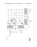
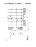
[0004]Referring to FIGS. 1 and 2, there are illustrated scheduler decision abstractions. The examples of FIGS. 1 and 2 are for scheduling a crossbar switch. The crossbar switch 10 includes input ports 12, output ports 14 and a switch fabric 16. Input ports 12 can be configures as x* ports 18 and x4 ports 19. Output ports 14 can also be configured as x8 ports 20 and x4 ports 21. The spotted dots and checkered dots represent request connections on the white and black clock phase respectively. For crossbar scheduling only one dot per phase (color), per row and column. With FIFO queuing, only one request per row per phase (color). A logical port for a 1×8 port consists of to ISF connections. Then dots 22 (spotted) represent requests for the white clock tick, while dots 24 (checkered) represent requests for the black clock tick. The dot 25 represents a request for both black and white clock ticks. The ellipses 26, 28 and 30 in the figures illustrate what a consistent decision would be. That is, in FIG. 1, ellipse 26 represents a x8 port to a x8 port connection, which preservers order and bandwidth of data switched. While ellipse 2 represents a x4 port to a x8 port connection, which also preservers order and bandwidth of data switched. Similarly, in FIG. 2, ellipse 30 represents a x8 port to a x4 port connection, which once again preservers order and bandwidth of data switched.
[0005]In order to simplify the ingress and egress queue management, it is desirable to make the scheduling decision such that the logical ports make consistent port selections.
SUMMARY OF THE INVENTION
[0006]An object of the present invention is to provide an improved bifurcate arbiter.
[0007]In accordance with an aspect of the present invention there is provided an arbiter for a space switch comprising a two buffers, a media access controller having data outputs coupled to the two buffers, and two control outputs coupled to respective buffers for buffering input data at a clock rate one-half that of the input data and a switch fabric connected to the two buffers for matching buffer data throughput with switch data throughput, the arbiter comprising first and second schedulers, each scheduler includes a plurality of inputs for connection to the two buffers for receiving requests, a plurality of outputs for granting requests and a plurality of inter connections to each of the plurality of schedulers for informing them of grants and logic for logically grouping input ports associated with a bifurcate input port, logically grouping output ports associated with a bifurcate output port, establishing round robin pointers for each of two alternate clock ticks for tracking next allowable requests and on one clock tick allowing connection requests from input ports to output ports and accepting a connection request in dependence upon the grouping of the input and output ports and the round robin pointer.
[0008]In accordance with a further aspect of the present invention there is provided a method of switching for a space switch having bifurcate ports and ports, the method comprising the steps of logically grouping input ports associated with a bifurcate input port, logically grouping output ports associated with a bifurcate output port, establishing round robin pointers for each of two alternate clock ticks for tracking next allowable requests, on one clock tick allowing connection requests from input ports to output ports and accepting a connection request in dependence upon the grouping of the input and output ports and the round robin pointer.
[0009]The arbiter can be generalized to an 2n-furcated switch having 2n-furcated ports where n is a positive integral power of 2.
[0010]By matching buffer throughput and switch fabric throughput a more effective use of buffers and fabric bandwidth is made.
BRIEF DESCRIPTION OF THE DRAWINGS
[0011]The present invention will be further understood from the following detailed description with reference to the drawings in which:
[0012]FIG. 1 illustrates a first scheduler decision abstraction;
[0013]FIG. 2 illustrates a second scheduler decision abstraction;
[0014]FIG. 3 illustrates a bifurcate space switch in accordance with a co-pending application in a first configuration;
[0015]FIG. 4 illustrates a bifurcate space switch in accordance with a co-pending application in a second configuration;
[0016]FIG. 5 illustrates a bifurcate arbiter in accordance with an embodiment of the present invention;
[0017]FIG. 6 illustrate switching for the bifurcate space switch of FIG. 3; and
[0018]FIG. 7 illustrate switching for the bifurcate space switch of FIG. 4.
DETAILED DESCRIPTION OF THE PREFERRED EMBODIMENT
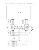
[0019]Referring to FIG. 3 there is illustrated a bifurcate space switch in accordance with a co-pending application in a first configuration. The bifurcate space switch 32 includes a bifurcate buffer 40 and an ISF 50. The bifurcate buffer 40, shown configured as a 1×8 port, includes a media access controller (MAC) 42 receiving input from serializer/de-serializer (SERDES) (not shown in FIG. 3) and outputting four 16-bit wide lanes to each of x64 RAM 44 and 46, controlled by lines 48a and 48b, respectively. The control line 48b is coupled to the x64 RAM 46 via a MUX 52, which is used to change configuration of the bifurcate buffer 40.
[0020]In operation, the data is written into two-x64 250 MHz dual port RAM 44 and 46. The memory management of the MAC 42 generates different addresses for each bank. In the configuration shown, the 1×8 port 40 is connected to the ISF 50 in such a way as to ensure that the external bandwidth and ISF bandwidth are the same, and that both buffers 44 and 46 are used.
[0021]Referring to FIG. 4 there is illustrated a bifurcate space switch in accordance with a co-pending application in a second configuration. In the 2×4 configuration, the bifurcate space switch 32 includes a x2×4 bifurcate buffer 40 having a first media access controller (MAC) 42 receiving input from serializer/de-serializer (SERDES) and outputting four 16-bit wide lanes to x64 RAM 44, controlled by line 48a. The 2×4 bifurcate buffer 40 also includes a second media access controller (MAC) 54 receiving input from the lower four serializer/de-serializer (SERDES) and outputting four 16-bit wide lanes to x64 RAM 46, controlled by line 56. Hence, in this example the 1×8 port 40 bifurcates to 2×4 ports.
[0022]In operation, the upper x8 MAC 42 is configured to run in x4 mode. Here each buffer 44 and 46 is managed by its respective MAC 42 and 54. Again note that both buffers are used and the ISF bandwidth equals the port bandwidth.
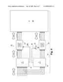
[0023]Referring to FIG. 5, a bifurcate arbiter in accordance with an embodiment of the present invention. The bifurcate arbiter includes two schedulers, a white scheduler 60 and a black scheduler 62, where white and black represent alternate clock ticks. Each scheduler includes a plurality of inputs 64 for requests from the ports, an input for port configuration 66 a plurality of outputs 68 for grants to the ports and a status output 70. A plurality of interconnects 72 between the two schedulers ensures that the grants are coordinated.
[0024]In operation, the two schedulers 60 and 62 work in a time-division multiplex (TDM) fashion. Each ingress port makes one request, via inputs 64, by holding REQ high for one tick. During this tick the desired output port is encoded on the Port bus. The busy[5:0] 70 indicates which egress ports are in use, so that ingress ports will not request those ports. When the last tick of data occurs, the End Of Packet (EOP) is high, telling the scheduler to drop the busy bit for that port, so the ingress ports can request the egress port on the next clock tick.
[0025]Arbitration is accomplished on a per egress port basis. If multiple ingress ports request the same egress port, the ingress port is selected in a round robin fashion. In order to keep the scheduling decisions consistent, any time an egress port makes a port selection, grant high for one tick, this is passed to the other scheduler along with the ingress port selected via interconnects 72.
[0026]Referring to FIG. 6, there is illustrated a method of synchronizing the bifurcate arbiter of FIG. 5 for x8 ports. The method for keeping the schedulers 60 and 62 synchronized is now described herein below. Consider the x8 port 80 (ports 1 and 2) in FIG. 6. On the white tick only the white connections are active, the black are shown for reference only. The columns of numbers, [1,2,3,4,5,6], represent the round robin pointer for each port, and black and white clock phases, 82 and 84. Note for simplicity, only output to ports (1 and 2) 86 and 88 constituting a x8 port 90, is shown as the port under consideration.
Tick 0, White 92:
[0027]1. x8 port (1+2) 80 sending 1/2 bandwidth to x8 port (1+2) 902. x4 port (3) sending full bandwidth to x8 port (1+2) 903. the white port 2-port 2 connection indicates EOP
Tick 1, Black 94:
[0028]1. the black port 1-port 1 connection indicates EOP2. the black port 3-port 2 connection indicates EOP3. the white port 4-port 2 connection is requested and selected (port 4 is closest to pointer)4. the white round robin pointer for port 2 advances to port 5 (because port 4 was selected)5. the black round robin pointer for port 2 advances to port 4 (white port 4 was just selected)6. the white port 5-port 2 connection is requested and not selected
Tick 2, White 96:
[0029]1. the white 3-1 connection indicates EOP2. the black 4-1 connection is requested and is selected (port 4 is closest to pointer)3. the black round robin pointer for port 1 advances to port 5 (port 4 was just selected)4. the black 2-1 connection is requested and not selected5. the black 5-2 connection is requested and is selected (port 4 is closest to pointer)6. the black round robin pointer for port 2 advances to port 5 (port 4 was just selected)
Tick 3, Black 98:
[0030]1. the white 6-1 connection is requested and is selected (only request)2. the white round robin pointer for port 1 advances to port 1 (port 6 was just selected)
[0031]Note that for x8 ports pointer advancement, the group is treated as one location.
[0032]Referring to FIG. 7, there is illustrated a method of synchronizing the bifurcate arbiter of FIG. 5 for x4 ports. Note for simplicity, only output to port 3 constituting a x4 port 100, is shown as the port under consideration. As in FIG. 6, on the white tick only the white connections are active, the black are shown for reference only. The columns of numbers, [1,2,3,4,5,6], represent the round robin pointer for each port, and black and white clock phases, 110 and 112.
[0033]Packets switching to a x4 port is now described.
Tick 0, White 100:
[0034]1. x8 port (1+2) 80 sending 1/2 bandwidth to x4 port (3) 1002. the white port 1-port 3 connection indicates EOP
Tick 1, Black 104:
[0035]1. the black port 2-port 3 connection indicates EOP2. the black port 4-port 3 connection is requested and is selected (port 4 is closest to pointer)3. the black round robin pointer for port 3 advances to port 5 (because port 4 was selected)4. the white round robin pointer for port 3 advances to port 4 (because port 4 was just selected)5. the white port 6-port 3 connection is requested and not selected
Tick 2, White 106:
[0036]1. the white port 4-port 3 connection is requested and is selected (port 4 is closest to pointer)2. the black round robin pointer for port 1 advances to port 5 (because port 4 was just selected)3. the black port 2-port 3 connection is requested and not selected the black port 5-port 3 connection is requested and not selected
Tick 3, Black 108:
[0037]1. data flows port 4-port 3
[0038]Numerous modifications, variations and adaptations may be made to the particular embodiments described above without departing from the scope patent disclosure, which is defined in the claims.
Claims:
1. A method of switching for a space switch having bifurcate ports and
ports, the method comprising the steps of:logically grouping input ports
associated with a bifurcate input port;logically grouping output ports
associated with a bifurcate output port;establishing round robin pointers
for each of two alternate clock ticks for tracking next allowable
requestson one clock tick allowing connection requests from input ports
to output ports; andaccepting a connection request in dependence upon the
grouping of the input and output ports and the round robin pointer.
2. The method of claim 1 wherein the step of accepting a connection request includes a step of moving the round robin pointer in dependence upon the grouping of the output ports.
3. The method of claim 2 wherein a bifurcate input port connected to a bifurcate output port.
4. The method of claim 2 wherein a single input port connected to a bifurcate output port.
5. The method of claim 2 wherein a bifurcate input port connected to an single output port.
6. An arbiter for a space switch comprising a two buffers, a media access controller having data outputs coupled to the two buffers, and two control outputs coupled to respective buffers for buffering input data at a clock rate one-half that of the input data and a switch fabric connected to the two buffers for matching buffer data throughput with switch data throughput, the arbiter comprising first and second schedulers, each scheduler includes a plurality of inputs for connection to the two buffers for receiving requests, a plurality of outputs for granting requests and a plurality of inter connections to each of the plurality of schedulers for informing them of grants and logic for logically grouping input ports associated with a bifurcate input port, logically grouping output ports associated with a bifurcate output port, for establishing round robin pointers for each of two alternate clock ticks for tracking next allowable requests and for on one clock tick allowing connection requests from input ports to output ports and accepting a connection request in dependence upon the grouping of the input and output ports and the round robin pointer.
7. The arbiter of claim 6 wherein the logic includes means for moving the round robin pointer in dependence upon the grouping of the output ports.
8. The arbiter of claim 7 wherein the logic allows a bifurcate input port to be connected to a bifurcate output port.
9. The arbiter of claim 7 wherein the logic allows a single input port to be connected to a bifurcate output port.
10. The arbiter of claim 7 wherein the logic allows a bifurcate input port to be connected to a single output port.
11. A method of switching for a space switch, the method comprising the steps of:logically grouping input ports associated with a 2.sup.n-furcated input port;logically grouping output ports associated with a 2.sup.n-furcated output port;establishing round robin pointers for each of n clock ticks for tracking next allowable requests;on a clock tick allowing connection requests from input ports to output ports; andaccepting a connection request in dependence upon the grouping of the input and output ports and the round robin pointer.
12. The method of claim 11 wherein the step of accepting a connection request includes a step of moving the round robin pointer in dependence upon the grouping of the output ports.
13. The method of claim 12 wherein a 2.sup.n-furcate input port connected to a 2.sup.n-furcate output port.
14. The method of claim 12 wherein a single input port connected to a 2.sup.n-furcate output port.
15. The method of claim 12 wherein a 2.sup.n-furcate input port connected to a single output port.
16. An arbiter for a space switch comprising a plurality 2.sup.n of buffers, a media access controller having data outputs coupled to the plurality 2.sup.n of buffers, and a plurality of control outputs coupled to respective buffers for buffering input data at a clock rate one-2.sup.nth that of the input data and a switch fabric connected to the plurality of 2.sup.n buffers for matching buffer data throughput with switch data throughput, the arbiter comprising a plurality of 2.sup.n schedulers, each scheduler includes a plurality of inputs for connection to the buffers for receiving requests, a plurality of outputs for granting requests and a plurality of inter connections to each of the plurality of schedulers for informing them of grants and logic for logically grouping input ports associated with an 2.sup.n-furcated input port, logically grouping output ports associated with an 2.sup.n-furcated output port, establishing round robin pointers for each of 2.sup.n clock ticks for tracking next allowable requests and on a clock tick allowing connection requests from input ports to output ports and accepting a connection request in dependence upon the grouping of the input and output ports and the round robin pointers.
17. The arbiter of claim 16 wherein the logic includes means for moving the round robin pointer in dependence upon the grouping of the output ports.
18. The arbiter of claim 17 wherein the logic allows an 2.sup.n-furcated input port to be connected to an 2.sup.n-furcated output port.
19. The arbiter of claim 17 wherein the logic allows a single input port to be connected to an 2.sup.n-furcated output port.
20. The arbiter of claim 17 wherein the logic allows an n-furcated input port to be connected to a single output port.
Description:
CROSS-REFERENCE TO RELATED APPLICATIONS
[0001]A claim of priority is made to U.S. Provisional Patent Application Ser. No. 60/894,710, entitled Bifuracate Arbiter, filed Mar. 14, 2007.
FIELD OF THE INVENTION
[0002]The present invention relates to arbiters and is particularly concerned with arbiters for bifurcate space switches.
BACKGROUND OF THE INVENTION
[0003]Peripheral Component Interconnect Express, PCIe 2.0 specifies 5.0 Gigbit/s symbol rate per lane. Multiple lanes can be used to fabricate larger port bandwidths. For example, x4 port would have an aggregate symbol rate of 20 G, and a bit rate of 16 G, 8b10b coding is used. A x8 port would have an aggregate symbol rate of 40 G, and a bit rate of 32 G. There are other serial interconnect protocols, for example serial rapid IO and Ethernet that have similar properties.
[0004]Referring to FIGS. 1 and 2, there are illustrated scheduler decision abstractions. The examples of FIGS. 1 and 2 are for scheduling a crossbar switch. The crossbar switch 10 includes input ports 12, output ports 14 and a switch fabric 16. Input ports 12 can be configures as x* ports 18 and x4 ports 19. Output ports 14 can also be configured as x8 ports 20 and x4 ports 21. The spotted dots and checkered dots represent request connections on the white and black clock phase respectively. For crossbar scheduling only one dot per phase (color), per row and column. With FIFO queuing, only one request per row per phase (color). A logical port for a 1×8 port consists of to ISF connections. Then dots 22 (spotted) represent requests for the white clock tick, while dots 24 (checkered) represent requests for the black clock tick. The dot 25 represents a request for both black and white clock ticks. The ellipses 26, 28 and 30 in the figures illustrate what a consistent decision would be. That is, in FIG. 1, ellipse 26 represents a x8 port to a x8 port connection, which preservers order and bandwidth of data switched. While ellipse 2 represents a x4 port to a x8 port connection, which also preservers order and bandwidth of data switched. Similarly, in FIG. 2, ellipse 30 represents a x8 port to a x4 port connection, which once again preservers order and bandwidth of data switched.
[0005]In order to simplify the ingress and egress queue management, it is desirable to make the scheduling decision such that the logical ports make consistent port selections.
SUMMARY OF THE INVENTION
[0006]An object of the present invention is to provide an improved bifurcate arbiter.
[0007]In accordance with an aspect of the present invention there is provided an arbiter for a space switch comprising a two buffers, a media access controller having data outputs coupled to the two buffers, and two control outputs coupled to respective buffers for buffering input data at a clock rate one-half that of the input data and a switch fabric connected to the two buffers for matching buffer data throughput with switch data throughput, the arbiter comprising first and second schedulers, each scheduler includes a plurality of inputs for connection to the two buffers for receiving requests, a plurality of outputs for granting requests and a plurality of inter connections to each of the plurality of schedulers for informing them of grants and logic for logically grouping input ports associated with a bifurcate input port, logically grouping output ports associated with a bifurcate output port, establishing round robin pointers for each of two alternate clock ticks for tracking next allowable requests and on one clock tick allowing connection requests from input ports to output ports and accepting a connection request in dependence upon the grouping of the input and output ports and the round robin pointer.
[0008]In accordance with a further aspect of the present invention there is provided a method of switching for a space switch having bifurcate ports and ports, the method comprising the steps of logically grouping input ports associated with a bifurcate input port, logically grouping output ports associated with a bifurcate output port, establishing round robin pointers for each of two alternate clock ticks for tracking next allowable requests, on one clock tick allowing connection requests from input ports to output ports and accepting a connection request in dependence upon the grouping of the input and output ports and the round robin pointer.
[0009]The arbiter can be generalized to an 2n-furcated switch having 2n-furcated ports where n is a positive integral power of 2.
[0010]By matching buffer throughput and switch fabric throughput a more effective use of buffers and fabric bandwidth is made.
BRIEF DESCRIPTION OF THE DRAWINGS
[0011]The present invention will be further understood from the following detailed description with reference to the drawings in which:
[0012]FIG. 1 illustrates a first scheduler decision abstraction;
[0013]FIG. 2 illustrates a second scheduler decision abstraction;
[0014]FIG. 3 illustrates a bifurcate space switch in accordance with a co-pending application in a first configuration;
[0015]FIG. 4 illustrates a bifurcate space switch in accordance with a co-pending application in a second configuration;
[0016]FIG. 5 illustrates a bifurcate arbiter in accordance with an embodiment of the present invention;
[0017]FIG. 6 illustrate switching for the bifurcate space switch of FIG. 3; and
[0018]FIG. 7 illustrate switching for the bifurcate space switch of FIG. 4.
DETAILED DESCRIPTION OF THE PREFERRED EMBODIMENT
[0019]Referring to FIG. 3 there is illustrated a bifurcate space switch in accordance with a co-pending application in a first configuration. The bifurcate space switch 32 includes a bifurcate buffer 40 and an ISF 50. The bifurcate buffer 40, shown configured as a 1×8 port, includes a media access controller (MAC) 42 receiving input from serializer/de-serializer (SERDES) (not shown in FIG. 3) and outputting four 16-bit wide lanes to each of x64 RAM 44 and 46, controlled by lines 48a and 48b, respectively. The control line 48b is coupled to the x64 RAM 46 via a MUX 52, which is used to change configuration of the bifurcate buffer 40.
[0020]In operation, the data is written into two-x64 250 MHz dual port RAM 44 and 46. The memory management of the MAC 42 generates different addresses for each bank. In the configuration shown, the 1×8 port 40 is connected to the ISF 50 in such a way as to ensure that the external bandwidth and ISF bandwidth are the same, and that both buffers 44 and 46 are used.
[0021]Referring to FIG. 4 there is illustrated a bifurcate space switch in accordance with a co-pending application in a second configuration. In the 2×4 configuration, the bifurcate space switch 32 includes a x2×4 bifurcate buffer 40 having a first media access controller (MAC) 42 receiving input from serializer/de-serializer (SERDES) and outputting four 16-bit wide lanes to x64 RAM 44, controlled by line 48a. The 2×4 bifurcate buffer 40 also includes a second media access controller (MAC) 54 receiving input from the lower four serializer/de-serializer (SERDES) and outputting four 16-bit wide lanes to x64 RAM 46, controlled by line 56. Hence, in this example the 1×8 port 40 bifurcates to 2×4 ports.
[0022]In operation, the upper x8 MAC 42 is configured to run in x4 mode. Here each buffer 44 and 46 is managed by its respective MAC 42 and 54. Again note that both buffers are used and the ISF bandwidth equals the port bandwidth.
[0023]Referring to FIG. 5, a bifurcate arbiter in accordance with an embodiment of the present invention. The bifurcate arbiter includes two schedulers, a white scheduler 60 and a black scheduler 62, where white and black represent alternate clock ticks. Each scheduler includes a plurality of inputs 64 for requests from the ports, an input for port configuration 66 a plurality of outputs 68 for grants to the ports and a status output 70. A plurality of interconnects 72 between the two schedulers ensures that the grants are coordinated.
[0024]In operation, the two schedulers 60 and 62 work in a time-division multiplex (TDM) fashion. Each ingress port makes one request, via inputs 64, by holding REQ high for one tick. During this tick the desired output port is encoded on the Port bus. The busy[5:0] 70 indicates which egress ports are in use, so that ingress ports will not request those ports. When the last tick of data occurs, the End Of Packet (EOP) is high, telling the scheduler to drop the busy bit for that port, so the ingress ports can request the egress port on the next clock tick.
[0025]Arbitration is accomplished on a per egress port basis. If multiple ingress ports request the same egress port, the ingress port is selected in a round robin fashion. In order to keep the scheduling decisions consistent, any time an egress port makes a port selection, grant high for one tick, this is passed to the other scheduler along with the ingress port selected via interconnects 72.
[0026]Referring to FIG. 6, there is illustrated a method of synchronizing the bifurcate arbiter of FIG. 5 for x8 ports. The method for keeping the schedulers 60 and 62 synchronized is now described herein below. Consider the x8 port 80 (ports 1 and 2) in FIG. 6. On the white tick only the white connections are active, the black are shown for reference only. The columns of numbers, [1,2,3,4,5,6], represent the round robin pointer for each port, and black and white clock phases, 82 and 84. Note for simplicity, only output to ports (1 and 2) 86 and 88 constituting a x8 port 90, is shown as the port under consideration.
Tick 0, White 92:
[0027]1. x8 port (1+2) 80 sending 1/2 bandwidth to x8 port (1+2) 902. x4 port (3) sending full bandwidth to x8 port (1+2) 903. the white port 2-port 2 connection indicates EOP
Tick 1, Black 94:
[0028]1. the black port 1-port 1 connection indicates EOP2. the black port 3-port 2 connection indicates EOP3. the white port 4-port 2 connection is requested and selected (port 4 is closest to pointer)4. the white round robin pointer for port 2 advances to port 5 (because port 4 was selected)5. the black round robin pointer for port 2 advances to port 4 (white port 4 was just selected)6. the white port 5-port 2 connection is requested and not selected
Tick 2, White 96:
[0029]1. the white 3-1 connection indicates EOP2. the black 4-1 connection is requested and is selected (port 4 is closest to pointer)3. the black round robin pointer for port 1 advances to port 5 (port 4 was just selected)4. the black 2-1 connection is requested and not selected5. the black 5-2 connection is requested and is selected (port 4 is closest to pointer)6. the black round robin pointer for port 2 advances to port 5 (port 4 was just selected)
Tick 3, Black 98:
[0030]1. the white 6-1 connection is requested and is selected (only request)2. the white round robin pointer for port 1 advances to port 1 (port 6 was just selected)
[0031]Note that for x8 ports pointer advancement, the group is treated as one location.
[0032]Referring to FIG. 7, there is illustrated a method of synchronizing the bifurcate arbiter of FIG. 5 for x4 ports. Note for simplicity, only output to port 3 constituting a x4 port 100, is shown as the port under consideration. As in FIG. 6, on the white tick only the white connections are active, the black are shown for reference only. The columns of numbers, [1,2,3,4,5,6], represent the round robin pointer for each port, and black and white clock phases, 110 and 112.
[0033]Packets switching to a x4 port is now described.
Tick 0, White 100:
[0034]1. x8 port (1+2) 80 sending 1/2 bandwidth to x4 port (3) 1002. the white port 1-port 3 connection indicates EOP
Tick 1, Black 104:
[0035]1. the black port 2-port 3 connection indicates EOP2. the black port 4-port 3 connection is requested and is selected (port 4 is closest to pointer)3. the black round robin pointer for port 3 advances to port 5 (because port 4 was selected)4. the white round robin pointer for port 3 advances to port 4 (because port 4 was just selected)5. the white port 6-port 3 connection is requested and not selected
Tick 2, White 106:
[0036]1. the white port 4-port 3 connection is requested and is selected (port 4 is closest to pointer)2. the black round robin pointer for port 1 advances to port 5 (because port 4 was just selected)3. the black port 2-port 3 connection is requested and not selected the black port 5-port 3 connection is requested and not selected
Tick 3, Black 108:
[0037]1. data flows port 4-port 3
[0038]Numerous modifications, variations and adaptations may be made to the particular embodiments described above without departing from the scope patent disclosure, which is defined in the claims.
User Contributions:
Comment about this patent or add new information about this topic:
Images included with this patent application:
 |  |
 |  |
 |  |
 |
| Similar patent applications: | |
| Date | Title |
|---|---|
| 2010-06-24 | Virtual private network based upon multi-protocol label switching adapted to measure the traffic flowing between single rate zones |
| 2008-08-28 | Bifurcate space switch |
| 2008-11-06 | Harq failure indication over iub-interface |
| 2008-12-04 | Compact mpe-fec erasure location cache memory for dvb-h receiver |
| 2009-02-19 | Fabric generated monotonically increasing identifier |
| New patent applications in this class: | |
| Date | Title |
|---|---|
| 2018-01-25 | Network device and a method for networking |
| 2016-12-29 | Port monitoring system |
| 2016-07-14 | Customer controlled video network |
| 2016-07-07 | Port status synchronization method, related device, and system |
| 2016-06-30 | System and method for improved communication in a storage network |
| Top Inventors for class "Multiplex communications" | |
| Rank | Inventor's name |
|---|---|
| 1 | Peter Gaal |
| 2 | Wanshi Chen |
| 3 | Tao Luo |
| 4 | Hanbyul Seo |
| 5 | Jae Hoon Chung |