Patent application title: Identification Document with a Contactless Rfid Chip
Inventors:
Volker Timm (Pinneberg, DE)
Kim Nguyen (Berlin, DE)
Assignees:
KONINKLIJKE PHILIPS ELECTRONICS N.V.
IPC8 Class: AG05B1900FI
USPC Class:
340 58
Class name: Selective intelligence comparison for controlling authentication (e.g., identity)
Publication date: 2008-09-11
Patent application number: 20080218308
Inventors list |
Agents list |
Assignees list |
List by place |
Classification tree browser |
Top 100 Inventors |
Top 100 Agents |
Top 100 Assignees |
Usenet FAQ Index |
Documents |
Other FAQs |
Patent application title: Identification Document with a Contactless Rfid Chip
Inventors:
Volker Timm
Kim Nguyen
Agents:
NXP, B.V.;NXP INTELLECTUAL PROPERTY DEPARTMENT
Assignees:
KONINKLIJKE PHILIPS ELECTRONICS N.V.
Origin: SAN JOSE, CA US
IPC8 Class: AG05B1900FI
USPC Class:
340 58
Abstract:
To provide an identification document, particularly a passport, in which
at least one contactless RFID chip (10) and an antenna (12) connected
thereto are integrated on a page of the identification document, an
additional layer (22) mechanically reinforcing the RFID chip is situated
at the area of the RFID chip (10) on the page, thus providing an
arrangement with which the RFID chip can withstand mechanical stress for
years on end.Claims:
1. An identification document having multiple pages, wherein at least one
contactless RFID chip and an antenna connected thereto are integrated on
a page of the identification document, characterized in that an
additional layer mechanically reinforcing the RFID chip is situated at
the area of the RFID chip on the page.
2. An identification document as claimed in claim 1, characterized in that the additional layer mechanically reinforcing the RFID chip is provided on the facing side of the page of the identification document.
3. An identification document as claimed in claim 1, characterized in that the additional layer mechanically reinforcing the RFID chip is made of a corrosion-free material such as a stainless steel-sheet.
4. An identification document as claimed in claim 1, characterized in that the rigidity of the layer mechanically reinforcing the RFID chip gradually decreases from its center towards its edge.
5. An identification document as claimed in claim 1, characterized in that the additional layer mechanically reinforcing the RFID chip has a curved or serrated outer edge.
6. An identification document as claimed in claim 1, characterized in that a large number of apertures has been punched from the additional layer mechanically reinforcing the RFID chip.
7. An identification document as claimed in claim 1, wherein the identification document is a passport.
Description:
[0001]The invention relates to an identification document, particularly a
passport, comprising a contactless RFID chip as defined in the
pre-characterizing part of claim 1.
[0002]New generations of passports will have biometrical data stored on an RFID chip integrated in the document. Passport control, for example at a border crossing, may be performed by scanning the passport and reading the chip. It takes only a few seconds to read the chip and, consequently, leads to a very swift identification of the passport owner. In this respect, it is relevant how to manufacture a passport with an embedded chip and an antenna so as to withstand loads, such as stamping and folding, for a comparatively long period of time, for example, 10 years.
[0003]The robust design of chip cards such as, for example, multimedia cards or smart cards is known from the prior art. Such cards have a card body made of a synthetic material and incorporating a semiconductor chip.
[0004]U.S. Pat. No. 5,544,014 describes an arrangement of a microchip in a card body in which the microchip edges are tapered. It is achieved by the reducing thickness that the durability is enhanced, also under strong loads.
[0005]WO 03/058713 describes a mechanism of fixing a microchip on a chip carrier. An outer fixation edge of the chip carrier is reinforced by means of an additional layer. In a preferred embodiment, this reinforcement has an inner edge which does not extend linearly but is, for example, curved or serrated. The sensitivity to breakage is thereby reduced at the transition between the reinforced and the inner area of the chip carrier.
[0006]Moreover, the prior art discloses methods in which the stability of the connection between the different layers in the smart card is enhanced in that at least one layer is apertured. Such methods are known from, for example, JP2002 31615 and JP2002 216097.
[0007]US 2003/0,132,302 describes a contactless RFID memory card in which (when viewing the chip from the top) a small metal plate is provided behind the chip, which metal plate mechanically reinforces the surroundings of the chip and thus prevents destruction.
[0008]Microchips are conventionally embedded in chip cards on a fundamental body which itself is generally more rigid than the material in which it is to be embedded. For normal cards made of synthetic material (see ISO 7816, ISO 14 443), this mechanical carrier has the overall size of the synthetic material card and comprises both the antenna for the contactless operation and the microchip itself. The synthetic material card has a high mechanical rigidity so that the microchip is hardly bent and, consequently, does not tend to break.
[0009]In contrast, the new generations of passports or identification cards neither have a synthetic material card format (as in ISO 7816 or ISO 14 443), nor their mechanical rigidity. Even very thinly ground microchips, with stringent requirements imposed on their bending strength, would not be resistant to stress for years without further measures. The semiconductor materials such as silicon used for manufacturing microchips are very brittle and thus liable to breakage and are not very resistant to complex bending loads.
[0010]It is an object of the invention to provide an arrangement in which the RFID chip can withstand stress for years. According to the invention, this object is achieved by means of an identification document as defined in the characterizing part of claim 1. One page of this identification document is provided with at least one contactless RFID chip and an antenna connected thereto by means of bonding wires. Since an additional layer mechanically reinforcing the RFID chip is provided at the area of the RFID chip on the page, it is advantageously achieved that the basic chip material is protected from breakage.
[0011]In a preferred embodiment of the invention, the additional reinforcing layer is made of a stainless material such as stainless steel or the like. This allows years of use without a change of the mechanical condition of the layer. A layer of stainless steel-sheet (V2A) may be formed in a very thin size. Corrosion-free materials which are suitable for manufacturing the additional layer are, for example, V2A, V4A, GfK or carbon fiber. Since the mechanically reinforcing layer is made of a material having a high thermal capacity, it can also advantageously conduct heat which is generated when operating the RFID chip. This may lead to a longer lifetime of the RFID chip.
[0012]In a further preferred embodiment of the invention, the additionally reinforcing layer has a curved or serrated outer edge. It is thereby ensured that, with a uniform thickness, the rigidity of the layer gradually decreases from the middle, where the center of the chip is supported, towards its outer edge. In the case of mechanical stress, i.e. when a force acts on the outer edge of the additional layer, the page of the document is bent, with the curvature being smallest in the middle and gradually increasing towards the edge. Consequently, little stress is exerted on the chip which thus does not tend to break and is neither urged into the embedding material, which would also entail a risk of breakage.
[0013]A very simple realization of the arrangement described above is obtained in that the additional reinforcing layer is apertured. The adhesives used for connecting the two layers can pass through these apertures. This ensures a stronger adhesion of the additional reinforcing layer as well as of the externally connecting cover sheet on the fundamental body of the chip.
[0014]These and other aspects of the invention are apparent from and will be elucidated with reference to the embodiments described hereinafter.
[0015]In the drawings:
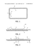
[0016]FIG. 1 shows the arrangement of an RFID chip and an antenna on a prior-art card made of synthetic material;
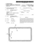
[0017]FIG. 2 shows the arrangement of an RFID chip and a layer mechanically reinforcing the RFID chip without using a bending force;
[0018]FIG. 3 shows the arrangement of an RFID chip and a layer mechanically reinforcing the RFID chip while using a bending force;
[0019]FIG. 4 shows a geometrical shape of the mechanically reinforcing layer;
[0020]FIG. 5 shows a further geometrical shape of the mechanically reinforcing layer, and
[0021]FIG. 6 shows the mechanically reinforcing layer with a large number of apertures.
[0022]FIG. 1 shows the arrangement of an RFID system of the prior art. An RFID chip 10 and a lateral coil 12 operating as an antenna are interconnected by means of the bonding wires 14 and 16. The system is provided on a chip card body 18 made of a synthetic material. Since the synthetic material itself has a relatively high rigidity, the RFID chip is protected from breakage. The problem on which the invention is based is caused in that, as compared with the first-mentioned case, the carrier material has an essentially lower rigidity when an RFID chip is embedded in an identification document.
[0023]FIG. 2 shows the mechanical reinforcement of the RFID chip (shown without bending load). Again, an RFID chip 10 and an antenna 12, which are interconnected by means of the bonding wires 14 and 16, are provided on a module body 20 which is made of a synthetic material and is softer than the material used for the normal smart cards. A mechanically reinforcing layer 22 is now provided on the side of the page of the identification document facing the RFID chip. Typically, the arrangement shown in FIG. 2 is surrounded by additional protective layers at the top and bottom. Without the mechanically reinforcing layer 22, the rigidity of the module body 20 should be chosen to be essentially higher, with the risk that the consecutive layers might come off. In the event of this delamination, shearing forces would be produced on the surface of the embedded RFID chip, which forces would damage both the connections 14 and 16 to the antenna and the RFID chip 10 itself.
[0024]FIG. 3 shows the same arrangement while using a bending force P24. The page of the identification document, denoted overall by the reference numeral 100, is considered to be fixed at the area of the center of the RFID chip 10 by means of a holding mechanism 26. Since the rigidity of the mechanically reinforcing layer 22 continuously decreases from the center of the RFID chip 10 towards the rim of the layer 22, the bending radius gradually increases from the inner side to the outer side. Consequently, the relative deflections of the various regions are smallest at the area of the RFID chip 10. This minimizes the risk of breakage of the chip.
[0025]FIG. 4 shows a possible geometrical shape of the mechanically reinforcing layer 22 having an appropriate behavior. The outer edge 30 of the mechanically reinforcing layer is curved, with the rounded corners having a maximal radius of curvature so as to prevent the mechanically reinforcing layer 22 from being urged into the embedding material of the module body 20. FIG. 4 shows the fundamental shape of the reinforcing layer 22 as a rectangle. However, it may be alternatively circular, as shown in FIG. 5.
[0026]FIG. 6 shows the mechanically reinforcing layer 22 with a large number of apertures 32. It is achieved by this measure that the mechanically reinforcing layer 22, which is provided by means of a suitable adhesive, adheres more rigidly to the surrounding layers, i.e. to the module body 20 and the enveloping material. The adhesive passes through the apertures 32 and connects with the neighboring material so as to prevent delamination. This arrangement minimizes the risk of a delamination having the consequences as described hereinbefore.
User Contributions:
comments("1"); ?> comment_form("1"); ?>Inventors list |
Agents list |
Assignees list |
List by place |
Classification tree browser |
Top 100 Inventors |
Top 100 Agents |
Top 100 Assignees |
Usenet FAQ Index |
Documents |
Other FAQs |
User Contributions:
Comment about this patent or add new information about this topic:
Images included with this patent application:
 |  |
 |
| Similar patent applications: | |
| Date | Title |
|---|---|
| 2012-02-23 | Multifunctional doorbell with controllable lighting |
| 2012-05-03 | Identifying locations within a building using a mobile device |
| 2010-06-17 | Payment skin with contactless chip |
| 2011-12-29 | System and method for identifying electrical equipment using wireless receivers |
| 2012-04-05 | Application launching in conjunction with an accessory |
| New patent applications in this class: | |
| Date | Title |
|---|---|
| 2016-03-24 | Authentication systems and methods |
| 2016-03-10 | Electronic apparatus |
| 2016-02-11 | Systems and methods for end-to-end secure link between a near-field communication (nfc) chip and server |
| 2015-11-05 | Systems and methods for use in authenticating an object |
| 2015-10-15 | Devices, systems and methods for authenticated intravascular device use and reuse |
| New patent applications from these inventors: | |
| Date | Title |
|---|---|
| 2017-06-15 | Distributed authentication system |
| 2010-09-02 | Method for protection of a chip card from unauthorized use, chip card and chip card terminal |
| 2009-12-03 | Data carrier with a chip and a plurality of sensors |
| Top Inventors for class "Communications: electrical" | |
| Rank | Inventor's name |
|---|---|
| 1 | Lowell L. Wood, Jr. |
| 2 | Roderick A. Hyde |
| 3 | Juan Manuel Cruz-Hernandez |
| 4 | John R. Tuttle |
| 5 | Jordin T. Kare |