Patent application title: Storage device for battery modules
Inventors:
Yoshiro Shimoyama (Chiba, JP)
Assignees:
Hyundai Motor Company
Kia Motors Corporation
HYUNDAI MOTOR JAPAN R&D CENTER, INC.
IPC8 Class: AB65D8588FI
USPC Class:
206703
Class name: Special receptacle or package holder for a removable electrical component for a battery
Publication date: 2008-09-11
Patent application number: 20080217209
Inventors list |
Agents list |
Assignees list |
List by place |
Classification tree browser |
Top 100 Inventors |
Top 100 Agents |
Top 100 Assignees |
Usenet FAQ Index |
Documents |
Other FAQs |
Patent application title: Storage device for battery modules
Inventors:
Yoshiro Shimoyama
Agents:
Edwards Angell Palmer & Dodge LLP
Assignees:
Hyundai Motor Company
Origin: BOSTON, MA US
IPC8 Class: AB65D8588FI
USPC Class:
206703
Abstract:
A storage device for battery modules is provided, which comprises a
plurality of retaining members that are fastened to one another in a
stack; receiving portions that form spaces divided by interfaces between
the retaining members and arranged in plurality of lines along the
interfaces; and shock-absorbing members that are mounted on the receiving
portions to surround the battery modules.Claims:
1. A storage device for battery modules comprising:a plurality of
retaining members that are fastened to one another in a stack;receiving
portions that form spaces divided by interfaces between the retaining
members and arranged in plurality of lines along the interfaces;
andshock-absorbing members that are mounted on the receiving portions to
surround the battery modules.
2. The storage device as set forth in claim 1, wherein:the retaining member includes (a) upper and lower separate bodies each having integrally formed walls of a first horizontal wall formed in the arrangement direction of the battery modules, first outer walls formed across the arrangement direction of the battery modules at the left and right ends of the first horizontal wall, and first inner walls formed apart from each other between the first outer walls, and (b) intermediate separate bodies each having integrally formed walls of a second horizontal wall formed in the arrangement direction of the battery module, second outer walls formed at the left and right ends of the second horizontal wall, corresponding to the first outer walls of the upper and lower separate bodies, and second inner walls formed corresponding to the first inner walls of the upper and lower separate bodies between the second outer walls; andfastening holes are formed in the upper and lower separate bodies and the intermediate separate bodies to fasten the upper and lower and intermediate separate bodies in a stack with bolts and nuts.
3. The storage device as set forth in claim 2, wherein the receiving portions are through-holes formed in a plurality of rows on the interfaces between the upper and lower separate bodies and the intermediate separate bodies, and the interfaces between the intermediate separate bodies.
4. The storage device as set forth in claim 1, wherein:the retaining member includes a plurality of separate bodies that are disposed at predetermined intervals across the arrangement direction of the battery module and fastened to one another in a stack; andfastening holes are formed in each of the separate bodies to fasten the bodies in a stack with bolts and nuts.
5. The storage device as set forth in claim 4, wherein the receiving portions are through-holes formed in a plurality of rows on the interfaces between the separate bodies that are stacked.
6. The storage device as set forth in claim 3, wherein:grooves connecting adjacent receiving portions are formed on the interfaces between receiving portions at the left and right outermost sides of the retaining members; andbusbar plates are mounted on the grooves to electrically connect the battery modules placed in the adjacent receiving portions.
7. The storage device as set forth in claim 6, wherein:the uppermost and lowermost retaining members in the stacked retaining members are longer than the intermediate retaining members; andboth ends of the lowermost retaining members are bent to cover both ends of the intermediate retaining members and connected to the bottom of the uppermost retaining members at both ends thereof.
8. The storage device as set forth in claim 6, wherein:the uppermost, lowermost, and middle retaining members are longer than the intermediate retaining members between the uppermost retaining members and middle retaining members, and the lowermost retaining members and the middle retaining members; andboth ends of the middle retaining members are bent to cover both ends of the intermediate retaining members and connected to the bottoms of the uppermost and lowermost retaining members at both end portions thereof.
9. The storage device as set forth in claim 1, wherein grooves and protrusions for fitting are correspondingly formed on the interfaces between the retaining members.
10. The storage device as set forth in claim 9, wherein the shock-absorbing member includes:a first shock-absorbing portion with a plurality of smooth recesses each of which has the same shape as the receiving portion to cover the interface; anda second shock-absorbing portion that is integrally bent at both sides of the first shock-absorbing portion to cover at least one side portion of the retaining member.
11. The storage device as set forth in claim 9, wherein the shock-absorbing member includes:a third shock-absorbing portion that is recessed so as to individually cover the receiving portion; anda fourth shock-absorbing portion that is integrally bent at both sides of the third shock-absorbing portion to cover at least one side portion of the retaining member.
12. The storage device as set forth in claim 9, wherein the shock-absorbing member includes:a fifth shock-absorbing portion that is recessed so as to individually cover the receiving portion; anda first fitting pin that integrally protrudes from the bottom of the fifth shock-absorbing portion and is fitted in a first insertion hole formed in the receiving portion.
13. The storage device as set forth in claim 9, wherein the shock-absorbing member includes:a sixth shock-absorbing portion that has a smooth recess having the same shape as the receiving portion and covers the interface near the receiving portion; andsecond fitting pins that integrally protrude from the bottom of the sixth shock-absorbing portion at both sides thereof and are fitted in second insertion holes formed in the retaining member.
14. The storage device as set forth in claim 9, wherein the shock-absorbing member is an O-ring that is provided around the battery module and fitted in a first groove formed in the receiving portion in a longitudinal direction thereof.
15. The storage device as set forth in claim 9, wherein the shock-absorbing member includes:a band-shaped member with a curved portion, which member is fitted in a second groove recessed in and near the the receiving portion; andthird fitting pins that integrally protrude from the bottom of the band-shaped member at both sides thereof and are fitted in third insertion grooves formed in the second groove.
16. The storage device as set forth in claim 5, wherein:grooves connecting adjacent receiving portions are formed on the interfaces between receiving portions at the left and right outermost sides of the retaining members; andbusbar plates are mounted on the grooves to electrically connect the battery modules placed in the adjacent receiving portions.
17. The storage device as set forth in claim 16, wherein:the uppermost and lowermost retaining members in the stacked retaining members are longer than the intermediate retaining members; andboth ends of the lowermost retaining members are bent to cover both ends of the intermediate retaining members and connected to the bottom of the uppermost retaining members at both ends thereof.
18. The storage device as set forth in claim 16, wherein:the uppermost, lowermost, and middle retaining members are longer than the intermediate retaining members between the uppermost retaining members and middle retaining members, and the lowermost retaining members and the middle retaining members; andboth ends of the middle retaining members are bent to cover both ends of the intermediate retaining members and connected to the bottoms of the uppermost and lowermost retaining members at both end portions thereof.
Description:
CROSS-REFERENCE TO RELATED APPLICATIONS
[0001]The present application is based on, and claims priority from, Korean Application Serial Number 10-2007-0022901, filed on Mar. 8, 2007, the disclosure of which is hereby incorporated by reference herein in its entirety.
TECHNICAL FIELD
[0002]The present invention relates to a storage device for battery modules that can reduce time and costs for manufacturing and assemble battery modules.
BACKGROUND ART
[0003]In general, battery modules for vehicles, while being in electrical and mechanical connection with each other, are arranged and stored in a plurality of rows in a predetermined direction inside a box-shaped storage device.
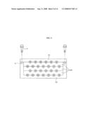
[0004]As shown in FIG. 1, a storage device for battery modules in prior art includes a housing 1 having outer and inner walls 1a, 1b that divide housing 1 into a plurality of sections with inlets and outlets for intake and exhaust of cooling air and through-holes 5 that are arranged in a plurality of columns and rows in the outer and inner walls 1a, 1b and form cylindrical spaces for supporting battery modules 3.
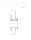
[0005]Shock-absorbing members 7 are placed to through-holes 5 so as to absorb the shock transmitted to battery modules 3. The shock-absorbing members have the same shape as outer and inner walls 1a, 1b. They have cylindrical protrusions 7a integrally formed therewith, which are inserted in the through-holes 5.
[0006]That is, the battery modules 3 received in the housing 1 are fitted in and supported by the cylindrical protrusions 7a of the shock-absorbing members 7 inserted in the through-holes 5.
[0007]Mounting brackets 9 are integrally formed with the housing 1.
[0008]The prior art storage device, however, has the following problems. First, since the outer walls 1a, inner walls 1b, and through-holes 5 are integrally formed in the storage device, a mold for manufacture of the storage device is complicated, resulting in increased costs and time for manufacturing and repairing the mold.
[0009]Next, it takes an excessively long time to fit the cylindrical protrusions 7a in the through-holes 5 formed through the outer and inner walls 1a, 1b when mounting the shock-absorbing members 7.
[0010]Lastly, it takes an excessive amount of time and effort to assemble the battery modules 3 with the housing 1 because the battery modules 3 are separately inserted one by one into the cylindrical protrusions 7a.
[0011]There is thus a need for improved storage devices for battery modules.
[0012]The information disclosed in this Background Art section is only for enhancement of understanding of the background of the invention and should not be taken as an acknowledgement or any form of suggestion that this information forms the prior art that is already known to a person skilled in the art.
SUMMARY OF THE INVENTION
[0013]The present invention has been made to provide storage devices for battery modules that can overcome the prior art problems. Embodiments of the present invention provide storage devices with a structure in which a housing receives the battery modules in a stack, thereby reducing processes required for assembly of battery modules, simplifying a mold for manufacturing a storage device for battery modules, and reducing the manufacturing cost.
[0014]A storage device for battery modules according to an embodiment of the invention includes a plurality of retaining members, receiving portions, and shock-absorbing members.
[0015]The retaining members are fastened to one another in a stack. The receiving portions form spaces divided by interfaces between the retaining members and arranged in a plurality of rows along the interfaces. The shock-absorbing members are mounted on the receiving portions.
[0016]It is understood that the term "vehicle" or "vehicular" or other similar term as used herein is inclusive of motor vehicles in general such as passenger automobiles including sports utility vehicles (SUV), buses, trucks, hybrid vehicles, various commercial vehicles, watercraft including a variety of boats and ships, aircraft, and the like. The present devices will be particularly useful with a wide variety of motor vehicles.
[0017]Other aspects of the invention are discussed infra.
BRIEF DESCRIPTION OF THE DRAWINGS
[0018]For better understanding of the nature and objects of the present invention, reference should be made to the following detailed description with the accompanying drawings, in which:
[0019]FIG. 1 is a perspective view of a prior art storage device for battery modules;
[0020]FIG. 2 is a cross-sectional view illustrating connection between inner/outer walls and a shock-absorbing member of FIG. 1;
[0021]FIG. 3 is a perspective view of a storage device for battery modules equipped with retaining members according to a first embodiment of the invention;
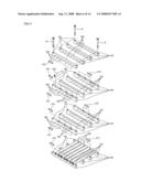
[0022]FIG. 4 is an exploded perspective view of FIG. 3;
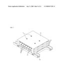
[0023]FIG. 5 is a perspective view of a storage device for battery modules equipped with a mounting plate and a cover plate;
[0024]FIG. 6 is an exploded perspective view of a storage device for battery modules equipped with retaining members according to a second embodiment of the invention;
[0025]FIG. 7 is a view illustrating a busbar plate for electric connection between battery modules;
[0026]FIGS. 8 to 10 are views illustrating fastening of retaining members stacked;
[0027]FIG. 11 is a view illustrating connection between stacked retaining members;
[0028]FIG. 12 is a view illustrating the configuration of a shock-absorbing member according to a first embodiment of the invention;
[0029]FIG. 13 is a view illustrating the configuration of a shock-absorbing member according to a second embodiment of the invention;
[0030]FIG. 14 is a view illustrating the configuration of a shock-absorbing member according to a third embodiment of the invention;
[0031]FIG. 15 is a view illustrating the configuration of a shock-absorbing member according to a fourth embodiment of the invention;
[0032]FIG. 16 is a view illustrating the configuration of a shock-absorbing member according to a fifth embodiment of the invention; and
[0033]FIG. 17 is a view illustrating the configuration of a shock-absorbing member according to a sixth embodiment of the invention.
DETAILED DESCRIPTION
[0034]Reference will now be made in detail to the embodiments of the present invention, examples of which are illustrated in the accompanying drawings, wherein like reference numerals refer to the like elements throughout. The embodiments are described below in order to explain the present invention by referring to the figures.
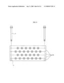
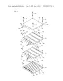
[0035]A storage device for battery modules according to an embodiment of the invention, as shown in FIGS. 3 and 4, includes several retaining members 100 that are fastened to one another in a stack, receiving portions 200 that form spaces divided up and down by interfaces 110 between the retaining members 100 and arranged in a plurality of lines along the interfaces 110, shock-absorbing members 300 of resin for attenuating shock that are mounted on the receiving portions 200, and several battery modules 400 that are surrounded by the shock-absorbing members 300 in the receiving portions 200 and electrically connected with each other.
[0036]Preferably, the retaining member 100 comprises upper and lower separate bodies 120 and intermediate separate bodies 140. Each of the upper and lower separate bodies 120 has a horizontal wall 122 horizontally formed in the arrangement direction of the battery modules 400, a pair of first outer walls 124 formed across the arrangement direction of the battery modules 400 at the left and right ends of the first horizontal wall 122, and first inner walls 126 disposed at regular intervals between the first outer walls 124. The above walls are integrally formed.
[0037]Each of the intermediate separate bodies 140, preferably, has a second horizontal wall 142 horizontally formed in the arrangement direction of the battery modules 400, a pair of second outer walls 144 formed across the arrangement direction of the battery modules 400 at the left and right ends of the second horizontal wall 142, corresponding to the first outer walls 124 of the upper and lower separate bodies 120 such that the upper and lower separate bodies 120 or the intermediate separate bodies 140 are stacked on one another, and second inner walls 146 disposed at regular intervals between the second outer walls 144, corresponding to the first inner walls 126 of the upper and lower separate bodies 120 such that the upper and lower separate bodies 120 or the intermediate separate bodies 140 are stacked on one another.
[0038]Fastening holes 128, 148 are formed at corners of the upper and lower separate bodies 120 and intermediate separate bodies 140 to connect them in stack with bolts B and nuts N.
[0039]Suitably, the receiving portions 200 are through-holes formed in a plurality of rows on interfaces 110 between the upper and lower separate bodies 120 and the intermediate separate bodies 140, and interfaces 110 between the intermediate separate bodies 140.
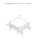
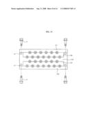
[0040]As shown in FIG. 5, a mounting plate 500 may preferably be fastened to the bottom of the lower separate body 120 and connected with a cover plate 510 covering the outside of the upper separate body 120.
[0041]As a result, stacked retaining members 100 can be firmly held by mounting the plate 500 and cover plate 510.
[0042]Bolts B are screwed in nuts N through the cover plate 510, fastening holes 128, 148, and mounting plate 500 in this order.
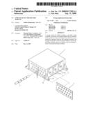
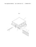
[0043]According to a second embodiment, as shown in FIG. 6, retaining members 100 may be formed of square bars, individual bodies 160 that are arranged at predetermined intervals across the arrangement direction of battery modules 400 and fastened to one another in stack.
[0044]Fastening holes 162 are formed at the corners of the separate bodies 160 to fasten them in stack with bolts B and nuts N.
[0045]Receiving portions 200 are through-holes formed in plurality of lines on interfaces 110 between the stacked separate bodies 160.
[0046]Specifically, in the first and second embodiments, the receiving portions 200 have the same shape as the external shape of the battery modules 400. For example, when the battery module 400 is in a shape of a cylinder, the receiving portion 200 is defined by semicircular grooves on interfaces 100 between the retaining members 100 and has a circular cross-section when the grooves are combined.
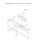
[0047]As shown in FIG. 7, grooves H connecting adjacent receiving portions 200 are formed on interfaces 110 between the receiving portions 200 at the left and right outermost sides of the retaining members 100. Busbar plates 410 are mounted on the grooves H so that the battery modules 400 placed in the receiving portions 200 can be electrically connected.
[0048]As shown in FIG. 8, when bolts B are screwed into nuts N through stacked retaining members 100 in this order, torsional deformation may be generated on the axes of bolts by torque applied to bolts B in screwing. The torsional deformation on the axes of bolts B decreases the fastening force by bolts B and nuts N. Thus, it is preferable to minimize the length of the bolts B within an acceptable range.
[0049]Therefore, as shown in FIGS. 9 and 10, it is preferable to reduce the fastening length of the bolts B in the stacked retaining members 100.
[0050]As shown in FIG. 9, that is, uppermost and lowermost retaining members 101, 102 are longer than intermediate retaining members 103. Further, both ends of the lowermost retaining members 102 are bent to cover both ends of the intermediate retaining members 103 and connected to the bottom of the uppermost retaining members 101 at both ends thereof.
[0051]In the above configuration, fastening holes 128, 148, 162 for bolts B are formed only at both end portions of uppermost and lowermost retaining members 101, 102.
[0052]Alternatively, as shown in FIG. 10, uppermost, lowermost, and middle retaining members 111,112, 113 are longer than intermediate retaining members 114 between the uppermost retaining members 111 and the middle retaining members 113, and the lowermost retaining members 112 and the middle retaining members 113.
[0053]Both ends of the middle retaining members 113 are bent to cover both ends of intermediate retaining members 114 and connected to the bottoms of uppermost and lowermost retaining members 111, 112 at both end portions thereof.
[0054]According to the above configuration, fastening holes 128, 148, 162 for bolts B are formed only at both end portions of the uppermost, lowermost and middle retaining members 111, 112, 113 in the retaining members 100.
[0055]Accordingly, when the retaining members 100 stacked in the structures shown in FIGS. 9 and 10 are fastened by bolts B and nuts N, the fastening length of bolts B is considerably reduced.
[0056]Further, when bolts B are reduced in length for fastening retaining members 100, torque applied to bolts B in fastening is used only to screw bolts B; therefore, it is possible to prevent reduction of fastening force due to torsional deformation at the axes of bolts B.
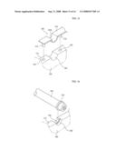
[0057]As shown in FIG. 11, grooves 100a and protrusions 100b for fitting are correspondingly formed on interfaces 110 between retaining members 100. That is, the groove 100a is formed at one of the two stacked retaining members 100 and protrusion 100b at the other.
[0058]The cross-section of the grooves 100a and protrusions 100b may be formed in various shapes, such as a square, wedge, and arc shapes, etc., as shown in FIG. 11.
[0059]Stacked retaining members 100 are maintained to be firmly connected by fitting the protrusions 100b in the grooves 100a until before they are fastened by bolts and nuts.
[0060]Suitably, shock-absorbing members 300 can be made of any shock-absorbing material, including rubber. The shock-absorbing members 300 absorb shock that is transmitted to battery modules 400 placed in receiving portions 200. The shock-absorbing members 300 can be placed on the entire surface or a part of receiving portions 200.
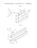
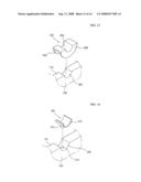
[0061]More Specifically, the shock-absorbing members 300 may be placed on receiving portions 200 in a variety of ways. In a first embodiment, as shown in FIG. 12, the shock-absorbing member 300 includes: a first shock-absorbing portion 302 with a plurality of smooth-recesses 302a each of which has the same shape of receiving portion 200 to cover interface 110; and a second shock-absorbing portion 304 that is integrally bent at 90° at both sides of the first shock-absorbing portion 302 to cover at least one side portion of retaining member 100.
[0062]In a second embodiment, as shown in FIG. 13, the shock-absorbing member 300 includes: a third shock-absorbing portion 306 that is recessed so as to individually cover receiving portion 200; and a fourth shock-absorbing portion 308 that is integrally bent at 90° at both sides of the third shock-absorbing portion 306 to cover at least one side portion of retaining member 100.
[0063]In a third embodiment, as shown in FIG. 14, the shock-absorbing member 300 includes: a fifth shock-absorbing portion 310 that is recessed so as to individually cover receiving portion 200; and a first fitting pin 312 that integrally protrudes from the bottom of the fifth shock-absorbing portion 310 and is fitted in a first insertion hole 210 formed in the receiving portion 200.
[0064]In a fourth embodiment, as shown in FIG. 15, the shock-absorbing member 300 includes: a sixth shock-absorbing portion 314 that has a smooth recess 314a having the same shape of receiving portion 200 and covers interface 110 near receiving portion 200; and second fitting pins 316 that integrally protrude from the bottom of the sixth shock-absorbing portion 314 at both sides thereof and are fitted in second insertion holes 220 formed in retaining member 100 near the receiving portion 200.
[0065]In a fifth embodiment, as shown in FIG. 16, the shock-absorbing member 300 is an O-ring 318 that is provided around battery module 400 and fitted in a first groove 230 formed in receiving portion 200 in a longitudinal direction thereof.
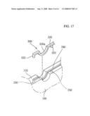
[0066]In a sixth embodiment, as shown in FIG. 17, the shock-absorbing member 300 includes: a band-shaped member 320 with a curved portion 320a, which is fitted in a second groove 240 recessed in and near receiving portion 200; and third fitting pins 322 that integrally protrude from the bottom of the band-shaped member 320 at both sides thereof and are fitted in third insertion grooves 250 formed in the second groove 240.
[0067]The second groove 240 has a polygonal cross-section and the band-shaped member 320 has a circular or polygonal cross-section. It is preferable that the band-shaped member 320 protrudes slightly above the second groove 240.
[0068]The above-described storage devices for battery modules can be assembled, for example, by the following process.
[0069]First, retaining member 100 is mounted on mounting plate 500 and then shock-absorbing members 300 are mounted on receiving portions 200 of retaining members 100. Subsequently, battery modules 400 are mounted on shock-absorbing members 300.
[0070]By repeating the above process, retaining members 100 are stacked on one another and then cover plate 510 is mounted on retaining members 100. Finally, bolts B are inserted into fastening holes 128, 148, 162 and then fixed to the bottom of mounting plate 500 by nuts (not shown).
[0071]As described above, since the present storage devices have a stack of a plurality of retaining members, a mold for manufacturing the storage device can be simpler in its structure and it is thus possible to reduce the costs for manufacturing and repairing the mold and the assembly time of the battery modules.
[0072]Also since the present storage devices simply place battery modules on receiving portions, unlike prior art storage devices in which battery modules are inserted into and fixed in receiving portions, it is possible to improve work efficiency and considerably reduce assembly time of the battery modules accordingly.
[0073]Furthermore, since shock-absorbing members are simply placed on the retaining members, it is possible to significantly improve work efficiency as well as reduce the assembly time of the shock-absorbing members.
[0074]Although the preferred embodiments of the present invention have been disclosed for illustrative purposes, those skilled in the art will appreciate that various modifications, additions and substitutions are possible, without departing from the scope and spirit of the invention as disclosed in the accompanying claims.
User Contributions:
comments("1"); ?> comment_form("1"); ?>Inventors list |
Agents list |
Assignees list |
List by place |
Classification tree browser |
Top 100 Inventors |
Top 100 Agents |
Top 100 Assignees |
Usenet FAQ Index |
Documents |
Other FAQs |
User Contributions:
Comment about this patent or add new information about this topic:
| People who visited this patent also read: | |
| Patent application number | Title |
|---|---|
| 20170092577 | Memory Device Interconnects and Method of Manufacture |
| 20170092576 | CONTACTING NANO-IMPRINTED CROSS-POINT ARRAYS TO A SUBSTRATE |
| 20170092575 | HYBRID PITCH PACKAGE WITH ULTRA HIGH DENSITY INTERCONNECT CAPABILITY |
| 20170092574 | METHOD FOR MANUFACTURE A POWER ELECTRONIC SWITCHING DEVICE AND POWER ELECTRONIC SWITCHING DEVICE |
| 20170092573 | HYBRID PITCH PACKAGE WITH ULTRA HIGH DENSITY INTERCONNECT CAPABILITY |
Images included with this patent application:
 |  |
 |  |
 |  |
 |  |
 |  |
 |  |
 |  |
 |
| Similar patent applications: | |
| Date | Title |
|---|---|
| 2010-07-08 | Shell restraining device for an anti-armour weapon |
| 2011-12-22 | Protection device for memory module |
| 2009-09-17 | Storage device for a data carrier |
| 2010-09-09 | Storage device for infant feed |
| 2011-01-06 | Storage device for a data carrier |
| New patent applications in this class: | |
| Date | Title |
|---|---|
| 2018-01-25 | Reclosable battery package |
| 2014-06-19 | Packaging construction |
| 2014-02-27 | Transportation apparatus for electrochemical energy storage apparatuses |
| 2013-12-05 | Device for supplying an inlet line of a packing machine with flat packs contained internally of a cardboard box, and a cardboard box containing flat packs |
| 2013-03-14 | Battery holder and dispensing package |
| New patent applications from these inventors: | |
| Date | Title |
|---|---|
| 2011-06-09 | Primary coil raising type non-contact charging system with elevating-type primary coil |
| 2009-04-02 | Support structure for battery modules |
| 2009-01-15 | Cooling structure for high voltage electrical parts of hybrid electric vehicle |
| 2008-12-25 | Grommet for coupling battery modules |
| 2008-12-18 | Cooling structure for high voltage electrical parts of a hybrid electric vehicle |
| Top Inventors for class "Special receptacle or package" | |
| Rank | Inventor's name |
|---|---|
| 1 | Donald E. Weder |
| 2 | Brett R. Glass |
| 3 | Daniel Lee Bizzell |
| 4 | Andrea Biondi |
| 5 | Nicole E. Glass |