Patent application title: Remote switch actuator
Inventors:
Paul John Simon (Gleason, WI, US)
IPC8 Class: AH01H1700FI
USPC Class:
200331
Class name: Actuators auxiliary extension or remote
Publication date: 2008-08-28
Patent application number: 20080202908
e drill switch actuator assembly that will
connect the switch of the cordless drill to the handle of the torque
multiplying transmission device. The concept of this invention is used on
a power transmission device for connecting a standard cordless battery
operated drill to an ice auger. Ice augers are utilized by fisherman in
the winter to drill holes in ice on frozen lakes. To the best of my
knowledge there are no other patents that use a cable and lever assembly
to actuate a switch on a cordless drill.Claims:
1. A Remote Switch Actuator assembly consisting of a lever pivoting on a
handle bar clamped to a cable passing through a cable housing, a lever
pivoting on a drill handle bracket, then passing through a return spring
and clamped to a drill handle bracket.Description:
SUMMARY OF INVENTION
[0001]Provisional patent No. 60/900,706 was granted on Feb. 12, 2007 for the Arm Saver. The Arm Saver was submitted as a complete assembly. It is a torque amplifying transmission that is used between any cordless drill driver and any hand auger. Hand augers are used to drill holes in the ice for ice fishing. During the course of the patent search, a chain drive transmission for ice augers had already been patented. We wish to patent the remote drill switch actuator assembly. Drawings for this assembly were originally submitted with the provisional patent.
BRIEF DESCRIPTION OF ASSEMBLY DRAWINGS
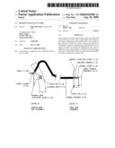
[0002]FIG. 1--Is a broken assembly view, which shows both drill end and handle bar end components of the Remote Switch Actuator assembly. Detail A shows the drill end assembly in the side view. Detail B shows handle bar end assembly in the top view.
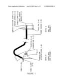
[0003]FIG. 2--Is an assembly view, which shows how the Remote Switch Actuator relates to the torque amplifying transmission, and how the transmission connects to the cordless drill/driver and auger. There are three views of the transmission to show the relation of the components. The cordless drill/driver and the auger are omitted in the top and front views for clarity.
DETAILED DESCRIPTION
[0004]FIG. 1 is the Remote Switch Actuator. The Remote Switch Actuator assembly is a device that will connect the switch of the cordless drill to the handle of the torque multiplying transmission device. There are two levers that are connected by a cable and a spring to return the system to a neutral position. Part numbers are taken from FIG. 1. One end of the cable (1-9) is mounted to a lever (1-8) on the u-shaped handle bar (1-7) that is connected to the torque multiplying device. The other end is connected to a lever (1-5) that pivots on a bracket (1-1) is clamped to the handle of the cordless drill to depress the switch of the drill. When lever (1-8) is released, spring (1-3) returns both levers (1-5 & 1-8) to the neutral position.
[0005]FIG. 2 is an assembly drawing showing how the transmission is positioned and gives reference to where the actuator assembly is located. The concept allows for the safe operation allowing the operator to control the unit both hands.
Claims:
1. A Remote Switch Actuator assembly consisting of a lever pivoting on a
handle bar clamped to a cable passing through a cable housing, a lever
pivoting on a drill handle bracket, then passing through a return spring
and clamped to a drill handle bracket.Description:
SUMMARY OF INVENTION
[0001]Provisional patent No. 60/900,706 was granted on Feb. 12, 2007 for the Arm Saver. The Arm Saver was submitted as a complete assembly. It is a torque amplifying transmission that is used between any cordless drill driver and any hand auger. Hand augers are used to drill holes in the ice for ice fishing. During the course of the patent search, a chain drive transmission for ice augers had already been patented. We wish to patent the remote drill switch actuator assembly. Drawings for this assembly were originally submitted with the provisional patent.
BRIEF DESCRIPTION OF ASSEMBLY DRAWINGS
[0002]FIG. 1--Is a broken assembly view, which shows both drill end and handle bar end components of the Remote Switch Actuator assembly. Detail A shows the drill end assembly in the side view. Detail B shows handle bar end assembly in the top view.
[0003]FIG. 2--Is an assembly view, which shows how the Remote Switch Actuator relates to the torque amplifying transmission, and how the transmission connects to the cordless drill/driver and auger. There are three views of the transmission to show the relation of the components. The cordless drill/driver and the auger are omitted in the top and front views for clarity.
DETAILED DESCRIPTION
[0004]FIG. 1 is the Remote Switch Actuator. The Remote Switch Actuator assembly is a device that will connect the switch of the cordless drill to the handle of the torque multiplying transmission device. There are two levers that are connected by a cable and a spring to return the system to a neutral position. Part numbers are taken from FIG. 1. One end of the cable (1-9) is mounted to a lever (1-8) on the u-shaped handle bar (1-7) that is connected to the torque multiplying device. The other end is connected to a lever (1-5) that pivots on a bracket (1-1) is clamped to the handle of the cordless drill to depress the switch of the drill. When lever (1-8) is released, spring (1-3) returns both levers (1-5 & 1-8) to the neutral position.
[0005]FIG. 2 is an assembly drawing showing how the transmission is positioned and gives reference to where the actuator assembly is located. The concept allows for the safe operation allowing the operator to control the unit both hands.
User Contributions:
Comment about this patent or add new information about this topic:
| People who visited this patent also read: | |
| Patent application number | Title |
|---|---|
| 20090298617 | GOLF BALL MATERIAL AND GOLF BALL |
| 20090298616 | GOLF BALL MATERIAL, GOLF BALL AND METHOD FOR PREPARING GOLF BALL MATERIAL |
| 20090298615 | FORGED IRON HEAD AND GOLF CLUB HAVING THE SAME |
| 20090298614 | RELATIVE POSITION BETWEEN CENTER OF GRAVITY AND HIT CENTER IN A GOLF CLUB |
| 20090298613 | Golf Club Head with Sound Tuning |
Images included with this patent application:
 |  |
 |  |
| Similar patent applications: | |
| Date | Title |
|---|---|
| 2009-12-24 | Dome switch with integral actuator |
| 2010-10-21 | Power seat switch to prevent simultaneous activation |
| 2012-04-26 | Push-on switch having improved actuator |
| 2012-11-01 | Power seat switch to present simultaneous activation |
| 2008-12-25 | High voltage switch configuration |
| New patent applications in this class: | |
| Date | Title |
|---|---|
| 2018-01-25 | Electronic switching device |
| 2015-12-24 | Light switch extender |
| 2015-12-03 | Devices, systems, methods, and kits for remotely operating a switch |
| 2015-11-05 | Switch extension and method of installation |
| 2015-05-14 | Handle operating device for circuit breaker |
| Top Inventors for class "Electricity: circuit makers and breakers" | |
| Rank | Inventor's name |
|---|---|
| 1 | Chao Chen |
| 2 | Bo-An Chen |
| 3 | Kil Young Ahn |
| 4 | Jean-Christophe Villain |
| 5 | Chung Yuan Chen |