Patent application title: Torque Converter for Use When Drilling with a Rotating Drill Bit
Inventors:
Per Olav Haughom (Tonstad, NO)
Nils Reimers (Bjoa, NO)
IPC8 Class: AE21B1722FI
USPC Class:
175323
Class name: Boring or penetrating the earth with tool shaft detail helix or helically arranged structure
Publication date: 2008-08-28
Patent application number: 20080202816
e in drilling with a rotating drill bit, the
purpose of the torque converter being to absorb impacts and bring about
an axial movement of the drill bit when the torque exceeds a
predetermined value. For this purpose the torque converter is composed of
two cylindrical string parts connected through the bearing elements. The
string parts are connected to each other through helical elements in such
a way that relative rotation of the two cylindrical string parts brings
about axial movement, which unloads the drill bit.Claims:
1. A torque converter for use in drilling with a rotating drill bit, the
torque converter being composed of an upper cylindrical string part (11)
concentrically supported on a lower cylindrical string part (16),
characterized in that the string parts (11 and 16) are connected through
helical spring elements (12).
2. The torque converter as described in claim 1, characterized in that between the string parts (11 and 16) are placed guide elements (13 and 15) and a seal (14).Description:
[0001]This invention relates to a devise for use with a rotating drill
bit, in which the aim is to absorb impacts and provide axial movement of
the drill bit when, for a time, the torque exceeds a predetermined value.
[0002]Torque converters and dynamic dampers which have the purpose of dampening vibrations and limit the maximum torque in the drill string are known from the oil industry, among other things. In a drill string several thousand metres long, vibrations may occur due to the varying torque on the string. Such vibrations are most often caused by the drill bit hitting different rock formations, which involves that a varying load is applied to the drill string. Then, when the drill string is rotated by the torque from the drilling machine, great amounts of energy are stored, which are released when the drill bit suddenly breaks loose.
[0003]Uncontrolled release of energy leads to extreme stresses on the drill string and drill bit. Today's controllable drilling systems are provided with much electromechanical equipment, which may get damaged by extreme shocks and vibrations.
[0004]In the present invention the aim is to employ a device, which yields immediately and, by and by, seeks to pull the drill bit axially from the bottom whenever the torque exceeds a predetermined value.
[0005]Such a device is particularly well suited for modern drill bits with fixed cutters, in which industrially manufactured diamonds of high hardness are used, but in which the structure is brittle and sensitive to impacts.
[0006]Within the oil industry problems connected with overloading of the drill string are well known, and there has been worked continuously on different solutions to remedy the problems. In this connection, reference is made to the following patents. [0007]NO 315209 [0008]GB 5,083,623 [0009]U.S. Pat. No. 4,281,726 [0010]GP 065 601 A1 [0011]U.S. Pat. No. 4,443,206 [0012]WO 97/01693
[0013]In principle, the present invention has the same function as NO 315209, but the technical design is substantially different. In the present invention the axial movement is provided by means of a set of spring elements, whereas in NO 315209 the axial movement is achieved through a trapezoidally threaded connection and a separate spring package. In relation to the state of the art the object of the invention
[0014]is to provide a solution, which gives an immediate protective response and subsequently, by continued overload, contracts to reduce the axial load on the drill bit, so that it is freed. In relation to the state of the art, the invention has substantial advantages, while, at the same time, being simpler and more robust. Thereby the risk of breakdowns is reduced. In addition substantially lower costs for production and maintenance are achieved.
[0015]This is achieved in accordance with the invention by two cylindrical string parts being concentrically supported within each other and arranged for restricted axial and rotational relative movement relative to each other. The string parts are connected through a number of helical spring elements in such a way that relative rotation of the string parts leads to axial movement when the torque exceeds a given value.
[0016]This device is connected in the drill string immediately behind the main components of the bottom-hole string, for example a motor driven by drilling fluid, a data acquisition unit and a control system, or as an integral part of the bottom-hole assembly, when a rotating drill string is used.
[0017]The invention will now be explained in further detail in connection with the description of an exemplary embodiment and with reference to the appended drawings, in which:
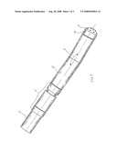
[0018]FIG. 1 shows the positioning of the invention relative to a drill string and mud motor;
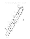
[0019]FIG. 2 shows the positioning of the invention relative to the bottom-hole assembly, in a rotating drill string;
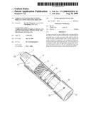
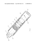
[0020]FIG. 3 shows the invention with a cylindrical string part partly in section.
[0021]In FIG. 1 numeral 1 indicates the invention fitted between a drill string 6 and a motor 2 driven by drilling fluid connected through the angular joint 3 to the drill bit 4 arranged with fixed shears 5.
[0022]In FIG. 2 is shown alternative positioning of the invention 1 inserted between a rotating drill string 6, a direction control unit 7 with guide pads 8 and a drill bit 4 with fixed shears 5.
[0023]An upper cylindrical string part 11 with threads 9 is supported concentrically on a lower cylindrical string part 16 through the bearing elements 13 and 15.
[0024]The string parts are connected to each other through helical elements 12 in such a way that relative rotation of the two cylindrical string parts brings about an axial movement.
[0025]By varying the thickness, helical pitch and materials of the spring elements 12 the torque 18 giving the desired axial movement, is determined.
[0026]Through the upper and lower string parts there is a through hole 10. The sealing element 14 seals against internal over-pressure.
Claims:
1. A torque converter for use in drilling with a rotating drill bit, the
torque converter being composed of an upper cylindrical string part (11)
concentrically supported on a lower cylindrical string part (16),
characterized in that the string parts (11 and 16) are connected through
helical spring elements (12).
2. The torque converter as described in claim 1, characterized in that between the string parts (11 and 16) are placed guide elements (13 and 15) and a seal (14).
Description:
[0001]This invention relates to a devise for use with a rotating drill
bit, in which the aim is to absorb impacts and provide axial movement of
the drill bit when, for a time, the torque exceeds a predetermined value.
[0002]Torque converters and dynamic dampers which have the purpose of dampening vibrations and limit the maximum torque in the drill string are known from the oil industry, among other things. In a drill string several thousand metres long, vibrations may occur due to the varying torque on the string. Such vibrations are most often caused by the drill bit hitting different rock formations, which involves that a varying load is applied to the drill string. Then, when the drill string is rotated by the torque from the drilling machine, great amounts of energy are stored, which are released when the drill bit suddenly breaks loose.
[0003]Uncontrolled release of energy leads to extreme stresses on the drill string and drill bit. Today's controllable drilling systems are provided with much electromechanical equipment, which may get damaged by extreme shocks and vibrations.
[0004]In the present invention the aim is to employ a device, which yields immediately and, by and by, seeks to pull the drill bit axially from the bottom whenever the torque exceeds a predetermined value.
[0005]Such a device is particularly well suited for modern drill bits with fixed cutters, in which industrially manufactured diamonds of high hardness are used, but in which the structure is brittle and sensitive to impacts.
[0006]Within the oil industry problems connected with overloading of the drill string are well known, and there has been worked continuously on different solutions to remedy the problems. In this connection, reference is made to the following patents. [0007]NO 315209 [0008]GB 5,083,623 [0009]U.S. Pat. No. 4,281,726 [0010]GP 065 601 A1 [0011]U.S. Pat. No. 4,443,206 [0012]WO 97/01693
[0013]In principle, the present invention has the same function as NO 315209, but the technical design is substantially different. In the present invention the axial movement is provided by means of a set of spring elements, whereas in NO 315209 the axial movement is achieved through a trapezoidally threaded connection and a separate spring package. In relation to the state of the art the object of the invention
[0014]is to provide a solution, which gives an immediate protective response and subsequently, by continued overload, contracts to reduce the axial load on the drill bit, so that it is freed. In relation to the state of the art, the invention has substantial advantages, while, at the same time, being simpler and more robust. Thereby the risk of breakdowns is reduced. In addition substantially lower costs for production and maintenance are achieved.
[0015]This is achieved in accordance with the invention by two cylindrical string parts being concentrically supported within each other and arranged for restricted axial and rotational relative movement relative to each other. The string parts are connected through a number of helical spring elements in such a way that relative rotation of the string parts leads to axial movement when the torque exceeds a given value.
[0016]This device is connected in the drill string immediately behind the main components of the bottom-hole string, for example a motor driven by drilling fluid, a data acquisition unit and a control system, or as an integral part of the bottom-hole assembly, when a rotating drill string is used.
[0017]The invention will now be explained in further detail in connection with the description of an exemplary embodiment and with reference to the appended drawings, in which:
[0018]FIG. 1 shows the positioning of the invention relative to a drill string and mud motor;
[0019]FIG. 2 shows the positioning of the invention relative to the bottom-hole assembly, in a rotating drill string;
[0020]FIG. 3 shows the invention with a cylindrical string part partly in section.
[0021]In FIG. 1 numeral 1 indicates the invention fitted between a drill string 6 and a motor 2 driven by drilling fluid connected through the angular joint 3 to the drill bit 4 arranged with fixed shears 5.
[0022]In FIG. 2 is shown alternative positioning of the invention 1 inserted between a rotating drill string 6, a direction control unit 7 with guide pads 8 and a drill bit 4 with fixed shears 5.
[0023]An upper cylindrical string part 11 with threads 9 is supported concentrically on a lower cylindrical string part 16 through the bearing elements 13 and 15.
[0024]The string parts are connected to each other through helical elements 12 in such a way that relative rotation of the two cylindrical string parts brings about an axial movement.
[0025]By varying the thickness, helical pitch and materials of the spring elements 12 the torque 18 giving the desired axial movement, is determined.
[0026]Through the upper and lower string parts there is a through hole 10. The sealing element 14 seals against internal over-pressure.
User Contributions:
Comment about this patent or add new information about this topic:
Images included with this patent application:
 |  |
 |  |
| Similar patent applications: | |
| Date | Title |
|---|---|
| 2012-07-26 | Drilling fluid recovery when drilling under an obstacle or water body |
| 2010-12-16 | Methods of drilling with a downhole drilling machine |
| 2012-07-12 | Boring tool tracking fundamentally based on drill string length, pitch and roll |
| 2012-08-30 | Pulsed electric rock drilling apparatus with non-rotating bit and directional control |
| 2010-12-30 | Drill packer member, drill pipe, and corresponding drill pipe string |
| New patent applications in this class: | |
| Date | Title |
|---|---|
| 2014-04-17 | Drill string components having multiple-thread joints |
| 2013-01-17 | Post hole digger |
| 2011-08-25 | Auger boring machine having spoils ejector |
| 2011-06-30 | drill string element with instruments |
| 2008-11-06 | Mounting system for a fiber optic cable at a downhole tool |
| New patent applications from these inventors: | |
| Date | Title |
|---|---|
| 2014-10-16 | Device for activation of gripping jaws in continuously rotating torque tongs for use under pulling and opening of threaded connections |
| 2013-08-15 | Pump positioned at a drill bit |
| 2013-06-13 | Apparatus for directional control of a drilling tool |
| 2012-09-13 | Method and device for reducing friction between helical members of a downhole damper |
| 2012-02-23 | Pump piston device |
| Top Inventors for class "Boring or penetrating the earth" | |
| Rank | Inventor's name |
|---|---|
| 1 | David R. Hall |
| 2 | Anthony A. Digiovanni |
| 3 | Danny E. Scott |
| 4 | Youhe Zhang |
| 5 | Steven R. Radford |