Patent application title: Distributed Combined Junctional Transformer
Inventors:
Benjamin Kim (Mclean, VA, US)
IPC8 Class: AH04B714FI
USPC Class:
370315
Class name: Multiplex communications communication over free space repeater
Publication date: 2016-01-28
Patent application number: 20160028468
Abstract:
The Distributed Combined Junctional Transformer (abbreviated in this
document as repeater station) provides a system to take any input signal
in any frequency and using any modulation and multiplexing schemes,
convert it to the desired format and frequency and subsequently
retransmits the signal. In accordance with an embodiment of the
invention, a repeater station comprises: an input section capable of
receiving the input signal generated by any source device in radio,
microwave, infrared, visible or ultraviolet spectrums; a downconversion
section translating the input signal to a baseband signal if required; a
baseband processing section that interprets the information of the input
signal, converts the signal to the desired format and controls the other
sections; an upconversion section which translates the baseband frequency
output signal to the desired carrier output frequency if required; and an
output section which transmits the output signal.Claims:
1. The repeater station provides a system to take any input signal in any
frequency and using any modulation and multiplexing schemes, convert it
to the desired format and frequency and subsequently retransmits the
signal comprising: an input section receiving the input signal generated
by any source device in radio, microwave, infrared, visible or
ultraviolet spectrums; a downconversion section if required translating
the said input signal to a baseband frequency capable of conversion into
the digital domain; a baseband processing section that can perform the
functions of signal conversions, filtering, storage as required, digital
signal processing, configuration management, reference signal generation,
as well as telemetry and commanding functions; a upconversion section if
required translating the baseband frequency signal to the desired carrier
output frequency; and an output section transmitting the output signal to
any receiving device in radio, microwave, infrared, visible or
ultraviolet spectrums.
2. The said repeater station from claim in which the said input section further comprising: tracking input antennas either mechanically or electrically ranging in polarizations and frequency responses that can include multiple antennas that can be spatially distributed in order to maximize antenna gain in the upper radio or microwave spectrum; lengthy whip input antennas which may be formulated into a helical pattern can be utilized in the lower radio spectrum; an input device such as an array of filtered photodiodes, which may be attached to a mechanism to provide pivoted support that allows the rotation to provide tracking capabilities, that are connected directly to said baseband processing section from claim in the optical spectrum in the infrared and ultraviolet spectrums; an assembly consists of an array of focusing optics such as a telescope connected to a prism to separate the wavelengths that are positioned around the prism is an array of wavelength specific filters and photodiodes, which may be attached to a mechanism to provide pivoted support that allows the rotation to provide tracking capabilities, that are connected directly to said baseband processing section from claim in the optical spectrum; and said input antennas can be connected to a test coupler for measurement purposes.
3. The said repeater station from claim in which the said downconversion section further comprising: an amplifying stage controlled by the said baseband processor section from claim 1; a dual-stage mixer encompassing independent local oscillator signals generated from a source such as a phase locked loop which is given a reference clock signal from the said baseband processor section from claim 1; and a switching matrix located prior to the said amplifying stages between said amplifying stage and said mixers, between said mixer stages, as well as after said mixer stages all controlled by the said baseband processor section from claim 1.
4. The said repeater station from claim 1 in which the said upconversion section further comprising: an analog filtering section comprising a bank of filters controlled by the signal routing by said baseband processor section from claim 1; an amplifying stage controlled by the said baseband processor section from claim 1; a dual-stage mixer encompassing independent local oscillator signals generated from a source such as a phase locked loop which is given a reference clock signal from the said baseband processor section from claim 1; and a switching matrix located prior to the said analog filtering section, between said analog filtering section said amplifying stage between said amplifying stage and said mixes, between said mixer stages, as after said mixer stages all controlled by the said baseband processor section from claim 1.
5. The said repeater station from claim 1 in which the said output section further comprising: tracking output antennas either mechanically or electrically ranging in polarizations and frequency responses that can include multiple antennas that can be spatially distributed in order to maximize antenna gain in the upper radio or microwave spectrum; lengthy whip output antennas which may be formulated into a helical pattern can be utilized in the lower radio spectrum; an output device such as an array of filtered light emitting diodes or laser diodes, which may be attached to a focusing mechanism and a mechanism to provide pivoted support that allows the rotation to provide tracking capabilities, that are connected directly to said baseband processing section from claim in the optical spectrum in the infrared, optical and ultraviolet spectrums; and said output antennas can be connected to a test coupler for measurement purposes.
6. The said repeater station from claim 1 in which the said baseband processing section further comprising: a global navigation satellite system receiver to provide location and timing inputs; a command and telemetry processing section that can communicate external to the said repeater station to provide status and receive commands as well as communicate within the said repeater station to the various sections comprising said downconversion section of claim 1, said upconverstion section of claim 1, said output section of claim 1, the said global navigation satellite system receiver, an analog-to-digital converter section, a digital-to-analog converter section, and a re-programmable logic section; said analog-to-digital converter section encompassing a programmable sampling rate controlled by the said command and telemetry processing section; said re-programmable logic section as to facilitate the filtering, sampling required to decode any modulation scheme including frequency, amplitude and phase, and interpret the framing and then reframe, multiplex and modulate to the desired formatting and if required can store the received or translated data for archival purposes in the digital domain; and said digital-to-analog converter section encompassing a programmable sampling rate controlled by the said command and telemetry processing section;
Description:
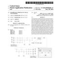
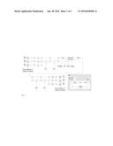
[0001] The Distributed Combined Junctional Transformer (abbreviated in
this document as repeater station) provides a system to take any input
signal in any frequency and using any modulation and multiplexing
schemes, convert it to the desired format and frequency and subsequently
retransmits the signal. In accordance with an embodiment of the
invention, a repeater station comprises: for the radio and microwave
input (see the next paragraph for infrared, visible or ultraviolet
spectrum input), a group of selectable receive antennas which are
specified for both frequency and polarization connected to a test coupler
(optional) and then input circulator to prevent input saturation
(optional) and then to a low-noise amplifier (LNA) and wide bandpass
filter; a dual-stage mixers with the local oscillator signal being
supplied from a reference such as a phase-locked loop (PLL) which is fed
by the baseband processor to make frequency translation from the carrier
frequency to baseband possible for any frequency and the first stage
being capable of bypass which takes the signal down to broadband
frequencies; an analog-to-digital converter (ADC) with a programmable
sampling rate controlled by the baseband processor; a baseband processor
with an input clock reference such as an oven controlled crystal
oscillator (OCXO) and a Global Navigation Satellite System (GNSS) input
such as a US NAVSTAR GPS/Russian Glonass/EU Galileo/Chinese Beidou or
Compass/Indian IRNSS/Japanese QZSS receiver or even a augmentation system
based receiver such as the US WAAS/EU EGNOS/Japanese MSAS/Indian GAGAN
receiver that will first complete the digital filtering for the desired
input signal including multiplexing if required and then demodulate and
interpret the framing with the possibility of data storage (optional) and
then reframe and modulate to the desired formatting; a digital-to-analog
converter (DAC) also with a programmable sampling rate controlled by the
baseband processor; another dual-stage mixers with PLL; a wide bandpass
filter; an amplification stage utilizing wideband devices such as
traveling wave tube amplifiers (TWTA) or solid state power amplifier
(SSPA); an output test coupler (optional) connected to a transmit antenna
for the correct frequency and polarization.
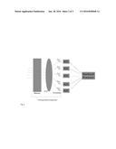
[0002] In the presence of an infrared, visible or ultraviolet spectrum input signal, a series of wavelength dependent device such as a photodiode mounted on a tracking gimbal connected directly to the analog to digital converters instead of the receive antennas, LNAs, filters, and mixers. Also for an infrared, visible or ultraviolet transmission, the DAC is connected to the optical output device such as a light-emitting diode (LED) or laser diode which may transmit through a series of focusing devices such as mirrors mounted on a tracking gimbal.
TECHNICAL FIELD
[0003] The repeater station relates to any source device that is capable of generating or receiving a signal in either radio, microwave, infrared, visible or ultraviolet spectrums, reads the information, formats the translation and transmits the signal in the desired format and frequency to the desired recipient device. An example of the connectivity would be between a line-of-sight (LOS) VHF handheld radio using frequency modulation without framing in a vertical polarization converted to a Ka-band satellite uplink using Generic Stream Encapsulation for the framing with low-density parity-check code error checking with an 8PSK modulation in a left-hand circular polarization.
BACKGROUND OF THE INVENTION
[0004] Wireless service providers are under constant pressure by their customers to improve and expand coverage while decreasing the cost of service. This conflicts with the pressure from investors and stockholders to increase earnings and decrease expenses. In addition, local zoning and regulatory pressures often limit or preclude placement of base station sites in the optimum locations. Additionally, as technology progresses, wireless service providers and their suppliers are constantly having to spend large amounts of capital to upgrade existing base stations to be able to support new modulation schemes and released frequency spectrums.
[0005] This invention incorporates several concepts to create a "future-proof" repeater that significantly reduces the costs for a repeater site. It will allow for wireless service providers to launch next generation networks utilizing only software changes. In one embodiment of the invention, the only equipment to install is the repeater itself and the primary power cables. In addition, the repeater station in this invention contains support software and equipment to allow the repeater station to perform antenna alignment and gain set up with only minimal support from technical personnel. Changes to the modulation scheme, frequency bands, power levels, regulatory requirements, or any other parameter can be satisfied solely by software changes remotely. This invention, while potentially increasing the one-time hardware repeater costs, dramatically results in a reduction of the total cost of a repeater site as then tower service providers can automatically support all the wireless service providers and incremental as well as generational changes without hardware changes or site-visits.
[0006] This invention can also be used to provide in a vast array of applications on any platform whether it be stationary or mobile (to encompass marine, auto, airborne, and space-based platforms) to provide interconnectivity where previously not possible. Additionally, being that any transmitted source of data is a potential input, this invention can provide functionality that is not currently available to the mass market to include technologies that both currently exist such as providing traditional 2.4 GHz WiFi from cellular base stations to technologies that do not have existing market utilization or products such as 96 GHz EHF microwave links on satellites.
BRIEF SUMMARY OF THE INVENTION
[0007] Accordingly, the present invention provides a translation of any input signal in any format to any output signal in any format. The invention definition including the features is described in the appended claims.
BRIEF DESCRIPTION OF THE FIGURES (DRAWINGS)
[0008] FIG. 1 is a block diagram of the system from receive (RX) antennas to transmit (TX) antennas
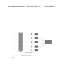
[0009] FIG. 2 is a substitute block diagram of the system for the RX portion in the infrared, visible and ultraviolet spectrums
[0010] FIG. 3 is a substitute block diagram of the system for the TX portion in the infrared, visible and ultraviolet spectrums
User Contributions:
Comment about this patent or add new information about this topic:
Images included with this patent application:
 |  |
 |  |
| Similar patent applications: | |
| Date | Title |
|---|---|
| 2016-02-18 | Distributed bi-directional flow control in wireless mesh networks |
| 2016-02-25 | Method and apparatus for distributed compositional control of end-to-end media in ip networks |
| 2015-10-15 | Distribution of synchronization packets over wifi transport links |
| 2016-03-03 | Distributed input/output architecture for network functions virtualization |
| 2015-11-12 | Distributed mobility anchoring for wireless networks |
| New patent applications in this class: | |
| Date | Title |
|---|---|
| 2022-05-05 | Method for relaying unstructured traffic, and relay ue |
| 2022-05-05 | Network routing system, method, and computer program product |
| 2022-05-05 | Relay node and method for encapsulating a packet based on tunneling protocol |
| 2019-05-16 | Wireless communication system control of carrier aggregation for a wireless relay |
| 2019-05-16 | Method of extending rf signals in a wireless control system |
| Top Inventors for class "Multiplex communications" | |
| Rank | Inventor's name |
|---|---|
| 1 | Peter Gaal |
| 2 | Wanshi Chen |
| 3 | Tao Luo |
| 4 | Hanbyul Seo |
| 5 | Jae Hoon Chung |