Patent application title: HEAT EXCHANGER TUBE
Inventors:
Kyouhei Takimoto (Saitama, JP)
Takashi Kaneda (Saitama, JP)
IPC8 Class: AF28F140FI
USPC Class:
165177
Class name: Heat exchange tubular structure
Publication date: 2015-10-22
Patent application number: 20150300755
Abstract:
A heat exchanger tube which, while preventing the increased flow
resistance when the medium flows, can enhance the heat radiation
performance, is provided. The heat exchanger tube 1 includes an upstream
side linear flow path part 4A and a downstream side linear flow path part
4B connecting an entrance part 2 and exist part 3 to each other and
enabling the medium to flow therethrough, wherein at least one of the
upstream side flow path part 4A and downstream side flow path part 4B
includes, within the flow path of the medium, wave-shaped portions 5a,
5b, 5c, 5d extending in the longitudinal direction of the tube and
continuing with each other for guiding the medium.Claims:
1. A heat exchanger tube comprising: an entrance part for a medium; an
exit part for the medium; and an upstream side linear flow path part and
a downstream side linear flow path part connecting the entrance and exist
parts to each other and enabling the medium to flow therethrough,
wherein: at least one of the upstream side and downstream side flow path
parts includes, within the flow path of the medium, wave-shaped portions
extending in the longitudinal direction of the tube and continuing with
each other for guiding the medium; and the medium flows flow path parts
defined by the wave-shaped portions and located next to each other.
2. The heat exchanger tube according to claim 1, wherein the wave-shaped portions are projecting portions projecting inwardly of the tube.
3. The heat exchanger tube according to claim 2, wherein the wave-shaped projecting portions are inner fins.
4. The heat exchanger tube according to claim 1, wherein the entrance and exit parts are arranged on one end side of the tube, the tube includes, on the other end side thereof, a U-turn flow path part for connecting the upstream side and downstream side linear flow path parts to each other, and the U-turn path part includes an arc-shaped projecting portion projecting inwardly of the tube and continuing with the wave-shaped portion formed at least in one of the upstream side and downstream side linear flow path parts.
5. The heat exchanger tube according to claim 1, wherein the wave-shaped portion is constituted of multiple wave-shaped portions arranged in the thickness direction of the tube.
6. The heat exchanger tube according to claim 5, wherein a pair of the wave-shaped portions are so arranged as to be situated at the same position and such wave-shaped portions are opposed to each other continuously.
7. The heat exchanger tube according to claim 5, wherein only the partial sections of the paired wave-shaped portions cross each other and only such partial sections are opposed to each other.
8. The heat exchanger tube according to claim 5, wherein the paired wave-shaped portions are parallel arranged alternately.
9. The heat exchanger tube according to claim 4, wherein the end of a U-turn portion of the U-turn flow path part straddles inwardly the end of a partition part for separating the upstream side and downstream side flow path parts from each other.
10. The heat exchanger tube according to claim 1, wherein: the medium flowing within the tube is cooling water; and the heat exchanger tube is the tube of a water-cooling type charge air cooler for allowing the cooling water and compressed air flowing outside the tube to exchange heat with each other to thereby cool the compressed air.
11. The heat exchanger tube according to claim 5, wherein phases corresponding to shapes of the wave-shaped portions, located next to each other in the thickness direction of the tube, are offset from each other.
12. The heat exchanger tube according to claim 5, wherein phases corresponding to shapes of the wave-shaped portions, located next to each other in the thickness direction of the tube, have an opposite-phase relation with each other.
Description:
TECHNICAL FIELD
[0001] The invention relates to a heat exchanger tube.
BACKGROUND ART
[0002] Conventionally, there are known heat exchanger tubes which are disclosed in the patent documents 1 and 2.
[0003] Such conventional heat exchanger tubes respectively include a tube member the two outsides of which are formed of beads except for the entrance and exit parts thereof and the central portion of which has a partition bead and a flow path enabling a medium to flow in a U-like manner therethrough. The path has a large number of projecting portions projecting inward in order to stir the flowing medium for enhancing heat radiation performance. Two tube plates having such structure are assembled together to form the tube.
RELATED DOCUMENTS
Patent Documents
[0004] Patent Document 1: JP-A-H02-169127
[0005] Patent Document 2: WO 1983-04090 A1
SUMMARY OF THE INVENTION
Problems that the Invention is to Solve
[0006] When a large number of projecting portions are arranged within the flow path, although the heat radiation performance is enhanced, the flow resistance increases.
[0007] The invention aims at solving the above problem and thus it is an object of the invention to provide a heat exchanger tube which, while preventing the increased flow resistance when the medium flows, can enhance the heat radiation performance.
Means for Solving the Problems
[0008] In attaining the above object, the heat exchanger tube of the invention comprises: an entrance part for a medium; an exit part for the medium; and, an upstream side linear flow path part and a downstream side linear flow path part connecting the entrance and exist parts to each other and enabling the medium to flow therethrough, wherein at least one of the upstream and downstream side flow path parts includes, in the flow path of the medium, wave-shaped portions extending in the longitudinal direction of the tube and continuing with each other for guiding the medium.
Advantages of the Invention
[0009] According to the heat exchanger tube of the invention, due to provision of the wave-shaped portions, when the medium flows, the flow resistance can be restricted and the stirring of the medium by the wave-shaped portions can enhance the heat radiation performance.
BRIEF DESCRIPTION OF THE DRAWINGS
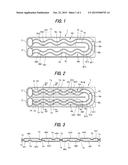
[0010] FIG. 1 is a section view of a heat exchanger tube according to an embodiment 1 of the invention.
[0011] FIG. 2 is a section view of a heat exchanger tube according to an embodiment 2 of the invention.
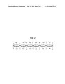
[0012] FIG. 3 is section view of the heat exchanger tube according to the embodiment 2, taken along the S3-S3 line of FIG. 2.
[0013] FIG. 4 is section view of the heat exchanger tube according to the embodiment 2, taken along the S4-S4 line of FIG. 2.
MODES FOR CARRYING OUT THE INVENTION
[0014] Description is given below specifically of the mode for carrying out the invention with reference to the embodiments shown in the drawings.
Embodiment 1
[0015] Firstly, description is given of the whole structure of the heat exchanger tube of the embodiment 1.
[0016] As shown in FIG. 1, the heat exchanger tube 1 of the embodiment 1 is used in a water-cooling type charge air cooler for cooling the compressed air of a charger (turbocharger or supercharger) attached to an internal combustion engine.
[0017] The heat exchanger tube 1 is produced by assembling together two half-divided tube plates.
[0018] The tube 1 includes an outer peripheral rib portion 1a which projects inward in the thickness direction (height direction) thereof along the outer periphery thereof except for the entrance part 2 and exit part 3 thereof.
[0019] Also, the tube 1 includes a partition rib portion (corresponding to a partition portion) 1b formed at the central position in the width direction (vertical direction in FIG. 1) of the tube 1 and extending toward the longitudinal direction (horizontal direction in FIG. 1) of the tube from between the entrance part 2 and exist part 3 disposed on one end side of the tube 1. The rib portion 1b extends up to the vicinity of a U-turn flow path part 4C (which is described later) on the other end side of the tube 1. The rib portion 1b separates the tube 1 into two areas, that is, an upstream side linear flow path part 4A and a downstream side linear flow path part 4B.
[0020] The downstream side end of the upstream side linear flow path part 4A and the upstream side end of the downstream side linear flow path part 4b are allowed to communicate with each other on the other end side of the tube 1 by the U-turn flow path part 4C.
[0021] Meanwhile, the entrance part 2 and exit part 3 are arranged side by side in the width direction of the tube 1. A parallel circuit with the cooling water of the engine used as the medium or a portion of the cooling water of the engine introduced therein, or an independent circuit (for example, a cooling water circuit for a charger-air-cooler) different from the cooling water of the engine are allowed to enter and leave the entrance part 2 and exit part 3 through the penetration holes thereof. The entrance part 2 is connected to the upstream side end of the upstream side linear flow path part 4A continuously therewith, while the exit part 3 is connected to the downstream side end of the downstream side linear flow path part 4B continuously therewith.
[0022] The upstream side linear flow path part 4A includes three upstream side flow paths 4A1, 4A2 and 4A3 respectively between the outer peripheral rib portion 1a existing on the upper side of FIG. 1 and partition rib portion 1b. The upstream side flow paths 4A1, 4A2 and 4A3 respectively include wave-shaped multiple projecting sections 5a, 5b which project side by side inward in the thickness direction (on this side in FIG. 1) between the outer peripheral rib portion 1a and partition rib portion 1b and are wave-formed when viewed from above the thickness direction.
[0023] Similarly, the downstream side linear flow path part 4B includes three downstream side flow paths 4B1, 4B2 and 4B3 respectively between the outer peripheral rib portion 1a existing on the lower side of FIG. 1 and partition rib portion 1b. The downstream side flow paths 4B1, 4B2 and 4B3 respectively include wave-shaped multiple projecting portions 5c, 5d which project side by side inward in the thickness direction between the outer peripheral rib portion 1a and partition rib portion 1b and are wave-formed when viewed from above the thickness direction.
[0024] Here, the wave-shaped projecting portions 5a, 5b, 5c, 5d correspond to the wave-shaped portions of the invention.
[0025] On the other hand, the U-turn path part 4C includes multiple arc-shaped projecting portions 6a, 6b which are formed inside the outer peripheral rib portion 1a on the other end side of the tube 1, project inward in the thickness direction and are arc-shaped when viewed from above the thickness direction. Here, the curvature of the arc-shaped projecting portion 6a is set larger than that of the arc-shaped projecting portion 6b.
[0026] Therefore, in the U-turn path part 4C, between the outer peripheral rib portion 1a and the outside arc-shaped projecting portion 6a, between the outside arc-shaped projecting portion 6a and inside arc-shaped projecting portion 6b, and between the inside arc-shaped projecting portion 6b and the other end side end of the partition rib portion 1b, there are formed a total of three U-turn flow paths 4C1, 4C2 and 4C3 respectively. The curvatures of the U-turn flow paths 4C1, 4C2 and 4C3 are set such that the inflow direction and outflow direction of the medium can be changed 180° from each other.
[0027] In this case, the two ends of the outside arc-shaped projecting portion 6a respectively continue with the downstream side end of the wave-shaped projecting portion 5a and the upstream side end of the wave-shaped projecting portion 5d. This enables the medium to flow through the entrance part 2, outside upstream side flow path 4A1, outside U-turn flow path 4C1, outside downstream side flow path 4B1 and exit part 3.
[0028] Also, the two ends of the inside arc-shaped projecting portion 6b respectively continue with the downstream side end of the wave-shaped projecting portion 5b and the upstream side end of the wave-shaped projecting portion 5c. This enables the medium to flow through the entrance part 2, central upstream side flow path 4A2, central U-turn flow path 4C2, central downstream side flow path 4B2 and exit part 4, and also through the entrance part 2, inside upstream side flow path 4A3, inside U-turn flow path 4C3, outside downstream side flow path 4B3 and exit part 3.
[0029] Here, the upstream side end of the outside arc-shaped projecting portion 6a and the downstream side end of the wave-shaped projecting portion 5a, and the upstream side end of the inside arc-shaped projecting portion 6b and the downstream side end of the wave-shaped projecting portion 5b are connected to each other respectively by linear projecting portions 7a and 7b which are respectively extended by a specific distance toward upstream from the downstream side end of the partition rib portion 1b.
[0030] Although not shown, there is further prepared a third tube plate by molding. The third tube plate includes wave-shaped projecting portions and arc-shaped projecting portions having the shapes and positions of images reflected by mirrors which are so parallel arranged upwardly of FIG. 1 as to face FIG. 1.
[0031] Then, the tube plate having the shape of FIG. 1 and the third tube plate are assembled together. In this assembled state, the wave-shaped projecting portions, arc-shaped projecting portions and linear projecting portions of these tube plates are opposed to each other at the same positions.
[0032] In this state, the wave-shaped projecting portions, arc-shaped projecting portions, linear projecting portions, outer peripheral rib portions and partition rib portions of these tube plates are fixed together by brazing or the like, thereby providing the tube 1.
[0033] In the above-structured heat exchanger tube, the cooling water supplied from the entrance part 2 flows meandering through the three upstream side flow paths 4A1, 4A2 and 4A3 within the upstream side linear path portion 4A under the control of the wave-shaped projecting portions 5a, 5b, and flows into the U-turn flow path part 4C along the linear projecting portions 7a, 7b.
[0034] In the U-turn flow path part 4C, the flow direction of the cooling water is gradually changed 180° within the three arc-shaped U-turn flow paths 4C1, 4C2 and 4C 3 along the arc-shaped projecting portions 6a and 6b, thereby guiding the cooling water to the three downstream side flow paths 4B1, 4B2 and 4B3.
[0035] Thereafter, the medium advances meandering within the three wave-shaped downstream side flow paths 4B1, 4B2 and 4B3 under the control of the wave-shaped projecting portions 5c and 5d, and flows out from the exit part 3.
[0036] Thus, the cooling water, while being stirred as in conventional dimples or the like, flows within the tube. The wave-like meandering of the cooling water can restrict an increase in the flow resistance and can secure the heat radiation performance. Also, as described above, in the U-turn flow path part as well, the direction of the cooling water is gradually changed. This can reduce the possibility that the cooling water can strike strongly at the end of the tube and thus can be damaged by erosion.
[0037] Meanwhile, the high-temperature compressed air flowing outside the tube passes the tube exchanges its heat with the cooling water, whereby it is cooled. After fuel is blown into this air, the mixture thereof is combusted in the combustion room of the engine.
[0038] As described above, the heat exchanger tube of the embodiment 1 can provide the following effects.
[0039] That is, since the wave-shaped projecting portions 5a, 5b, 5c, 5d are formed in the upstream side and downstream side linear flow path parts 4A and 4B, the flow resistance when the cooling water flows can be restricted, and also since the cooling water flows along the wave-shaped projecting portions 5a, 5b, 5c, 5d, the heat radiation performance can be enhanced.
[0040] Since the tube 1 is manufactured by assembling together the two half-divided tube plates, the tube 1 can be manufactured easily and inexpensively.
[0041] Also, in this case, the wave-shaped projecting portions 5a, 5b, 5c, 5d of the two tube plates are arranged to provide the same positions and the wave-shaped projecting portions 5a, 5b, 5c, 5d are continuously opposed to each other, thereby enabling the cooling water to meander.
[0042] Also, the ends of the arc-shaped projecting portions 6a, 6b of the U-turn flow path part 4C are arranged to straddle the downstream side end of the partition rib part 1b, thereby enabling restriction of disturbance of the cooling water here. That is, the cooling water is enabled to flow smoothly between the linear flow path parts (between the upstream side and downstream side linear flow path parts 4A and 4B), whereby the flow resistance can be restricted.
Embodiment 2
[0043] FIG. 2 shows a heat exchanger tube 1 of an embodiment 2. In the heat exchanger tube 1 of the embodiment 2, there are prepared two tube plates having the same structure of the embodiment 1.
[0044] One tube plate is inverted and combined with the other to provide the tube 1.
[0045] In this case, the mirror-reflected third tube plate of the embodiment 1 is not used. Thus, the wave-shaped projecting portions 5a, 5b, 5c, 5d of the upstream side and downstream side linear flow path parts 4A, 4B and the arc-shaped projecting portions 6a, 6b respectively formed in the other tube are disposed as shown by broken lines in FIG. 2.
[0046] In this case, in the wave-shaped projecting portions 5a, 5b, 5c, 5d and linear projecting portions 7a, 7b of the two tube plates, only the partial sections thereof are opposed to each other, whereas the remaining sections are shifted from each other in the width direction of the tube 1. Meanwhile, the arc-shaped projecting portions 6a and 6b of the U-turn flow path part 4C are situated at the same positions and are continuously opposed to each other.
[0047] That is, the wave-shaped projecting portions 5a, 5b and wave-shaped projecting portions 5c, 5d, which are paired wave-shaped portions, are alternately arranged side by side. Thus, in the wave-shaped portions, only the partial sections of the wave-shaped projecting sections 5a, 5b constituted of the paired wave-shaped portions (or, the wave-shaped projecting portions 5c, 5d) cross each other, while only such partial sections are opposed to each other.
[0048] The remaining structures are similar to the embodiment 1.
[0049] FIG. 3 is a transverse section view taken along the S3-S3 line passing the above-mentioned mutually shifted sections, and FIG. 4 is a section view taken along the S4-S4 line passing the above-mentioned mutually opposed sections.
[0050] As can be understood from these section shapes, unlike the prior art using a large number of dimples, the cooling water is prevented from being stirred greatly.
[0051] In the heat exchanger tube 1 of the embodiment 2, since the stirring is easier than in the embodiment 1, the heat radiation performance is enhanced. In this case, the flow resistance increases slightly when compared with the embodiment 1.
[0052] However, since, as the two tube plates to be assembled, the same tube plate can be used, the tube 1 can be manufactured more inexpensively than the embodiment 1.
[0053] Although the invention has been discussed heretofore with reference to the above embodiments, the invention is not limited to these embodiments but can be changed in design or the like without departing from the subject matter thereof.
[0054] For example, in the embodiment 1, the wave-shaped projecting portions 5a, 5b are formed in both of the upstream side and downstream side linear flow path parts 4A and 4B. However, the portions may also be formed only in one of the two parts.
[0055] Also, the medium may also be guided using inner fins instead of the wave-shaped projecting portions 5a, 5b and arc-shaped projecting portions 6a, 6b. Use of the inner fins can enhance the setting freedom of the shape of the wave-shaped portions.
[0056] Also, the respective arc-shaped and wave-shaped projections are connected to each other by the linear projecting portions 7a and 7b extended by a specific distance toward upstream side from the downstream side end of the partition rib portion 2b. However, when, instead of the linear projecting portions 7a and 7b, wave-shaped projecting portions are used to assemble together two tube plates having the same shape, the tube 1 can be manufactured more inexpensively.
[0057] Although the heat exchanger tube of the invention is used in the water-cooled charge air cooler, this is not limitative but it can also be applied to other types of heat exchangers.
[0058] Here, the present application is based on JPA (JPA No. 2012-239052) filed on Dec. 30, 2012 and thus the whole thereof is used herein by citation. Also, all references cited herein are contained herein as a whole.
DESCRIPTION OF REFERENCE NUMERALS AND SIGNS
[0059] 1: tube (heat exchanger tube)
[0060] 1a: outer peripheral rib part
[0061] 1b: partition rib part (partition part)
[0062] 2: entrance part
[0063] 3: exit part
[0064] 4A: upstream side linear flow path part
[0065] 4B: downstream side linear flow path part
[0066] 4C: U-turn flow path part
[0067] 4A1, 4A2, 4A3: upstream side flow path
[0068] 4B1, 4B2, 4B3: downstream side flow path
[0069] 4C1, 4C2, 4C3: U-turn flow path
[0070] 5a, 5b, 5c, 5d: wave-shaped projecting portion
[0071] 6a, 6b: arc-shaped projecting portion
[0072] 7a, 7b: linear projecting portion
User Contributions:
Comment about this patent or add new information about this topic:
Images included with this patent application:
 |  |
 |
| Similar patent applications: | |
| Date | Title |
|---|---|
| 2015-10-22 | Heat exchanger tube and heat exchanger employing the same |
| 2015-10-22 | Heat exchanger tube insert |
| 2015-10-22 | Maximum expansion plug for heat exchanger tubes |
| 2015-10-15 | Heat exchange device for exchanging heat between fluids |
| 2015-10-22 | Brazed plate heat exchanger with a functional component |
| New patent applications in this class: | |
| Date | Title |
|---|---|
| 2019-05-16 | Heat exchanger tube |
| 2019-05-16 | Heat exchanger tube |
| 2016-06-09 | Metal-based microchannel heat exchangers made by molding replication and assembly |
| 2016-04-28 | Heat exchanger with non-linear coil |
| 2016-04-21 | Aluminium composite material having an internal solder layer |
| Top Inventors for class "Heat exchange" | |
| Rank | Inventor's name |
|---|---|
| 1 | Levi A. Campbell |
| 2 | Chun-Chi Chen |
| 3 | Tai-Her Yang |
| 4 | Robert E. Simons |
| 5 | Richard C. Chu |