Patent application title: CAMSHAFT FOR A VARIABLE-STROKE EXCHANGE VALVE TRAIN
Inventors:
Andreas Wedel (Emskirchen, DE)
Andreas Wedel (Emskirchen, DE)
Assignees:
SCHAEFFLER TECHNOLOGIES AG & CO. KG
IPC8 Class: AF01L1300FI
USPC Class:
123 9018
Class name: With means for varying timing camshaft or cam characteristics axially shiftable camshaft
Publication date: 2015-10-22
Patent application number: 20150300216
Abstract:
A camshaft of a sliding cam valve train in an internal combustion engine
is provided. A cam piece (2), which has cam strokes of different lengths
and can be displaced on a carrier shaft (1), is mounted on a rolling
bearing at a camshaft bearing point (12) of the internal combustion
engine. The outer race (16) of the rolling bearing (13) is formed by a
one-piece bearing ring (17) which surrounds the cam piece and said race
is smaller than a revolution radius of the longer stroke h2.Claims:
1. A camshaft of a variable stroke gas exchange valve train of an
internal combustion engine, comprising a carrier shaft and a cam part
that is supported locked in rotation and axially displaceable on the
carrier shaft and has at least one first cam group of at least two
directly adjacent cams with different strokes (h1, h2) and an axial
connecting link in which an actuation element is couplable for shifting
the cam part on the carrier shaft, and a bearing journal that runs
between the first cam group and the axial connecting link and on which a
roller bearing supporting the cam part is held so that for rotation at a
camshaft bearing point of the internal combustion engine, an inner
raceway of the roller bearing is formed by the bearing journal, an outer
raceway of the roller bearing is formed by a one-part bearing ring, and
the cam part and the bearing ring have the following geometric
properties: a) h1<h2 b) max {rHK;
rGK+h1}<rL<rGK+h2 c) rL<rAK
where h1=the stroke of the cam adjacent to the bearing journal in
the first cam group, h2=the stroke of the other cam of the first cam
group, rHK=a common enveloping circle radius of the cams of the
first cam group, rGK=a base circle radius of the cams of the first
cam group, rL=a radius of the outer raceway, and rAK=a
circumferential radius of the axial connecting link.
2. The camshaft according to claim 1, wherein the roller bodies of the roller bearing are held in a roller bearing cage that is open on a periphery.
3. The camshaft according to claim 2, wherein the bearing journal has a radial step with a raised inner raceway, and at least one end sides of the radial step supports the roller bearing cage axially.
4. The camshaft according to claim 2, wherein the cam part has a second cam group of at least two directly adjacent cams with different strokes (h1, h2), wherein at least one end side facing each other of the cams adjacent to the bearing journal in the cam groups supports the roller bearing cage axially.
5. The camshaft according to claim 4, wherein the cam end sides directly support the roller bearing cage axially.
6. The camshaft according to claim 4, wherein at least one of the cam end sides supports the roller bearing cage axially by a spacer ring that is open on a periphery.
Description:
BACKGROUND
[0001] The invention relates to a camshaft of a variable stroke gas exchange valve train of an internal combustion engine. The camshaft comprises a carrier shaft and a cam part that is supported locked in rotation and axially displaceable on the carrier shaft and has at least one first cam group of at least two directly adjacent cams with different strokes and an axial connecting link in which an actuation element for shifting the cam part on the carrier shaft can be coupled, as well as a bearing journal that runs between the first cam group and the axial connecting link and on which a roller bearing supporting the cam part is held so that it can rotate in a camshaft bearing point of the internal combustion engine.
[0002] A gas exchange valve train which is also often called a sliding cam valve train with such a camshaft is known from DE 10 2009 030 373 A1. The cam parts supported with a central bearing journal between two intake or exhaust valves of an engine cylinder comprise two identical cam groups each with three cams and an end-side axial connecting link in which two actuation pins for shifting the cam part into the three axial positions can be coupled selectively. The publication alternatively proposes a roller bearing for the cam part in addition to the hydrodynamic sliding bearing.
[0003] Despite the three-stage stroke variability, the known valve train has a very compact axial construction. This is achieved in that the cams adjacent to the bearing journals can dip into the camshaft bearing point when they are not instantaneously active. A geometric requirement here is a corresponding dimensioning of the rotational bearing, whose diameter must be greater than the surrounding circle of the cams entering within this circle. In the case of a roller bearing of the cam part, this dimensioning would, however, lead to a camshaft bearing point with an undesirably large radial construction.
SUMMARY
[0004] The present invention is based on the objective of improving a camshaft of the type noted above such that, despite the roller bearing of the cam part, it allows the most compact radial construction possible.
[0005] This objective is met in that the inner raceway of the roller bearing is formed by the bearing journal, the outer raceway of the roller bearing is formed by a one-part bearing ring, and the cam part and the bearing ring have the following geometric properties:
a) h1<h2
b) max {rHK; rGK+h1}<rL<rGK+h2
c) rL<rAK
[0006] Where:
[0007] h1=Stroke of the cam adjacent to the bearing journal in the first cam group
[0008] h2=Stroke of the other cam of the first cam group
[0009] rHK=Common enveloping circle radius of the cams of the first cam group
[0010] rGK=Base circle radius of the cams of the first cam group
[0011] rL=Radius of the outer raceway
[0012] rAK=Circumferential radius of the axial connecting link
[0013] These geometric relationships allow the radius rL of the outer raceway to be less than the circumferential radius rGK+h2 of the large stroke h2 but nevertheless the one-part bearing ring can be mounted on the bearing journal past the cams. The installation is performed such that the bearing ring is first threaded into a position on the cams eccentric to the rotational axis of the cam part and then centered on the rolling bodies in the area of the bearing journal. The rolling bodies are advantageously held in a roller body cage that is open on the periphery and is mounted on the bearing journal before installation of the bearing ring in the elastically expanded state. Alternatively, a multiple-part cage could also be used.
[0014] The invention could also be used in non-variable, roller-supported standard camshafts.
BRIEF DESCRIPTION OF THE DRAWINGS
[0015] Additional features of the invention come from the following description and drawings, in which the geometric relationships specified above are illustrated and explained in more detail using embodiments. If not mentioned otherwise, identical or functionally identical features or components are provided with identical reference numbers. The hundreds place of three digit reference numbers refers to the figure number. Shown are:
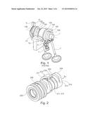
[0016] FIG. 1 a known variable stroke gas exchange valve train,
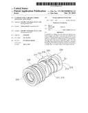
[0017] FIG. 2 a first embodiment of a cam part according to the invention in perspective view,
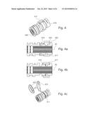
[0018] FIGS. 2a-e the first cam part in different mounting positions of the bearing ring,
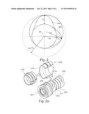
[0019] FIG. 3 the geometry of a cam part according to the invention in schematic view A according to FIG. 2,
[0020] FIG. 4 a second embodiment of a cam part according to the invention in perspective view,
[0021] FIGS. 4a-f the second cam part from FIG. 4 in different mounting positions of the bearing ring,
[0022] FIG. 5 a third embodiment of a cam part according to the invention in longitudinal section,
[0023] FIG. 6 a fourth embodiment of a cam part according to the invention in longitudinal section,
[0024] FIG. 7 a fifth embodiment of a cam part according to the invention in longitudinal section.
DETAILED DESCRIPTION OF THE PREFERRED EMBODIMENTS
[0025] The invention will be explained starting from FIG. 1, which shows a three-stage variable stroke gas exchange valve train of an internal combustion engine. The basic functional principle of this known valve train can be summarized in that a conventionally rigid camshaft is replaced by a camshaft with a carrier shaft 1 with external teeth and--cam parts 102 arranged locked in rotation on this carrier shaft--corresponding to the number of cylinders of the internal combustion engine--and displaceable between three axial positions. Each cam part has two identical groups of directly adjacent cams 103 to 105 that have different strokes with identical reference circle radii. The cam lift is performed by roller cam followers 6 that transfer the cam travels selectively to gas exchange valves 7.
[0026] The displacement of the cam part 102 required for operating point-dependent activation of each cam 103, 104, or 105 on the carrier shaft 1 is realized by a groove-shaped axial connecting link 108 in which, depending on the instantaneous axial position of the cam part, one of two pin-shaped actuation elements 9, 10 of an electromagnetic actuator (not shown) is coupled, in order to displace the cam part within the common reference circle phase of the cam. To stabilize the cam part in the axial positions, a locking device is used that runs (not visible here) in the interior of the carrier shaft 1 and locks in the interior of the cam part.
[0027] For the radial support of the camshaft in the internal combustion engine, the cam part 102 is provided between the two cam groups with a bearing journal 111 that is supported so that it can rotate in a camshaft bearing point 12 arranged locked in position and cylindrically centered in the internal combustion engine. This is a split camshaft bearing point with a screwed-on bearing cover not shown here. Shown is a hydrodynamic sliding bearing of the bearing journal in the camshaft bearing point, wherein the bearing could also be formed in a known way as a roller bearing.
[0028] FIG. 2 shows a first embodiment of a cam part 202 for a two-stage variable stroke gas exchange valve, wherein the bearing journal 211 of the cam part is enclosed by a roller bearing 213 in a way according to the invention. Differently than in the known cam part 102 in FIG. 1, the cam strokes of the first cam group arranged at a distance to the axial connecting link 208 are oriented so that the stroke h1 of the one cam 203 adjacent to the bearing journal is smaller than the stroke h2 of the other cam 204. For this first cam group, the following relationship is then applicable:
a) h1<h2 (see also FIG. 3)
[0029] The cutaway and greatly simplified roller bearing 213 is a needle bearing with cage-supported needles 214, whose inner raceway 215 is formed by the bearing journal 211 and whose outer raceway 216 is formed by a one-part bearing ring 217 drawn onto the cam part 202. The plastic needle cage 218 is shown as needle ring 19 below in connection with the needles held therein, i.e., as 219 in FIG. 2. The width of the bearing ring 217 is approximately twice as large as the length of the needles 214 that roll, depending on the axial position of the cam part, either in one axial raceway half or in the other axial raceway half of the bearing ring mounted in the internal combustion engine.
[0030] FIG. 3 illustrates the geometric radii or diameter relationships on the cam part 202 (cam parts 402 to 702 accordingly) that are projected according to view A in FIG. 2 in the plane of the sheet. The two cams 203 and 204 have a common enveloping circle with radius rHK that encloses the same reference circle radius rGK and the two different strokes h1 and h2 of this cam. In the shown case, however, the smaller stroke h1 runs, with respect to its angular position, not completely within the larger stroke h2, and the circumferential radius rGK+h1 of the cam 203 rotating about the camshaft axis 20 is greater than the common enveloping circle radius rHK. The smallest possible radius rL of the outer raceway 216 for the installation of the bearing ring 217 is now generally the larger value of these two radii rGK+h1 and rHK, so that the following relationship is also applicable:
b1) max {rHK; rGK+h1}<rL
[0031] On the other hand, in order to keep the radial installation space of the cam part 202 with the needle bearing 213 as small as possible, the relationship, according to which the outer raceway radius rL is smaller than the revolution radius of the greater cam 204 about the camshaft axis 20, is also applicable:
b2) rL<rGK+h2
[0032] Example calculation for the outer raceway radius rL for the cam geometry according to FIG. 3:
[0033] From
[0034] rGK: 15.0 mm
[0035] h1: 6.4 mm
[0036] h2: 11.3 mm
[0037] gives
[0038] rHK: 20.6 mm
[0039] rGK+h1: 21.4 mm
[0040] max {rHK; rGK+h1}=21.4 mm
[0041] rGK+h2: 26.3 mm
[0042] and the following size relationship is applicable for the outer raceway radius:
[0043] 21.4 mm<rL<26.3 mm
[0044] The drawing of the bearing ring 217 on the cam part 202 will be explained with reference to FIGS. 2a to 2e.
[0045] FIG. 2a: The needle ring 219 open on the periphery is expanded elastically in the radial direction and is snapped onto the bearing journal 211 from the lateral direction. The width of the needle cage 218 and the width of the bearing journal are essentially the same size, so that the needle cage is supported directly in the axial direction from the facing end sides 221 and 222 of the inner cam 204 of the second cam group and cam 203, respectively, adjacent to the bearing journal.
[0046] FIG. 2b: The bearing ring 217 is threaded eccentric to the camshaft axis 20 onto the outer cam 204. In this case, the smaller stroke h1 extends with respect to its angular position completely within the larger stroke h2, and the radius rL of the outer raceway 216 is slightly greater than the common enveloping circle radius rHK of the cam 203, 204 with rHK=1/2 (2 rGK+h2). The drawn radius rAK designates the outer circumferential radius of the axial connecting link 208 and is also greater than the outer raceway radius rL:
c) rL<rAK
[0047] FIG. 2c: The bearing ring 217 is pushed into the eccentric position over the outer cams 203, 204 until the outer cam 204 is free.
[0048] FIG. 2d: The bearing ring 217 is centered on the camshaft axis 20.
[0049] FIG. 2e: The bearing ring 217 is pushed over the needles 214.
[0050] FIG. 4 shows a second embodiment of a cam part 402 according to the invention. This differs from the previously explained cam part 202 essentially by the axial support of the needle cage 418. Pulling the bearing ring 417 onto the cam part will be explained with reference to FIGS. 4a to 4f.
[0051] FIG. 4a: The bearing ring 417 is threaded eccentric to the camshaft axis 20 onto the outer cam 404 and pushed over the outer cams 403 and 404 until the outer cam 404 is free. The needle ring 419 is pushed toward the inner cam group to create an axial opening for the bearing ring 417.
[0052] FIG. 4b: The needle ring 419 and the bearing ring 417 centered relative to the camshaft axis 20 are pushed one onto the other.
[0053] FIG. 4c: A plastic spacer ring 423 that is open on the periphery is expanded elastically in the radial direction and snapped onto the bearing journal 411 from the lateral direction.
[0054] FIG. 4d: The spacer ring 423 is inserted into a ring groove 424 between the inner raceway 415 and the inner cam 404 of the second cam group.
[0055] FIG. 4e: The bearing ring 417 is displaced toward the inner cam 404 until another ring groove 425 is freely accessible between the inner raceway 415 and the outer cam 403.
[0056] FIG. 4f: As in FIG. 4c, another spacer ring 423 is inserted into the other ring groove 425 so that the facing cam end sides 421 and 422 support the needle cage 418 in the axial direction by means of the spacer rings 423.
[0057] FIG. 5 shows a third embodiment of a cam part 502 according to the invention. In this case, the bearing journal 511 is formed with large steps in the radial direction with a raised inner raceway 515, wherein both end sides 526 and 527 of the radial step support the needle cage 518 surrounding these sides in the axial direction.
[0058] FIG. 6 shows a fourth embodiment of a cam part 602 according to the invention. In this fourth embodiment, the axial support of the needle cage 618 is formed from a combination of the support in the second embodiment and the third embodiment: The axial support is realized on one side on the cam end side 621 by means of the spacer ring 623 and on the other side directly on the end side 626 of the radial step.
[0059] FIG. 7 shows a fifth embodiment of a cam part 702 according to the invention. This fifth embodiment is a variant of the fourth embodiment in the way that the spacer ring 723 is formed in one piece on the needle cage 718.
LIST OF REFERENCE NUMBERS
[0060] (without the hundreds place, which refers to the figure number)
[0061] 1 Carrier shaft
[0062] 2 Cam part
[0063] 3 Cam
[0064] 4 Cam
[0065] 5 Cam
[0066] 6 Roller cam follower
[0067] 7 Gas exchange valve
[0068] 8 Axial connecting link
[0069] 9 Actuation element
[0070] 10 Actuation element
[0071] 11 Bearing journal
[0072] 12 Camshaft bearing point
[0073] 13 Roller bearing/needle bearing
[0074] 14 Roller body/needle
[0075] 15 Inner raceway
[0076] 16 Outer raceway
[0077] 17 Bearing ring
[0078] 18 Roller bearing cage/needle cage
[0079] 19 Needle ring
[0080] 20 Camshaft axis
[0081] 21 Cam end side
[0082] 22 Cam end side
[0083] 23 Spacer ring
[0084] 24 Annular groove
[0085] 25 Additional annular groove
[0086] 26 End side of radial step
[0087] 27 End side of radial step
User Contributions:
Comment about this patent or add new information about this topic:
Images included with this patent application:
 |  |
 |  |
| Similar patent applications: | |
| Date | Title |
|---|---|
| 2016-04-14 | Mechanical lash control for a switchable roller finger follower |
| 2016-03-03 | Controller for variable valve mechanism |
| 2016-05-26 | Controller for variable valve mechanism |
| 2016-03-17 | Variable lost motion valve actuator and method |
| 2016-03-17 | Variable lost motion valve actuator and method |
| New patent applications in this class: | |
| Date | Title |
|---|---|
| 2016-05-12 | Camshaft for an internal combustion engine and use therefore |
| 2016-04-14 | Cylinder head of an internal combustion engine with at least one camshaft |
| 2016-03-31 | Engine for performing cda |
| 2016-03-31 | Continuous variable valve duration apparatus and engine provided with the same |
| 2016-03-17 | Multi-positional camshaft phaser with switchable one-way wedge clutches |
| New patent applications from these inventors: | |
| Date | Title |
|---|---|
| 2016-02-25 | Arrangement of a volume accumulator in a camshaft adjuster |
| 2013-08-08 | Camshaft adjuster having a non-return valve |
| 2013-08-08 | Non-return valve of a camshaft adjuster |
| 2013-08-08 | Filling of a volume accumulator in a camshaft adjuster |
| 2013-08-08 | Non-return valve of a camshaft adjuster |
| Top Inventors for class "Internal-combustion engines" | |
| Rank | Inventor's name |
|---|---|
| 1 | Ross Dykstra Pursifull |
| 2 | Gopichandra Surnilla |
| 3 | Joseph Norman Ulrey |
| 4 | Thomas G. Leone |
| 5 | Chris Paul Glugla |