Patent application title: Slip Release Assembly with Cone Undermining Feature
Inventors:
William C. Lemm (Sugar Land, TX, US)
Assignees:
BAKER HUGHES INCORPORATED
IPC8 Class: AE21B2301FI
USPC Class:
166216
Class name: Wells expansible anchor or casing with wedge or cam and friction drag
Publication date: 2015-10-15
Patent application number: 20150292284
Abstract:
A slip release mechanism provides for undermining the slip cone in the
set position of the slips so that the grip of the slips can be released
subsequent to allowing the cone ramp to flex. The slips can be pulled
back down the cone ramp as the completion of the same motion that
undermines the support for the cone.Claims:
1. A fixation assembly for a subterranean tool, comprising: a mandrel; at
least one slip assembly mounted to said mandrel; a cone mounted to said
mandrel for selectively guiding said slip assembly radially away from
said mandrel, said cone selectively collapsible toward said mandrel when
said slip assembly is engaged to a surrounding tubular to facilitate
release of grip by said slip assembly from the surrounding tubular.
2. The assembly of claim 1, wherein: said cone further comprising at least a first and a second radially stacked components.
3. The assembly of claim 2, wherein: said first and said second components are relatively movable.
4. The assembly of claim 3, wherein: said mandrel engaging said second component to translate said second component axially away from said first component that comprises a tapered surface for engaging said slip assembly.
5. The assembly of claim 4, wherein: said mandrel movable axially for a predetermined distance before engaging said second component for tandem movement.
6. The assembly of claim 2, wherein: said second component initially secured to said slip assembly with a breakable member.
7. The assembly of claim 1, wherein: a broken portion of said breakable member enters a recess on said mandrel to facilitate tandem axial movement of said mandrel and said second component.
8. The assembly of claim 1, wherein: said cone comprising an undercut facing said mandrel that is selectively occupied by a support sleeve.
9. The assembly of claim 8, wherein: said support sleeve disposed in said undercut as said slip assembly moves away from said mandrel on a tapered surface of said cone.
10. The assembly of claim 9, wherein: said mandrel selectively removing said support sleeve from said undercut for grip release by said slip assembly in response to flexing of said cone, enabled by movement of said sleeve.
11. The assembly of claim 10, wherein: said support sleeve initially secured to said slip assembly with a breakable member.
12. The assembly of claim 11, wherein: said breakable member shears as said slip assembly moves on said tapered surface of said cone away from said mandrel.
13. The assembly of claim 12, wherein: a portion of said sheared breakable member engages a recess in said mandrel.
14. The assembly of claim 13, wherein: tandem movement of said mandrel and support sleeve using said sheared breakable member positioned in said recess removes said support sleeve from said undercut.
Description:
CROSS REFERENCE TO RELATED APPLICATION
[0001] This application is claims priority from U.S. Provisional Patent Application Ser. No. 61/979,751 for "Slip Release Assembly with Cone Undermining Feature", filed on Apr. 15, 2014, the disclosure of which is incorporated herein by reference in its entirety..
FIELD OF THE INVENTION
[0002] The field of the invention is slips for anchoring subterranean tools and more particularly a release device for the slips that features undermining the slip cone.
BACKGROUND OF THE INVENTION
[0003] Slips are typically extended by relative movement with respect to an adjacent cone. As the slip element rides up the cone it is moved radially toward a surrounding tubular. The leading face of each slip has a surface treatment commonly referred to as wickers which can be made of a hard material such as tungsten carbide or polycrystalline diamonds to enhance the bite of the slips into the surrounding tubular. Typically the wickers penetrate the inner wall of the pipe to facilitate the grip. Slips commonly anchor isolation devices such as packers and bridge plugs.
[0004] The common issue with slips is to get them to release especially after being set a very long time or after being exposed to extreme loading or operating conditions. Typically, force is applied to the slip element to try to pull the cone out from under the slip. Other designs apply a force to the slip to try to force the slip to ride down on the cone for a release of the wickers. Sometimes, especially after a long period of being in a set position and in a debris laden environment it becomes difficult to get the slips to release. Sometimes the slips refuse to fully release and a milling operation that is very expensive is needed to enable removal of the associated device.
[0005] Prior designs guide the slips at their edges to make sure they don't cock when being extended and to allow them to tangentially transfer radial loading when part of a continuous slip ring. Typical of some of the one piece slip arrangements are: U.S. Pat. No. 4,311,196; GB 2323869; U.S. Pat. No. 6,213,204; U.S. Pat. No. 5,487,427; U.S. Pat. No. 5,174,397; U.S. Pat. No. 3,279,544; and U.S. Pat. No. 6,241,017.
[0006] Still other designs focus on slip guidance and extension while using the traditional techniques for slip release. Such designs are: U.S. Pat. Nos. 7,416,027; 8,291,989; 4,359,090; 6,213,204; 6,131,663; 6,629,563; 5,701,954; 4,573,537; 8,459,347; 2011/0088891; 3,352,362; 5,273,109; 5,487,427; 5,727,632; 6,220,348; 6,827,150; 7,051,805; 8,186,446; 8,205,671 and 8,534,368.
[0007] These designs still present an issue of difficult release and the present invention presents a design to deal with this issue. The design features a two piece construction for the slip cone that lends support to the slip cone when the slips move out along the cone. For release, a piece is pulled out from under the cone to release the slip above the cone so that the slip can be easily retracted. These and other features of the present invention will be more readily apparent to those skilled in the art from a review of the description of the preferred embodiment and the associated drawings while recognizing that the full scope of the invention is to be determined from the appended claims.
[0008] SUMMARY OF THE INVENTION A slip release mechanism provides for undermining the slip cone in the set position of the slips so that the grip of the slips can be released subsequent to allowing the cone ramp to flex. The slips can be pulled back down the cone ramp as the completion of the same motion that undermines the support for the cone.
BRIEF DESCRIPTION OF THE DRAWINGS
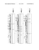
[0009] FIG. 1 is a section view in the run in position;
[0010] FIG. 2 is the view of FIG. 1 in the set position; and
[0011] FIG. 3 is the view of FIG. 2 in the released position.
DETAILED DESCRIPTION OF THE PREFERRED EMBODIMENT
[0012] Referring to FIG. 1 the slip assembly 10 is shown in the run in position. Cone 12 is supported from mandrel 14 by sleeve 16. Sleeve 16 is initially held to the outer assembly 19. Outer assembly 19 holds the slips 20 against axial movement when the cone 12, sleeve 16 and retainer 26 move up axially with respect to the mandrel 14 for the set position shown in FIG. 2. Ramp 22 on the cone 12 engages ramp 24 on the slips 20 as the slips 20 move out radially to engage the surrounding tubular for the set position.
[0013] As seen in FIG. 2 the upward movement of the cone 12 takes with it sleeve 16 as the shear device 18 breaks. A retainer 26 sits in an opening 28 of the sleeve 16. When the shear device 18 breaks and the set position of FIG. 2 is reached, the retainer 26 is no longer retained by the now broken shear device 18. Retainer 26 is now able to fall radially inwardly into groove 30. Groove 30 has a retrieval surface 32 at its lower end designed to engage retainer 26 for undermining the cone 12 by pulling out the sleeve 16 out from under it as shown in FIG. 3. The parts are proportioned so that the sleeve 16 is first removed from under cone 12 before further picking up of mandrel 14 engages outer assembly 19 to pull the slips 12 down ramp 22 of the cone 12 for the fully released position.
[0014] Those skilled in the art will appreciate that by initially undermining the cone with the slips extended, the slips are no longer wedged against the surrounding tubular and as a follow on movement can be retracted down the ramp that defines the cone. The sleeve 16 may engage the cone on a single or multiple surfaces 38, 40 and 42 with substantially parallel surfaces 44, 46 and 48 respectively. These surfaces can be parallel to the axis of the mandrel as illustrated in the drawing or at a skew to the mandrel 14 axis. The end of sleeve 16 can be a complete cylindrical shape or can have cutouts or slots to make retraction shown in FIG. 3 simpler. The cone 12 can also be a 360 degree ramp or can have cutouts or slots to the end or on the ramp for the same reason. The sleeve and associated cone can have similar or dissimilar features designed to facilitate release of sleeve 16 from under the cone 12. Other alternatives are contemplated such as a change in shape for the sleeve 16 in response to well conditions. One example is to use a shape memory alloy for the sleeve 16 that responds to added heat to reduce in thickness to facilitate removal.
[0015] The above description is illustrative of the preferred embodiment and many modifications may be made by those skilled in the art without departing from the invention whose scope is to be determined from the literal and equivalent scope of the claims below:
User Contributions:
Comment about this patent or add new information about this topic:
Images included with this patent application:
 |  |
| Similar patent applications: | |
| Date | Title |
|---|---|
| 2016-03-17 | Seal with soft material inlay |
| 2016-05-19 | Metal bellows with guide rings |
| 2015-11-05 | Self-assembling packer |
| 2016-01-28 | Multi-purpose through tubing tool |
| 2016-02-04 | Drilling riser assemblies |
| New patent applications in this class: | |
| Date | Title |
|---|---|
| 2015-04-02 | Anchor mechanism for use in a well |
| 2014-11-20 | Slip with altering load distribution feature |
| 2014-09-18 | Bonded segmented slips |
| 2012-07-26 | Tapered dog configuration to share stress in a housing of a subterranean tool |
| 2012-06-21 | System and method for anchoring an expandable tubular to a borehole wall |
| New patent applications from these inventors: | |
| Date | Title |
|---|---|
| 2015-10-15 | Relatively movable slip body and wicker for enhanced release capability |
| Top Inventors for class "Wells" | |
| Rank | Inventor's name |
|---|---|
| 1 | Michael L. Fripp |
| 2 | Jean Marc Lopez |
| 3 | Michael H. Johnson |
| 4 | Jørgen Hallundbaek |
| 5 | Dennis P. Nguyen |