Patent application title: Portable Table Number Device and Table Number System
Inventors:
Steve Rakoczy (Perth, AU)
Steve Rakoczy (Perth, Western Australia, AU)
Steven Thomas Mcguinness (Perth, AU)
Assignees:
Almnos Technologies Pty. Ltd.
IPC8 Class: AG06K1907FI
USPC Class:
Class name:
Publication date: 2015-10-08
Patent application number: 20150286917
Abstract:
A portable table number device, comprising a housing having a bottom side
with an outer edge arranged to rest on a table surface, said housing
comprising a power source, an RFID reader arranged to detect an RFID
table ID tag on or under said table surface, computer memory means
comprising a table number device ID, wireless communication means
arranged to wirelessly communicate a detected RFID tag table ID by said
RFID reader together with said table number device to an external table
number ID receiving device, a surface proximity sensor, such as a light
sensor or micro-switch arranged in a recessed portion of said housing
within said outer edge, said surface proximity sensor having a first
state wherein no proximate surface is detected and a second state wherein
a proximate surface is detected, said second state occurring if said
bottom side of said housing is placed on said table surface, and power
management means arranged to keep said RFID reading device in a sleep
mode wherein no or relatively little power is used until the state of
said surface proximity sensor changes from said first state to said
second state, to power up said RFID reader temporarily for a period of
time if the state of said proximity sensor changes from said first state
to said second state, said period of time being long enough to enable
said RFID reader to identify an RFID tag and transmit it to said external
table number receiving device, and to put said RFID reader in said sleep
mode after said period of time lapses.Claims:
1. A portable table number device, comprising: a housing having a bottom
side with an outer edge arranged to rest on a table surface, said housing
comprising a power source; an RFID reader arranged to detect an RFID
table ID tag on or under said table surface; computer memory means
comprising a table number device ID; wireless communication means
arranged to wirelessly communicate a detected RFID tag table ID by said
RFID reader together with said table number device ID to an external
table number receiving device; a surface proximity sensor arranged in a
recessed portion of said housing within said outer edge, said surface
proximity sensor having a first state wherein no proximate surface is
detected and a second state wherein a proximate surface is detected, said
second state occurring if said bottom side of said housing is placed on
said table surface; and power management means arranged to keep said RFID
reading device in a sleep mode wherein no or relatively little power is
used until the state of said surface proximity sensor changes from said
first state to said second state, to power up said RFID reader
temporarily for a period of time if the state of said proximity sensor
changes from said first state to said second state, said period of time
being long enough to enable said RFID reader to identify an RFID tag and
transmit it to said external table number receiving device, and to put
said RFID reader in said sleep mode after said period of time lapses.
2. The device in accordance with claim 1, wherein said power management means is arranged to put said RFID reader in said sleep mode once said RFID tag identification has been completed even if said period of time has not yet lapsed.
3. The device in accordance with claim 1, wherein said power management means is arranged to keep the communication means in a sleep mode in sync with the RFID reader.
4. The device in accordance with claim 1, wherein said housing is provided with a visible identifier representing said unique device ID, such as a number, which is readable for an average person at a distance of at least several meters.
5. The device in accordance with claim 4, wherein said visible identifier is attached to said housing by means of an upright post.
6. The device in accordance with claim 1, wherein said power source is a battery, a capacitor and/or a solar panel.
7. The device in accordance with claim 1, wherein said wireless communication means are WiFi communication means.
8. The device in accordance with claim 1, wherein each table number device comprises at least two of said surface proximity sensors a distance apart, and the power management means is arranged to power up the RFID reader for said period of time if the state of both of said surface proximity sensors changes from said first state to said second state.
9. The device in accordance with claim 1, wherein said surface proximity sensor is a light sensor, wherein said first state is a state wherein relatively much light is detected, and said second state is a state wherein relatively little or no light is detected.
10. The device in accordance with claim 1, wherein said surface proximity sensor is a micro-switch.
11. Table number system comprising a multitude of table number devices in accordance with claim 1, each table number device having a unique table number device ID, a multitude of RFID table number tags, and a table number receiving device arranged to wirelessly receiving said pairs of RFID tag table numbers and device IDs and to communicate said pairs of device IDs and RFID tag table numbers, or the location thereof, to users of said table number system.
12. The system in accordance with claim 11, wherein said table number receiving device is a computer comprising software for managing client orders, such as restaurant or cafe orders.
Description:
[0001] The invention relates to a portable table number device.
[0002] In restaurants or cafes having a central counter where clients order and/or pay for meals or drinks, the clients are given a pod or the like displaying a number and choose a table to wait for their order to be served to them. Such a pod or the like is commonly called a "table number". The pod is placed on the chosen table, visible for the waiters. When the order is ready to be served, the waiter reads the order number on the printed slip and searches the restaurant or cafe for the table with the corresponding pod on it, and serves the order to the client. A more appropriate name for the "table number" would be "order number", but in this document we will follow the usual terminology of the industry.
[0003] In large restaurants or cafes this raises the problem that it takes waiters a relatively long period of time to find the right table number. Therefor it would be advantageous to use electronic tracking of the table numbers. Such a solution, based on RFID (Radio Frequency Identification) technique is described in US 2008/0288357 A1, whereby each table has an RFID tag and the table number device incorporates an RFID reader. However, for such a system to be commercially viable, the RFID readers have to operate for extended periods of time, while the operation of an RFID reader requires substantial amount of power. The invention aims at an efficient, reliable solution of this problem.
[0004] According to the invention the table number device comprises a housing having a bottom side with an outer edge arranged to rest on a table surface, said housing comprising a power source, an RFID reader arranged to detect an RFID table ID tag on or under said table surface, computer memory means comprising a table number device ID, wireless communication means arranged to wirelessly communicate a detected RFID tag table ID by said RFID reader together with said table number device ID to an external table number receiving device, a surface proximity sensor, such as a light sensor or a micro-switch, arranged in a recessed portion of said housing within said outer edge, said surface proximity sensor having a first state wherein no proximate surface is detected and a second state wherein a proximate surface is detected, said second state occurring if said bottom side of said housing is placed on said table surface, and power management means arranged to keep said RFID reading device in a sleep mode wherein no or relatively little power is used until the state of said surface proximity sensor changes from said first state to said second state, to power up said RFID reader temporarily for a period of time if the state of said light sensor changes from said first state to said second state, said period of time being long enough to enable said RFID reader to identify an RFID tag and transmit it to said external table number receiving device, and to put said RFID reader in said sleep mode after said period of time lapses. The invention in particular relates to a table number system comprising a multitude of said table number devices, each table number device having a unique device ID, a multitude of RFID table number tags, and a table number receiving device arranged to wirelessly receiving said pairs of RFID tag table numbers and device IDs and to communicate said pairs of device IDs and RFID tag table numbers, or the location thereof, to users of said table number system. Said table number receiving device is for instance a computer comprising software for managing client orders, such as restaurant or cafe orders.
[0005] Preferably said surface proximity sensor is a light sensor, wherein said first state is a state wherein relatively much light is detected, and said second state is a state wherein relatively little or no light is detected.
[0006] Said wireless communication means may for instance be WiFi communication means. Said power source may for instance be a battery or a solar panel. The RFID tag reader uses a relatively large amount of power, but by using a power management means in accordance with the invention the table number devices can be used with small, compact batteries or even "supercap" type capacitors in a reliable manner for long periods of time. The RFID reader is only powered for a short period of time after the device touches the table surface. Using a customer operated device, such as a power switch, would not be practical as it would require cooperation by the customers. When the devices are not used, they may be placed on any surface where they sit idle or they may be put on a wireless charging surface.
[0007] Said power management means is preferably arranged to put said RFID reader in said sleep mode once said RFID tag identification has been completed even if said period of time has not yet lapsed. Said power management means is further preferably arranged to keep the communication means in a sleep mode in sync with the RFID reader.
[0008] Said housing is preferably provided with a visible identifier representing said unique device ID, such as a number, which is readable for an average person at a distance of at least several meters. In a preferred embodiment said visible identifier is attached to said housing by means of an upright post.
[0009] Each table number device preferably comprises at least two of said surface proximity sensors a distance apart, and the power management means is arranged to power up the RFID reader for said period of time if the state of both of said surface proximity sensors changes from said first state to said second state. By using at least two sensors accidental powering of the RFID reader if for instance a user covers the sensor with a hand, is prevented.
[0010] The invention will now be exemplified by means of a preferred embodiment, with reference to the figures, wherein:
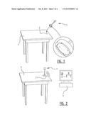
[0011] FIG. 1 is a perspective view of a table number system in accordance with the invention with a table number device in a first state;
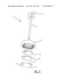
[0012] FIG. 2 is a perspective view of the table number system of FIG. 1 with the table number device in a second state;
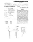
[0013] FIG. 3 is a perspective exploded view of the table number device of FIGS. 1 and 2.
[0014] According to the figures, a table number system comprises a multitude of table number devices 1, a multitude of table identifier tags 2 and a computer 3 loaded with restaurant or cafe order management software.
[0015] Tables 4 in a restaurant provided with a unique RFID table identifier tag 2, for instance in the form of a sticker on the table surface. The sticker may be provided with user instructions like "PLACE THE TABLE NUMBER HERE". The table number device 1 comprises a disc shaped pod 5, and a plate 6 on a pole 7. A visible table number is printed on the plate 6, and user instructions may also be printed on the device.
[0016] The pod 5 forms a housing for the electronic components and comprises a controller board 9 with a battery, power management means and wireless communication means which can communicate data received from the RFID reader to wireless communication means of the computer 3, an interface board 10 with the RFID reader and (preferably two) light sensors 8, and a transparent bottom cover 11.
[0017] Normally the RFID reader and the wireless communication means are off or in a sleep mode. When a client places an order at a central counter, he or she will receive a table number device 1 and be requested to find a table 4 in the restaurant or cafe and put the device 1 on the sticker with RFID tag 2.
[0018] When the pod 5 is moved from the position as shown in FIG. 1, wherein the bottom side of the pod 5 is uncovered, to the position as shown in FIG. 2, wherein the bottom side of the pod 5 is placed on the RFID tag 2 on the top surface of the table 4, the state of the light sensors 8 changes from "sensing light" to "not sensing light". The power management means, which are connected to the light sensors 8, is arranged to react to this event and power the RFID reader and the wireless communication means for a predetermined period of time, such that the RFID reader can detect any RFID table identifier tag 2 present, and the wireless communication means can communicate the detected table identifier ("5") together with the table number ("2") to the computer 3. Once this is completed, or if no RFID tag is detected in the predetermined period of time, the power management means put the RFID reader and the wireless communication means to sleep. The computer 3 is arranged to show the table number (actually order number) and the table identifier on the monitor or to print this on the order slip, such that the personnel know where to find the table number device 1 in order to deliver the order to the client. Alternatively, the location of the table number can be shown on a map of the layout of the restaurant or cafe by superimposing the active--not yet serviced--table numbers (order numbers) on top of the table symbols.
[0019] The invention has thus been described by means of a preferred embodiment. It is to be understood, however, that this disclosure is merely illustrative. Various details of the structure and function were presented, but changes made therein, to the full extent extended by the general meaning of the terms in which the appended claims are expressed, are understood to be within the principle of the present invention. The description and drawings shall be used to interpret the claims. The claims should not be interpreted as meaning that the extent of the protection sought is to be understood as that defined by the strict, literal meaning of the wording used in the claims, the description and drawings being employed only for the purpose of resolving an ambiguity found in the claims. For the purpose of determining the extent of protection sought by the claims, due account shall be taken of any element which is equivalent to an element specified therein.
User Contributions:
Comment about this patent or add new information about this topic:
Images included with this patent application:
 |  |
 |
| New patent applications in this class: | |
| Date | Title |
|---|---|
| 2022-09-08 | Shrub rose plant named 'vlr003' |
| 2022-08-25 | Cherry tree named 'v84031' |
| 2022-08-25 | Miniature rose plant named 'poulty026' |
| 2022-08-25 | Information processing system and information processing method |
| 2022-08-25 | Data reassembly method and apparatus |
| New patent applications from these inventors: | |
| Date | Title |
|---|---|
| 2015-11-05 | Wireless charging system |
| 2013-08-15 | Pump assembly for a marine toilet and toilet pump connection system |
| 2013-02-14 | System for detection of turbulent air flow across a sail of a sailboat |