Patent application title: PORTABLE SUPPORT DEVICE FOR PORTABLE ELECTRONIC DEVICE
Inventors:
Gang Feng (Shenzhen, CN)
IPC8 Class: AA45C1100FI
USPC Class:
224191
Class name: Package and article carriers carried by animate bearer article held by receiver
Publication date: 2015-05-07
Patent application number: 20150122852
Abstract:
A portable support device for a portable electronic device is provided.
The portable support device includes an attachment member selectively
attachable to the portable device and a support member coupled to the
attachment member. The support member is configured to be supported by at
least one finger of a user.Claims:
1. A portable support device for a portable electronic device,
comprising: an attachment member selectively attachable to the portable
device; and a support member coupled to the attachment member, the
support member being configured to be supported by at least one finger of
a user.
2. The portable support device as claimed in claim 1, wherein the support member comprises a ring element configured to encompass at least one finger of the user.
3. The portable support device as claimed in claim 2, wherein the attachment member comprises an attachment portion and a protruding portion extending from the attachment portion, the attachment portion is configured to attach to the portable electronic device, the protruding portion is configured to couple to the support member.
4. The portable support device as claimed in claim 3, wherein the attachment portion is a suction cup suctionably attachable to the portable electronic device.
5. The portable support device as claimed in claim 3, wherein the attachment portion is a magnet magnetically attachable to the portable electronic device.
6. The portable support device as claimed in claim 3, wherein the protruding portion is columnar, the distal end of the protruding portion opposite to the attachment portion defines a clamping flange.
7. The portable support device as claimed in claim 6, wherein the support member further comprises a connecting portion extending from the ring element, the connecting portion is mounted to the protruding portion.
8. The portable support device as claimed in claim 7, wherein the connecting portion is a hollow column and defines a fixing hole for rotatably engaging the clamping flange.
9. The portable support device as claimed in claim 8, wherein a clamping portion extends from a distal end of the connecting portion toward the fixing hole, the clamping portion resists against the clamping flange.
10. The portable support device as claimed in claim 9, wherein a plurality of slots interconnecting with the fixing hole is defined in the clamping portion.
11. The portable support device as claimed in claim 1, wherein the ring element has an outer surface and an inner surface, and a plurality of holes is defined through the outer surface and the inner surface.
Description:
FIELD
[0001] The present disclosure generally relates to a portable support device for a portable electronic device.
BACKGROUND
[0002] Many people use portable electronic devices such as mobile phones and personal digital assistants (PDAs). In the case of walking, sitting in a bus or subway train, users may need suitable support devices for supporting the electronic devices.
BRIEF DESCRIPTION OF THE DRAWINGS
[0003] Implementations of the present technology will now be described, by way of example only, with reference to the attached figures, wherein:
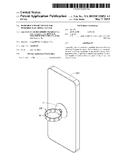
[0004] FIG. 1 is an isometric view of an exemplary portable support device having an attachment member and a support member being used.
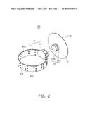
[0005] FIG. 2 is an exploded view of the portable support device of FIG. 1.
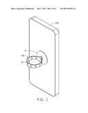
[0006] FIG. 3 is a partial enlarged isometric view of the attachment member of FIG. 1, but viewed from another angle.
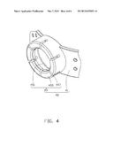
[0007] FIG. 4 is a partial enlarged view of the support member of the portable support device of FIG. 1.
DETAILED DESCRIPTION
[0008] It will be appreciated that for simplicity and clarity of illustration, where appropriate, reference numerals have been repeated among the different figures to indicate corresponding or analogous elements. In addition, numerous specific details are set forth in order to provide a thorough understanding of the embodiments described herein. However, it will be understood by those of ordinary skill in the art that the embodiments described herein can be practiced without these specific details. In other instances, methods, procedures and components have not been described in detail so as not to obscure the related relevant feature being described. Also, the description is not to be considered as limiting the scope of the embodiments described herein. The drawings are not necessarily to scale and the proportions of certain parts have been exaggerated to better illustrate details and features of the present disclosure.
[0009] Several definitions that apply throughout this disclosure will now be presented.
[0010] The term "coupled" is defined as connected, whether directly or indirectly through intervening components, and is not necessarily limited to physical connections. The connection can be such that the objects are permanently connected or releasably connected. The term "comprising," when utilized, means "including, but not necessarily limited to"; it specifically indicates open-ended inclusion or membership in the so-described combination, group, series and the like.
[0011] FIG. 1 illustrates a portable support device 100 according to an exemplary embodiment. The portable support device 100 can be used for supporting a portable electronic device 200. In this embodiment, the portable electronic device 200 is a mobile phone. The portable support device 100 includes an attachment member 10 and a support member 40 coupled to the attachment member 10. The attachment member 10 can attach to the portable electronic device 200.
[0012] FIGS. 2 and 3 illustrate that the attachment member 10 includes an attachment portion 11 and a protruding portion 15 extending from one side of the attachment portion 11. In this embodiment, the attachment portion 11 is a suction cup suctionably attachable to the portable electronic device. The attachment portion 11 can be made of elastic material, and can define a recess 113 on the side opposite to the protruding portion 15 as shown in FIG. 3. The attachment portion 11 can be suctioned to the surface of the portable electronic device 200 by positioning the attachment portion 11 on the portable electronic device 200, and squeezing the attachment portion 11 to exhaust air from the recess 113.
[0013] In other embodiments, the attachment member 10 can be replaced with a magnet magnetically attachable to the portable electronic device, in this case, the portable electronic device 200 is required to have a housing made of ferromagnetic materials.
[0014] The protruding portion 15 is configured to couple to the support member 40. The protruding portion 15 is shaped like a column. An annular groove 155 is defined on the circumference of the protruding portion 15. The distal end of the protruding portion 15 opposite to the attachment portion 11 defines a clamping flange 158.
[0015] The support member 40 includes a ring element 41 and a connecting portion 45 extending from the ring element 41 as shown in FIG. 2. The ring element 41 is configured to encompass at least one finger of a user. In this embodiment, the ring element 41 encompasses one finger. The ring element 41 has an outer surface 413 and an inner surface 415. The ring element 41 defines a plurality of holes 417 through the outer surface 413 and the inner surface 415. The holes 417 can increase the friction between the finger and the ring element 41, and can also improve ventilation.
[0016] The connecting portion 45 extends from the outer surface 413 of the ring element 41. In this embodiment, the connecting portion 45 is rotatably mounted to the protruding portion 15. As shown in FIG. 4, the connecting portion 45 is hollow columnar. A fixing hole 451 is defined in the connecting portion 45 for engaging the clamping flange 158. A clamping portion 455 extends from a free distal end of the connecting portion 45 toward the fixing hole 451. The clamping portion 455 resists against the clamping flange 158 and is received in the annular groove 155. A plurality of slots 457 interconnecting with the fixing hole 451 is defined in the clamping portion 455. The clamping portion 455 can expand due to the forming of the slots 457 when the protruding portion 15 is engaged in the connecting portion 45. The support member 40 can be made of elastic plastic, or metal.
[0017] In use, the portable electronic device 200 can be suctioned to the attachment member 10. The finger can fit in the ring element 41. The attachment member 10 can rotate about the connecting portion 45, enabling the portable electronic device 200 to be moved to an appropriate viewing position.
[0018] In other embodiments, the connecting portion 45 can also be unable to rotate while coupled to the protruding portion 15.
[0019] It is believed that the exemplary embodiment and its advantages will be understood from the foregoing description, and it will be apparent that various changes may be made thereto without departing from the spirit and scope of the disclosure or sacrificing all of its advantages, the examples hereinbefore described merely being preferred or exemplary embodiment of the disclosure.
User Contributions:
Comment about this patent or add new information about this topic:
Images included with this patent application:
 |  |
 |  |
 |
| Similar patent applications: | |
| Date | Title |
|---|---|
| 2014-11-27 | Attachable fix point strip |
| 2015-03-26 | Articulable shoulder strap |
| 2011-01-13 | Support structure |
| 2013-07-04 | Bicycle support bar |
| 2013-11-07 | Wearable supports |
| New patent applications in this class: | |
| Date | Title |
|---|---|
| 2019-05-16 | Backpack ornamental attachment system |
| 2017-08-17 | Multistrand lanyard for handheld devices |
| 2016-12-29 | Wearable self-adhering pill container |
| 2016-09-01 | Protective cover and manufacturing method thereof |
| 2016-09-01 | Protective case for portable electronic device |
| Top Inventors for class "Package and article carriers" | |
| Rank | Inventor's name |
|---|---|
| 1 | Chris Sautter |
| 2 | Zac Elder |
| 3 | Peter Douglas Hubbard |
| 4 | Douglas Harland Murdoch |
| 5 | Jeffrey M. Aftanas |