Patent application title: HIGH-SPEED VTOL AIRCRAFT
Inventors:
Geoffrey Byron Greene (Memphis, TN, US)
IPC8 Class: AB64C2900FI
USPC Class:
244 121
Class name: Aeronautics and astronautics aircraft, heavier-than-air airplane and fluid sustained
Publication date: 2015-02-19
Patent application number: 20150048200
Abstract:
This invention can take-off like a helicopter and then roll forward as a
single unit to fly faster and further than any conventional helicopter.
Just like the seats in a Ferris wheel, the payload of passengers or
freight can remain upright and comfortable as this aircraft rotates from
take-off to fast forward and back to landing mode. Prior inventions
claiming similar performance generate lift for take-off and landing by
relative rotation of major aircraft components or by vectoring a thrust
through large angles of deflection which produces inherently unstable
flight characteristics. This invention requires neither rotation of major
assemblies nor highly vectorable thrust, making it simpler and more
reliable than the aircraft with major rotating assemblies and more stable
and efficient than aircraft relying on vectored thrust for lift.Claims:
1. A VTOL aircraft capable of fixed-wing aircraft speed comprising: a) an
airframe into which a payload such as human beings or freight can be
loaded and to which major components that provide propulsion and/or lift
are attached; b) a system for producing a force used for lift during
take-off, landing, and hover, for lift and propulsion in a relatively
slow primarily horizontal flight mode, and for propulsion in fast forward
flight mode, that does not change the general orientation of the force
with respect to the airframe in any of these flight modes; c) at least
one surface providing lift due to flow past it during fast-forward flight
that does not change general orientation with respect to the airframe in
any flight modes.Description:
BACKGROUND--CROSS-REFERENCE TO RELATED APPLICATIONS
[0001] Not applicable
BACKGROUND--FIELD OF THE INVENTION
[0002] This invention relates to vertical take-off and landing aircraft, specifically one that flies much faster and more efficiently than a helicopter.
SEQUENCE LISTING
[0003] Not applicable.
BACKGROUND--DISCUSSION OF PRIOR ART
[0004] Forward flight speed of a conventional helicopter is limited by the aerodynamics of its rotor blades. To achieve higher-speed forward flight, existing Vertical Take-Off and Landing (VTOL) aircraft typically rotate major components such as engines, rotors, and/or wings with respect to each other. This ability to reconfigure major aircraft components in flight adds weight, increases complexity, increases both cost of production and cost of maintenance, and reduces reliability.
SUMMARY
[0005] This invention is capable of true vertical take-off. Transition to high-speed forward-flight is accomplished without changing the aircraft's basic configuration as defined by its major components, (e.g., fuselage, wing, propeller, engines). Transition is accomplished by rotating the unit as a whole about an axis oriented along the length of the fixed wing. Only minor elements such as sensors, displays, controls, lights, seats, or beds may rotate with respect to the major aircraft components to maintain preferred orientation of that minor element.
OBJECTS AND ADVANTAGES
[0006] Accordingly, several objects and advantages of the present invention are:
[0007] (a) Faster forward flight and more efficient than a conventional helicopter;
[0008] (b) Less expensive to produce and maintain than existing VTOL aircraft;
[0009] (c) More reliable than existing VTOL aircraft;
[0010] (d) More efficient than existing VTOL aircraft.
DESCRIPTION OF DRAWINGS
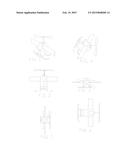
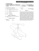
[0011] FIG. 1 is a perspective view of a basic embodiment of my aircraft's unique arrangement of fuselage, propeller and wings in vertical flight mode resembling a helicopter with a fixed wing attached in a fashion similar to attachment of a fin to a rocket.
[0012] FIG. 2 is a top view of the same embodiment in vertical take-off and landing mode.
[0013] FIG. 3 is a top view looking down on the same embodiment sitting on the ground in vertical take-off and landing mode ready to fly up toward the viewer.
[0014] FIG. 4 is a perspective view of the same embodiment rotated to fast-forward flight mode flying toward the right of the viewer.
[0015] FIG. 5 is a front view of the same embodiment in fast-forward flight mode flying toward the viewer.
[0016] FIG. 6 is a top view looking down on the same embodiment in fast-forward flight mode flying toward the right of the viewer.
DESCRIPTION AND OPERATION OF THE INVENTION
[0017] The purpose of this invention is to provide an aircraft with good vertical take-off and landing capabilities, a bonus of slow flight in any direction, and the ability to rotate into an aircraft that flies much faster than a conventional helicopter.
[0018] FIG. 1 depicts a perspective view of an embodiment of the invention sitting on the ground or in low-speed vertical flight mode. During take-off or landing, and during low-speed flight, lift and part of the flight control is provided by a set of rotating blades as in a conventional helicopter, and yaw is induced or limited by control surfaces on the fixed wing. FIG. 2 depicts a side view of the broad side of the fixed wing. In FIG. 3 only the leading edge of the fixed wings can be seen from this top view. The fixed wing works very well during takeoff and landing eliminating the need for a tail rotor. While traveling in low-speed vertical flight mode, a bonus mode of slowly moving in various directions, the fixed wing may produce some undesirable flight characteristics such as unwanted forces due to cross-winds. However, in fast-forward mode the fixed wing more than makes up for any low speed challenges by providing the very important stable lift required for high-speed flight faster than any conventional helicopter.
[0019] On takeoff in vertical flight mode once the aircraft has gained sufficient altitude, the pilot can use a conventional rotor control to roll the craft forward about an axis oriented along the length of the fixed wing. This maneuver accelerates the craft forward, inducing flow over the fixed wing, thereby transferring lift from the rotor to the fixed wing as the rotor's thrust accelerates the craft. Although the angle of attack of this wing initially exceeds the stall angle, the rotor is still providing some lift. As the craft rotates about the axis of the wings and accelerates forward, lift from the fixed wing increases as the lift from the rotor decreases. When the aircraft has completely rotated to fast-forward flight, the rotor supplies thrust as a conventional propeller and maintains control elements as the aircraft's lift is provided by air flowing over the fixed wing as depicted in FIGS. 4, 5, and 6. The entire transition has been accomplished without changing the basic craft's configuration in that no major component has moved with respect to any other major component.
[0020] Transition from fast-forward flight to low-speed flight requires reduction of flight speed. The pilot can use the rotor controls to roll the craft up to a helicopter-like orientation at which point it can be flown to landing as a helicopter.
CONCLUSIONS, RAMIFICATIONS, AND SCOPE OF INVENTION
[0021] While the above description contains many specificities these should not be construed as limitations on the scope of the invention, but rather as exemplifications of one preferred embodiment thereof Many other variations are possible. For example, any mechanism producing appropriate thrust may be used instead of the aforementioned rotor. For example, minor elements such as sensors, displays, controls, lights, seats, or beds may rotate with respect to the major aircraft elements to maintain preferred orientation of that minor element. Accordingly the scope of the invention should be determined not by the embodiments illustrated but by the appended claims and their legal equivalents.
User Contributions:
Comment about this patent or add new information about this topic:
Images included with this patent application:
 |  |
| Similar patent applications: | |
| Date | Title |
|---|---|
| 2015-03-26 | Leading and trailng edge device deflections during descent of an aircraft |
| 2015-03-26 | System and method for optimizing performance of an aircraft |
| 2015-03-05 | High speed composite drive shaft |
| 2015-03-26 | Deicing of a surface of structures in general such as wind turbine blades, aircraft wings using induction or radiation |
| 2015-02-26 | High-lift device of air vehicle |
| New patent applications in this class: | |
| Date | Title |
|---|---|
| 2015-12-24 | Delta m-wing unmanned aerial vehicle |
| 2015-12-17 | Vertical take-off and landing flight vehicle |
| 2014-06-12 | Zero transition vertical take-off and landing aircraft |
| 2013-04-25 | Unmanned aerial vehicle and method of operation |
| 2011-07-14 | Aircraft having a rotating turbine engine |
| New patent applications from these inventors: | |
| Date | Title |
|---|---|
| 2012-02-09 | Large water turbine |
| Top Inventors for class "Aeronautics and astronautics" | |
| Rank | Inventor's name |
|---|---|
| 1 | Bernard Guering |
| 2 | The Boeing Company |
| 3 | Alain Porte |
| 4 | Olivier Cazals |
| 5 | Seiya Sakurai |