Patent application title: VEHICLE-MOUNTED CHARGING DEVICE
Inventors:
Chih-Chen Lai (New Taipei, TW)
Chih-Chen Lai (New Taipei, TW)
IPC8 Class: AH02J700FI
USPC Class:
320107
Class name: Electricity: battery or capacitor charging or discharging cell or battery charger structure
Publication date: 2014-12-11
Patent application number: 20140361731
Abstract:
A vehicle-mounted charging device includes a charging main body, an
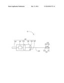
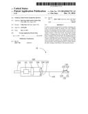
external module, an electric wire, and a lighting module. The charging
main body includes a circuit board in a first shell, a power plug, and a
first shell. A power socket of a vehicle connects to the circuit board.
The external module includes a charging plug and a second shell. The
charging plug is arranged in the second shell. The charging plug connects
to a charging socket of an electronic device to recharge a battery of the
electronic device. The electric wire is configured to electrically
connect to the charging main body, the external module, and the lighting
module to visually indicate the state of charge of the battery of the
electronic device.Claims:
1. A vehicle-mounted charging device (10) comprising: a charging main
body (100) comprising: a circuit board (101); a power plug (102); and a
first shell (106), the circuit board (101) received in the first shell
(106), the power plug (102) configured to connect a power socket of a
vehicle, and the power plug (102) electrically connected to the circuit
board (101); an external module (110) comprising a charging plug (111)
and a second shell (114), the charging plug (111) protruding from the
second shell (114), the charging plug (111) configured for being
electrically connected to a charging socket of an electronic device; an
electric wire(120) having a first end and a second end, the first end
electrically connected to the power plug (102) of the charging main body
(100), and the second end electrically connected to the external module
(110); and a light module (130) comprising a lamp (112) and a switch
(113), wherein the switch (113) and the lamp (112) are arranged on the
second shell (114), the electric wire (120) is electrically connected to
the lamp (112) and switch (113), the switch (113) is electrically
connected to the lamp (112), the lamp (112) is configured for providing
illumination, and the switch (113) is configured to activate and
deactivate the lamp (112).
2. The device of claim 1, wherein the charging main body (110) further comprises a current detecting module (103), a current indicating lamp (104) and an USB interface (105), the current detecting module (103) received in the first shell (106), the current detecting module (103) is electrically connected to the circuit board (101), the current indicating lamp (104) arranged on the surface of first shell (106), the current indicating lamp (104) is electrically connected to the current detecting module (103), access to the USB interface (105) is arranged on the surface of first shell (106), the USB interface (105) is electrically connected to the current detecting module (103).
3. The device of claim 2, wherein the current detecting module (103) is configured for detecting the output current of the USB interface (105) and a output current of the external module (110).
4. The device of claim 2, wherein the current indicating lamp (104) show the state of charge of a battery, with red light or green light.
5. The device of claim 2, wherein the USB interface (105) is configured for connecting the external electronic equipment.
Description:
FIELD
[0001] The present disclosure relates to vehicle-mounted devices.
BACKGROUND
[0002] A charging device is necessary in any field where rechargeable batteries are used.
BRIEF DESCRIPTION OF THE DRAWINGS
[0003] Implementations of the present technology will be described, by way of example only, with reference to the attached FIGURE:
[0004] The FIGURE is a schematic diagram of a vehicle-mounted charging device.
DETAILED DESCRIPTION
[0005] Numerous specific details are set forth in order to provide a thorough understanding of the embodiments described herein. However, it will be understood by those of ordinary skill in the art that the embodiments described herein can be practiced without these specific details. In other instances, methods, procedures and components have not been described in detail so as not to obscure the related relevant feature being described. Also, the description is not to be considered as limiting the scope of the embodiments described herein. The drawing is not necessarily to scale and the proportions of certain parts have been exaggerated to better illustrate details and features of the present disclosure.
[0006] The present disclosure is described in relation to a vehicle-mounted charging device. The vehicle-mounted charging device comprises a charging main body, an external module, an electric wire, and a light module. The charging main body comprises a circuit board, a power plug, and a first shell. The circuit board is received in the first shell. The power plug is configured to connected a power socket of a vehicle (not shown), and the power plug is electrically connected to the circuit board. The external module comprises a charging plug and a second shell. The charging plug protrudes from the second shell. The charging plug is configured for being electrically connected to a charging socket of an electronic device. The electric wire having a first end and a second end, the first end electrically connected to the power plug of the charging main body, and the second end electrically connected to the external module. The light module comprises a lamp and a switch. The switch and the lamp are arranged on the second shell. The electric wire is also electrically connected to the switch. The switch is electrically connected to the lamp. The lamp is configured for providing illumination. The switch is configured to activate and deactivate the lamp.
[0007] The charging main body further comprises a current detecting module, a current indicating lamp, and a USB interface. The current detecting module is received in the first shell. The current detecting module is electrically connected to the circuit board. The current indicating lamp is arranged on the surface of first shell. The current indicating lamp is electrically connected to the current detecting module. Access to the USB interface is arranged on the surface of first shell. The USB interface is electrically connected to the current detecting module.
[0008] The current detecting module is configured for detecting the output current of the USB interface and an output current of the external module.
[0009] The current indicating lamp shows the state of charge of a battery, with red light or green light.
[0010] The USB interface is configured for connecting to the external electronic equipment.
[0011] The charging plug can be a micro-USB plug or a mini-USB plug.
[0012] FIG. 1 illustrates a vehicle-mounted charging device 10 according to an embodiment. The vehicle-mounted charging device 10 includes a charging main body 100, an external module 110, an electric wire 120, and a light module 130.
[0013] The charging main body 100 includes a circuit board 101, a power plug 102, a current detecting module 103, a current indicating lamp 104, a USB interface 105, and a first shell 106.
[0014] The circuit board 101 and the current detecting module 103 are received in the first shell 106. The circuit board 101 is a processing center for electrical power into and from the vehicle-mounted charging device 10. The power plug 102 is configured to connected a power socket of a vehicle (not shown), and the power plug 102 is electrically connected to the circuit board 101. The current detecting module 103 is electrically connected to the circuit board 101. The current detecting module 103 is configured for detecting a output current of the USB interface 105 and an output current of the external module 110. The current indicating lamp 104 is electrically connected to the current detecting module 103. The current indicating lamp 104 shows the state of charge of a battery, the current indicating lamp 104 emitting green light when the battery of the electronic device is fully charged. The current indicating lamp 104 is arranged on an outside surface of first shell 106. The USB interface 105 is electrically connected to the current detecting module 103. Access to the USB interface 105 is arranged on the surface of first shell 106. The USB interface 105 is configured for allowing the external electronic equipment (not shown) to be connected, and for charging the battery of the external electronic equipment.
[0015] The electric wire 120 is configured to electrically connect to the charging main body 100 and the external module 110. The electric wire 120 having a first end (not shown) and a second end (not shown), the first end electrically connected to the power plug 102 of the charging main body 100, and the second end electrically connected to the external module 110.
[0016] The external module 110 includes a charging plug 111 and a second shell 114.
[0017] The charging plug 111 protrudes from the second shell 114. The charging plug 111 is electrically connected to the current detecting module 103. The charging plug 111 is configured for electrically connecting a charging socket of an electronic device (not shown) and for thus charging the electronic device. In this embodiment, the charging plug 111 is a micro-USB plug. In another embodiment, the charging plug 111 can also be a mini-USB plug.
[0018] The light module 130 includes a switch 113 and a lamp 112. The switch 113 and the lamp 112 are arranged on the second shell 114. The electric wire 120 electrically connects to the switch 113. The switch 113 is electrically connected to the lamp 112. The switch 113 is configured to activate and deactivate the lamp 112. The lamp 112 is configured for providing illumination. In this embodiment, the lamp 112 is a light-emitting diode. The switch 113 is a touch switch. Once connected to the power socket of a vehicle (not shown), when the switch 113 is touched the lamp 112 is automatically lighted (to show a red or a green light, depending on the state of recharge), and the switch 113 being touched again, the lamp 112 is switched off.
[0019] In another embodiment, the switch 113 can also be a button switch or dimmer switch.
[0020] When the power plug 102 is connected to the power socket of a vehicle (not shown) and the electronic device needing to be charged is electrically connected to the USB interface 105 or to the charging plug 111, the electronic device is being charged, and then the current indicating lamp 104 emits red light. The current indicating lamp 104 emits green light when the charging of the electronic device is finished.
[0021] The present disclosure is described in relation to the embodiments shown, and the descriptions above are only examples. Many details are often found in the art such as the other features of a VEHICLE-MOUNTED CHARGING DEVICE. Therefore, many such details are neither shown nor described. Even though numerous characteristics and advantages of the present technology have been set forth in the foregoing description, together with details of the structure and function of the present disclosure, the disclosure is illustrative only, and changes may be made in the detail, including in matters of shape, size and arrangement of the parts within the principles of the present disclosure, up to and including the full extent established by the broad general meaning of the terms used in the claims. It will therefore be appreciated that the embodiments described above may be modified within the scope of the claims.
User Contributions:
Comment about this patent or add new information about this topic:
Images included with this patent application:
 |  |
| Similar patent applications: | |
| Date | Title |
|---|---|
| 2014-09-25 | Vehicle charging device |
| 2014-10-02 | Vehicle charging device |
| 2014-10-02 | Vehicle charging device |
| 2014-11-27 | Vehicle-mounted charger |
| 2014-12-25 | Vehicle charging system |
| New patent applications in this class: | |
| Date | Title |
|---|---|
| 2022-05-05 | Electronic device charger |
| 2022-05-05 | Noise filtering in a battery module |
| 2019-05-16 | Isolated boost-buck power converter |
| 2019-05-16 | Power supply device using electromagnetic power generation |
| 2019-05-16 | Bootstrap capacitor charging circuit for gan devices |
| New patent applications from these inventors: | |
| Date | Title |
|---|---|
| 2016-06-30 | Illuminating device |
| 2015-11-12 | Method for manufacturing led die |
| 2015-10-01 | Optical fiber connector with optical fiber holder received in rj45 plug |
| 2015-08-27 | Optical communication module and method for assembling same |
| 2015-08-13 | Method for adjusting circuit board |
| Top Inventors for class "Electricity: battery or capacitor charging or discharging" | |
| Rank | Inventor's name |
|---|---|
| 1 | Shinji Ichikawa |
| 2 | Guoxing Li |
| 3 | Juergen Mack |
| 4 | Chun-Kil Jung |
| 5 | Sang-Wook Kwon |