Patent application title: BAND SAW MACHINE WITH A LIFTING ROD WHOSE POSITION IS ADJUSTABLE TO ACCOMMODATE VARIOUS SIZED WORKPIECES
Inventors:
Shu-Chia Chiao (Taichung City, TW)
Assignees:
EVERISING MACHINE CO.
IPC8 Class: AB23D5504FI
USPC Class:
83453
Class name: With work immobilizer means to clamp work combined with, peculiarly related to, other element
Publication date: 2014-12-04
Patent application number: 20140352513
Abstract:
A band saw machine with a lifting rod whose position is adjustable to
accommodate various sized workpieces includes a movable member which is
mounted on a saw frame and movable relative to a movable clamp arm. The
movable member and the fixing member each have a rack, and the racks are
in parallel to each other. The lifting rod includes a gear shaft engaged
with the racks. When the movable clamp arm moves to accommodate the size
of a workpiece, the rack of the movable member drives the gear shaft to
move along the rack of the fixing member, which causes position change of
the lifting rod, so that the lifting rod is automatically moved to a
position where it can detect the workpiece in a reliable manner.
Therefore, the size of the workpiece to be clamped is not limited by the
position of the lifting rod anymore.Claims:
1. A band saw machine with a lifting rod whose position is adjustable to
accommodate various sized workpieces comprising: a saw frame, around
which being provided a rotatable band saw, on one surface of the saw
frame being fixed a fixing member, on the fixing member being fixed a
stationary rack which extends along a first direction, and a direction
perpendicular to the first direction being defined as a second direction,
on the saw frame being movably disposed a movable member which comes into
contact with the band saw, and the movable member moving along with the
band saw, on the movable member being fixed a bearing and a movable rack
which is in parallel with the stationary rack; a clamping unit located
beside the saw frame and comprising a stationary clamp arm and a movable
clamp arm, the stationary clamp arm being movable along the first
direction and including a clamp portion and a stop rod formed on the
clamp portion, a space between the clamp portion and the stationary clamp
arm being provided for clamping workpieces, the stop rod of the movable
clamp arm extending along the second direction, the movable member using
the bearing to stop against the movable member, so as to restrict a
travel of the movable member; and the lifting rod on which being
pivotally provided a gear shaft, the lifting rod being movable along the
first direction and located between the fixing member and the movable
member, in a manner that the gear shaft is located between the stationary
rack and the movable rack, when the movable member moves, the movable
rack drives the gear shaft to move along the stationary rack, and causes
position of the lifting rod to change.
2. The band saw machine with the lifting rod whose position is adjustable to accommodate various sized workpieces as claimed in claim 1, wherein a pair of rails is disposed on the saw frame, and each of the rails extends along the first direction and is provided with a movable member movably sleeved onto the rails, so that the sliders are disposed on the rails and movable in the first direction.
3. The band saw machine with the lifting rod whose position is adjustable to accommodate various sized workpieces as claimed in claim 1, wherein a rail is disposed on another surface of the saw frame, on one surface of the lifting rod is disposed a slide block which is movably sleeved onto the rail of the saw frame, so that the lifting rod is disposed on the saw frame and movable along the first direction.
4. The band saw machine with the lifting rod whose position is adjustable to accommodate various sized workpieces as claimed in claim 1, wherein the saw frame is disposed on a base which is provided with two rods, and the saw frame is able to move up and down along the two rods.
5. The band saw machine with the lifting rod whose position is adjustable to accommodate various sized workpieces as claimed in claim 1, wherein one end of the fixing member comes into contact with the band saw.
6. The band saw machine with the lifting rod whose position is adjustable to accommodate various sized workpieces as claimed in claim 1, wherein the stationary clamp arm of the clamping unit is abutted against the fixing member.
Description:
BACKGROUND OF THE INVENTION
[0001] 1. Field of the Invention
[0002] The present invention relates to a band saw machine, and more particularly to a band saw machine with a lifting rod whose position is adjustable to accommodate various sized workpieces.
[0003] 2. Description of the Prior Art
[0004] FIG. 1 shows a conventional band saw machine which comprises a saw frame 10, and a band saw 11 which rotatably disposed on the saw frame 10 and can be moved up and down by a quick lifting device 12. In order to detect and control the distance between the saw frame 10 and the workpiece A during cutting process, a quick lifting rod 13 is provided on the saw frame 10, so that, when the saw frame 10 moves down until the quick lifting rod 13 comes into contact with the workpiece A, the workpiece A will push the quick lifting rod 13 upward to trigger a limit switch (not shown), so as to slow down the saw frame 10, and make it ready for follow-up cutting operation.
[0005] The position of the quick lifting rod 13 on the saw frame 10 is normally fixed, therefore, the size of the workpieces to be cut will be limited to a certain range, beyond which, the quick lifting rod 13 won't be able to detect the status of the workpiece, which consequently affects the follow-up cutting operation. Besides, in order to stabilize the band saw 11, the band saw machine is usually provided with clamp rollers at both sides of the quick lifting rod 13 to clamp the band saw 11. However, when the workpiece to be clamped is relatively small, interference with the quick lifting rod 13 or the clamp rollers might be produced, or the clamp rollers are unable to stay close to the band saw 11 where the small workpiece is located, which causes wobbling of the band saw 11, adversely affecting the precision of cutting.
[0006] The present invention has arisen to mitigate and/or obviate the afore-described disadvantages.
SUMMARY OF THE INVENTION
[0007] The primary objective of the present invention is to provide a band saw machine with a lifting rod whose position is adjustable to accommodate various sized workpieces.
[0008] To achieve the above objective, a band saw machine with a lifting rod whose position is adjustable to accommodate various sized workpieces in accordance with the present invention comprises a saw frame, a clamping unit and a lifting rod.
[0009] Around the frame is provided a rotatable band saw, on one surface of the saw frame is fixed a fixing member, on the fixing member is fixed a stationary rack which extends along a first direction, and a direction perpendicular to the first direction is defined as a second direction. On the saw frame is movably disposed a movable member which comes into contact with the band saw, and the movable member moves along with the band saw. On the movable member is fixed a bearing and a movable rack which is in parallel with the stationary rack.
[0010] The clamping unit is located beside the saw frame and comprises a stationary clamp arm and a movable clamp arm. The stationary clamp arm is movable along the first direction and includes a clamp portion and a stop rod formed on the clamp portion. A space between the clamp portion and the stationary clamp arm is provided for clamping workpieces, the stop rod of the movable clamp arm extends along the second direction, and the movable member uses the bearing to stop against the movable member, so as to restrict a travel of the movable member.
[0011] On the lifting rod is pivotally provided a gear shaft, the lifting rod is movable along the first direction and located between the fixing member and the movable member, in a manner that the gear shaft is located between the stationary rack and the movable rack, when the movable member moves, the movable rack drives the gear shaft to move along the stationary rack, and causes position of the lifting rod to change.
[0012] In general, the band saw machine with the lifting rod whose position is adjustable to accommodate various sized workpieces in accordance with the present invention is simply structured, wherein the movable clamp arm can be moved to clamp different sized workpieces, meanwhile, the lifting rod is automatically moved to a position where it can detect the workpiece in a reliable manner. Therefore, the size of the workpiece to be clamped by the band saw machine in accordance with the present invention is not limited by the position of the lifting rod anymore, namely, the present invention is capable of dealing with different workpieces over a broader range of size.
BRIEF DESCRIPTION OF THE DRAWINGS
[0013] FIG. 1 shows a conventional band saw machine with a stationary lifting rod;
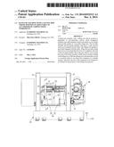
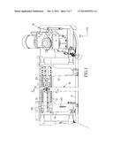
[0014] FIG. 2 is a plan view of a band saw machine with a lifting rod whose position is adjustable to accommodate various sized workpieces in accordance with the present invention;
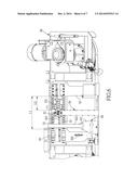
[0015] FIG. 3 is a plan view of a part of the band saw machine with the lifting rod whose position is adjustable to accommodate various sized workpieces in accordance with the present invention;
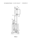
[0016] FIG. 4 is a cross sectional view taken along the line 4-4 of FIG. 2;
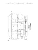
[0017] FIG. 5 is a cross sectional view taken along the line 5-5 of FIG. 3;
[0018] FIG. 6 is an operational view showing the movement of the movable clamp arm of the band saw machine with the lifting rod in accordance with the present invention; and
[0019] FIG. 7 is another operational view showing the state of the band saw machine with the lifting rod in accordance with the present invention, after the movable member and the lifting rod move to a new position.
DETAILED DESCRIPTION OF THE PREFERRED EMBODIMENTS
[0020] The present invention will be clearer from the following description when viewed together with the accompanying drawings, which show, for purpose of illustrations only, the preferred embodiment in accordance with the present invention.
[0021] Referring to FIGS. 2-8, a band saw machine with a lifting rod whose position is adjustable to accommodate various sized workpieces in accordance with the present invention comprises: a base 20, a saw frame 30, a clamping unit 40, and the lifting rod 50.
[0022] The base 20 is provided with two lifting rods 21.
[0023] The saw frame 30 is disposed on the two lifting rods 21 and capable of moving up and down with respect to the lifting rods 21. Around the saw frame 30 is provided a rotatable band saw 31. On a surface of the saw frame 30 is fixed a fixing member 32 with one end contacting the band saw 31. On the fixing member 32 is fixed a stationary rack 321 which extends along a first direction D1, and a direction which is perpendicular to the first direction D1 is defined as a second direction D2. On the saw frame 30 is further provided a pair of rails 33, and each of the rails 33 extends along the first direction D1 and is provided with a movable member 34 whose one end has two sliders 341 movably sleeved onto the rails 33, so that the movable member 34 are disposed on the rails 33 and movable in the first direction D1. Another end of each of the movable members comes into contact with the band saw 31, and the band saw 31 moves, it can drive the movable member 34 to move. On each of the movable members 34 is fixed a bearing 342 and a movable rack 343 which extends in the first direction D1 and is located at a different position in the second direction D2 with respect to the stationary rack 321, namely, the movable rack 343 is in parallel with the stationary rack 321. On another surface of the saw frame 30 is provided another rail 35.
[0024] The clamping unit 40 is located beside the saw frame 30 and comprises a stationary clamp arm 41 and a movable clamp arm 42. The stationary clamp arm 41 is abutted against the fixing member 32. The movable clamp arm 42 is movable along the first direction D1 and includes a clamp portion 421 on which being formed a stop rod 422. The workpiece is to be clamped between the clamp portion 421 and the stationary clamp arm 41. The stop rod 422 of the movable clamp arm 42 extends along the second direction D2. When the movable clamp arm 42 moves to a furthest position from the stationary clamp arm 41, the stop rod 422 of the movable clamp arm 42 will be abutted against the bearing 342 of the movable member 34, namely, the movable member 34 uses the bearing 342 to stop against the movable member 34, so as to restrict the travel of the movable member 34.
[0025] On one surface of the lifting rod 50 is disposed a slide block 51, and on another surface of the lifting rod 50 is pivotally provided a gear shaft 52. The slide block 51 is movably sleeved onto the rail 35 of the saw frame 30, so that the lifting rod 50 is disposed on the saw frame 30 and movable along the first direction D1, in such a manner that the lifting rod 50 is located between the fixing member 32 and the movable member 34, the gear shaft 52 is located between the stationary rack 321 and the movable rack 343, and the gear shaft 52 is engaged with the stationary rack 321 and the movable rack 343. When the movable member 34 moves, the movable rack 343 will drive the gear shaft 52 to move along the stationary rack 321, and cause the position of the lifting rod 50 to change.
[0026] When the movable clamp arm 42 of the clamping unit 40 is located at a furthest position from the stationary clamp arm 41, as shown in FIG. 2, the space between the movable clamp arm 42 and the stationary clamp arm 41 is provided for clamping a workpiece, and the lifting rod 50 is located at the center of the workpiece, so that it can conveniently and precisely detect the workpiece. At this moment, there are a first initial distance L1 between the fixing member 32 and the movable member 34, and a second initial distance L2 between the lifting rod 50 and the fixing member 32.
[0027] When the workpiece to be clamped is relatively small, as shown in FIG. 6, the movable clamp arm 42 can be controlled to move toward the stationary clamp arm 41, so that the space between the movable clamp arm 42 and the stationary clamp arm 41 is narrowed down to clamp a small workpiece. At this moment, the movable clamp arm 42 also moves away from the bearing 342 of the movable member 34, and then the band saw 31 can be switched on. When the band saw 31 rotates, the movable member 34 will be driven by the band saw 31 to move toward the movable clamp arm 42, and the end point of the travel length of the movable member 34 is where the bearing 342 is stopped against the stop rod 422 of the movable clamp arm 42.
[0028] When the movable member 34 is moving, the movable rack 343 also moves toward the stationary clamp arm 41, meanwhile, the gear shaft 52 engaged with the movable rack 343 is rotated by the movable rack 343, which causes linear movement of the gear shaft 52 along the stationary rack 321. When the gear shaft 52 linearly moves along the stationary rack 321, the lifting rod 50 will also be caused to move toward the fixing member 32, as shown in FIG. 7. Therefore, the first initial distance L1 between the fixing member 32 and the movable member 34 is narrowed down to a first clamping distance 11, and the second initial distance L2 between the lifting rod 50 and the fixing member 32 is also narrowed down to a second clamping distance 12. By such arrangements, the movable clamp arm 42 can be moved to clamp small workpiece, and when the movable clamp arm 42 moves, the movable member 34 and the lifting rod 50 will also move along with it, as shown in FIG. 7, which ensures that the lifting rod 50 keeps staying at a position where it can detect the workpiece in a reliable manner.
[0029] In general, the band saw machine with the lifting rod whose position is adjustable to accommodate various sized workpieces in accordance with the present invention is simply structured, wherein the movable clamp arm 42 can be moved to clamp different sized workpieces, meanwhile, the lifting rod 50 is automatically moved to a position where it can detect the workpiece in a reliable manner. Therefore, the size of the workpiece to be clamped by the band saw machine in accordance with the present invention is not limited by the position of the lifting rod 50 anymore, namely, the present invention is capable of dealing with different workpieces over a broader range of size.
[0030] While we have shown and described various embodiments in accordance with the present invention, it is clear to those skilled in the art that further embodiments may be made without departing from the scope of the present invention.
User Contributions:
Comment about this patent or add new information about this topic:
Images included with this patent application:
 |  |
 |  |
 |  |
 |  |
| New patent applications in this class: | |
| Date | Title |
|---|---|
| 2013-03-07 | Workpiece clamp for miter saw |
| 2012-03-08 | Vise clamping tool for table-type circular sawing machine |
| 2012-01-12 | All in one window covering cutdown machine |
| 2011-06-09 | Log rest |
| 2009-11-26 | Hold-down device for plate shears |
| New patent applications from these inventors: | |
| Date | Title |
|---|---|
| 2014-08-07 | Double-saw band saw machine and a method for using the same |
| 2013-11-28 | Cutting-angle adjustable bandsaw |
| 2013-05-09 | Double-acting pipe cutting band saw apparatus and method for using the same |
| Top Inventors for class "Cutting" | |
| Rank | Inventor's name |
|---|---|
| 1 | Stephen F. Gass |
| 2 | Stephen F. Gass |
| 3 | Toshiyuki Kani |
| 4 | Andrew Frolov |
| 5 | J. David Fulmer |