Patent application title: Clip on car visor extension
Inventors:
Marlan Dean Goodwin (Upland, CA, US)
Leticia Martha Goodwin (Upland, CA, US)
IPC8 Class: AB60J302FI
USPC Class:
296 976
Class name: Bodies glare screen or visor having detachable auxiliary visor or glare screen cooperating therewith
Publication date: 2014-08-28
Patent application number: 20140239665
Abstract:
A clip on car visor extension for use on a vehicle's existing sun visor,
effectively blocks out sunrays which the visor itself is not capable of
blocking on its' own. The clip on car visor extension is made up of a
clip member and a glare reducing sheet element, rotatably fastened on the
clip member. The clip member has two elongated legs joined at the closed
end by a connecting leg. The glare reducing sheet element is preferably
rectangular shaped.
The clip on car visor extension can be moved laterally or horizontally on
the vehicles sun visor as needed by moving the clip member and radially
rotating the glare reducing sheet element to an angle as needed depending
on the user's position and sun's position in the sky.Claims:
1. A clip on car visor extension for use on a front automobile sun visor
wherein the front automobile sun visor only partially blocks out sun rays
shining through a front windshield and adjacent side windows of the motor
vehicle with unblocked sun rays shining into the frontal and peripheral
view of an occupant in the motor vehicle's front seat, said clip on car
visor extension comprising: (a) a clip member for adjustably mounting on
the front automobile sun visor of the motor vehicle, said clip member
having two elongated legs and a connecting leg wherein the elongated legs
are joined at closed ends as best seen in FIG. 3, to the connecting leg
and further wherein at least one of the two elongated legs have a distal
end with a grabber means for gripping the front automobile sun visor; and
(b) a glare reducing composite sheet element adjustably positioned on the
connecting leg of the clip member, said glare reducing composite sheet
element having a central hole adjacent to lateral edge area; and (c) a
rivet like fastener that adjoins the surfaces of clip member and glare
reducing composite sheet to each other and when properly attached,
permits for radial rotation and holding in place by torque friction said
glare reducing composite sheet element on the clip member to a desired
angle whereby unwanted sun rays are blocked out by the glare reducing
composite sheet element by horizontally or laterally positioning the clip
member on the front automobile sun visor and by rotationally positioning
the glare reducing composite sheet element on the clip member.
2. The clip on car visor extension of claim 1 wherein the two elongated legs of the clip member each have an open end with an inside face and further wherein the grabber means a set of ridges extending substantially horizontally across each inside face at the open ends of the elongated legs.
3. The clip on car visor extension of claim 1 wherein the two elongated legs of the clip member are spaced from about 0.25 inches to about 0.75 inches apart at the closed ends for vertically adjustable positioning on the motor vehicle's automobile sun visor.
4. The clip on car visor extension of claim 1 wherein each of the two elongated legs of the clip member ranges from about two inches to about four inches in length.
5. The clip on car visor extension of claim 1 wherein the glare reducing composite sheet element is generally rectangular shaped with a width of about three inches to about eight inches and a height of about three inches to about five inches.
6. The clip on car visor extension of claim 1 further wherein the glare reducing composite sheet element is tinted with a colorant.
7. The clip on car visor extension of claim 1 further wherein the glare reducing composite sheet element has a width of from about three inches to about eight inches and a height of from about three inches to about five inches.
8. The clip on car visor extension of claim 1 further wherein the glare reducing composite sheet element is opaque.
Description:
CROSS REFERENCE TO RELATED APPLICATIONS
[0001] Provisional Patent Application No. 61/603,280
[0002] EFS ID 12159973
[0003] Filing Date Feb. 25, 2012
[0004] Confirmation No. 5517
STATEMENT REGARDING FEDERALLY SPONSORED RESEARCH OR DEVELOPMENT
[0005] "Not Applicable"
REFERENCE TO SEQUENCE LISTING, A TABLE, OR A COMPUTER PROGRAM LISTING COMPACT DISC APPENDIX
[0006] "Not Applicable"
BACKGROUND OF THE INVENTION
[0007] This device relates to an extension of an existing automobile sun visor. Sun visors made by automobile manufacturers protect the driver from sun glare when the sun is directly in front of him or her. If the sun is to the side of the driver or front seat passenger, positioning the existing sun visor on the side, adjacent to the user, does not always prevent the user from being irritated by the sun. If the sun's rays come from the side of the user into the car, the user can turn the standard visor to the adjacent side window, but since very few roads are straight as an arrow, as the vehicle turns while driving, the angle of incidence of the light also changes as his directionality changes. Thus he is susceptible to sun glare from the now unprotected side area. Sun visors are a fairly uniform size and since they are opaque they cannot be so wide that they would block the rear view mirror or extended too far downward since they would then block the vision of the driver or front seat passenger. Consequently the sun glare often affects the user's eyes below the lowest position of the visor and the uppermost rear corner area of the side window such that the visor offers no sun protection to the user unless he strains upward or forward. There are a few characteristics which a successful sun shield product must possess. It must be universally adaptable for use on all or at least most all motor vehicle models. The product must be easily accessed by the user and readily adjusted to the particular condition. The product also must be inexpensive. To date, no product intended for use in blocking out sun glare in motor vehicles has been developed which truly has all the aforementioned characteristics. The clip on car visor extension is readily positioned on the motor vehicles sun visor and adjusted to a use position as needed. It is adaptable for installation on most vehicle models and is beneficial to drivers and front seat passengers of all heights. There is no sun visor extension device known in prior art which can be attached to a standard vehicle sun visor and extended by swiveling outward, which may be utilized to provide the user (driver or front seat passenger) from sun glare coming from the uppermost rear corner area of the side door window. Many attempts have been made to create a device which attaches to the vehicle sun visor to solve what has proven to be a longstanding problem such as the following prior art:
[0008] U.S. Pat. No. 4,580,829 to Matheopoulos discloses an adjustable bi-directional vehicle visor pivotally mounted to the vehicle adjacent the windshield allowing horizontal rotation between a stored position and an operating position. The devise consists of an opaque first visor and a second transparent tinted visor which overlays the first visor when it is in the stored position and is pivotable about the first visor when in operating position to allow shielding both at the front and sides simultaneously. The second visor may also be positioned in parallel alignment below the first visor. In this construction, the visor is incapable of providing additional glare protection axially from the visor.
[0009] U.S. Pat. No. 4,728,142 and U.S. Pat. No. 4,828,314 to Gavagan discusses a visor assembly having one or more retractable glare screens integrated with the visor so as to be extended and retracted from the visor as required. The glare screens are guided for retracted movement by slot followers travelling in elongated guide slots formed in the visor center board member. In this configuration, a slot follower is required to limit travel of the blades. In addition, such configuration is intended for use with a visor having a center board member.
[0010] U.S. Pat. No. 4,792,176 to Karford discloses a visor extension unit which is adapted for releasable attachment to a conventional visor of a motor vehicle. The device includes a support frame having opposed surfaces and means for attaching one of the surfaces to the body of the visor. A pair of guide passages at opposite ends of the unit enable the visor panel to be manually moved in a horizontal direction extending either from the left side or right side based on the location of the sun. In this construction, no limiting means exists for preventing the visor from being pulled completely outside the visor.
[0011] U.S. Pat. No. 4,824,161 to Lee discloses an automobile visor having a vertical series of pivotally connected shield plates which are suspended from a horizontal hanging portion of a hanging rod portably mounted on a roof panel. The shield plates are in horizontal alignment when unfolded, each containing a side slot having a side plate horizontally extendable therefrom. In this construction, it is necessary to unfold at least one plate and then extend the insert horizontally to protect against glare. There are no limiting means for retaining the blade within one of the connected shield plates.
[0012] U.S. Pat. No. 4,323,275 to Lutz discloses a housing having an auxiliary visor connected at two locations to the existing visor originally mounted on the motor vehicle. Limiting stops having a lug sliding in an associated slot is used to prevent complete withdrawal of the auxiliary visors. In this construction, modification of the original visor is required to properly mount the housing containing the auxiliary visors. Furthermore, the mounting of the additional housing increases the thickness of the visor, thereby interfering with the positioning of the visor in the stored position.
BRIEF SUMMARY OF THE INVENTION
[0013] The object of the present device is to provide the user (driver or front seat passenger) with protection from glare coming from the uppermost rear corner area of the side window. It is also an object of the clip on car visor extension to provide such protection which is simple and convenient for the user to use and can be added on to any model of existing sun visors at any time. The clip on car visor extension is a device that can be semi permanently attached to the original vehicle visor when it is positioned adjacent to the side window. Once the device is clipped onto the existing visor at the far end of the original vehicle visor, the device can be extended/swiveled outward so that it shades the user from the glare of the sun. When not in use the visor sheet element can easily be swiveled into a stored position that is completely out of the way and does not interfere with the normal use of original vehicle's sun visor. The materials used for manufacturing result in a lightweight, multi-positional device which attaches to most existing vehicle sun visors. Proper use of the existing vehicle sun visor and the clip on car visor extension device can significantly prevent problems associated with sun glare such as eye fatigue, eye discomfort and vision impairment. Bright light glare from another vehicle can also be alleviated by use of the clip on car visor extension. Normal operation of the vehicle's visor is not affected.
BRIEF DESCRIPTION OF THE SEVERAL VIEWS OF THE DRAWING
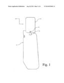
[0014] FIG. 1 is an environmental view of the device mounted on the sun visor of a motor vehicle.
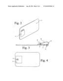
[0015] FIG. 2 is a front perspective view of the device
[0016] FIG. 3 is a top plan view of the device illustrated in FIG. 2.
[0017] FIG. 4 is a front elevation view of the device illustrated in FIG. 2.
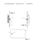
[0018] FIG. 5 is a right elevation view of the device illustrated in FIG. 2.
[0019] FIG. 6 is a left elevation view of the device illustrated in FIG. 2.
[0020] FIG. 7 is a rear elevation view of the device illustrated in FIG. 2.
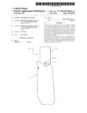
[0021] FIG. 8 is an environmental view of the device mounted on the sun visor of a motor vehicle
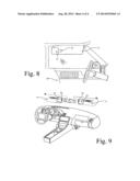
[0022] FIG. 9 is an environmental view of the device mounted on the sun visor of a motor vehicle
DETAILED DESCRIPTION OF THE INVENTION
[0023] The device is intended for use on motor vehicles of all types, including, vans, pickup trucks and transport trucks. The device is mounted at least on the motor vehicle's driver side or front passenger side sun visor.
[0024] With reference to FIG. 1, the device 10 is mounted on the driver's side (or front passenger's side) sun visor 11 of a motor vehicle. As best seen on FIG. 1, the clip on car visor extension 10 comprises a clip member 12 and a glare reducing sheet element 13 and a rivet like fastener 14. Each of the components of the device is described in detail in the following paragraphs and with particular references to the drawings. A manner of use of the device is also described.
[0025] The clip member 12 of the device 10 is best seen in FIGS. 3 thru 5. The clip member 12 is for semi permanently mounting to the motor vehicles sun visor and for holding the glare reducing sheet element 13 in a manner which permits position adjustability to block out glaring light. Two elongated legs 20 and 21 are joined at their closed ends by a connecting leg 22. The resultant clip member has a generally U-shape configuration when viewed from the side as seen in FIG. 3.
[0026] As should be apparent, the clip member's configuration permits a free end of the clip member to be forced onto the motor vehicle's sun visor, normally until the top of the connecting leg contacts a lateral edge of the visor. Each elongated leg 20 and 21, as measured from a point where a lower end meets the top of the connecting leg to an extremity of an upper end ranges from about two inches to about four inches.
[0027] The upper end of at least one elongated leg has rows of ridges which act as a grabber and aid in holding the clip member to the sun visor. As evident in FIGS. 3 and 4, the grabber means a set of substantially horizontally extending ridges 24 and 25 on an inside face of the open end of each leg. The ridges 24 and 25 extend substantially across the elongated legs 20 and 21, respectively, and are opposed to one another. One set of ridges grabs a front surface of the sun visor and the opposed second set of ridges grabs the back surface of the sun visor.
[0028] Again with reference to FIG. 3, the elongated legs of the clip member 12 are capable of being flexed outwardly to 0.75 inch initially to position the clip member onto the sun visor and then, upon release of a spreading force, resume their natural position. There is sufficient resiliency in the clip member to accommodate different thicknesses of automobile sun visors and to accommodate a mirror or other object often built into an automobile's sun visor by the vehicle's manufacturer. A friction fit onto the vehicle's sun visor as aided by the horizontally extending ridges acts to semi-permanently hold the clip member in place. The holding power of the clip member is adequate to withstand normal bumps and vibrations encountered on the road.
[0029] The connecting leg 22 holds the elongated legs 20 and 21 at a spaced relationship approximately equal to or slightly less than the thickness of the vehicle's sun visor, i.e. from about 0.25 inches to about 0.50 inches.
[0030] The clip member 12 is preferably made of a composite material in an injection molding operation for cost reasons. It can also be made of other materials such as a metal and made by other production techniques such as machining or extrusion molding.
[0031] With reference to FIGS. 1, 4 and 7, the glare reducing composite sheet element 13 is flat with a generally rectangular shape and further has a thin cross section. The sheet element can have other geometric shapes which are conducive to creating a substantial sun glare blocking function. Preferably, the glare reducing composite sheet element 13 ranges from about four inches to about eight inches in width and about three inches to about five inches in height. It has a thickness of less than about 0.50 inches, preferably from about 10 mil to about 30 mil.
[0032] As best seen in FIGS. 4 and 7, the glare reducing composite sheet element 13 has a hole centrally located 35 adjacent to a lateral edge area for attachment purposes to the clip member 12. As apparent in FIG. 3, when the glare reducing composite sheet element 13 is properly fastened by a rivet 14 or similar fastener to the clip member 12, the composite sheet frictionally adjoins onto the clip member to allow a rotational movement of the sheet element 13 about the axis 15 of the rivet 14 that is now joined to the clip member.
[0033] The sheet element 13 is fastened to the clip member 12 and when not in use, it can simply be rotated about the connecting fastener 14 of the clip member until it is flat against the vehicle's sun visor. As best seen in FIG. 8, when needed to block out sun glare, the sheet element 13 is rotated about the fastener 14 until a sheet element angle is reached which blocks out the sun glare, yet permits maximum road view. The opposed surfaces of the clip member and the sheet element frictionally engage walls of the two surfaces such that the sheet element angle is retained once reached with minimal torque.
[0034] The glare reducing composite sheet element 13 is preferably translucent to allow the vehicle's driver or front seat 16 passenger to see through the sheet element for safe driving purposes, though it could be opaque as well. The composite sheet element 13 can be made by injection molding a polycarbonate resin to obtain the sheet element or by die cutting the sheet element from sheet goods. The resin used to make the sheet element of the sheet is preferably made glare reducing by tinting with a colorant having any desired color shade such that sun glare is significantly reduced, but objects are still visible through the sheet element.
[0035] In use, the clip member is forced onto the automobile sun visor of the vehicle. The user can now slide the clip member laterally left or right or horizontally up and down until the glare reducing composite sheet element is in position to block out unwanted sun rays. A final adjustment is made by rotating the glare reducing composite sheet element rotationally about the connecting fastener 14 axis 15 until the sun rays are fully blocked out and maximum road viewing is retained. Because only one clip member is needed with the sun shield, the user can adjust the clip member's position and the glare reducing composite sheet's position with one hand.
[0036] The automobile sun visor can be approximately positioned and the clip on car visor extension precisely positioned to accomplish its function. As best seen in FIG. 9, when no longer needed because of a change of travel direction or sun position, the glare reducing composite sheet element 13 is rotated until it is flat with the vehicle's sun visor 11.
[0037] Having described the device in its preferred embodiment, it should be clear that modifications can be made without departing from the spirit of the device. It is not intended that the words used to describe the device nor the drawings illustrating the same be limiting on the device. It is intended that the device only be limited by the scope of the appended claims.
User Contributions:
Comment about this patent or add new information about this topic:
Images included with this patent application:
 |  |
 |  |
 |
| Similar patent applications: | |
| Date | Title |
|---|---|
| 2014-09-18 | Breakaway visor retention check |
| 2009-05-14 | Corner rail extrusion |
| 2010-09-02 | Flip open sun visor |
| 2012-08-23 | Visorxtension/visorx/vx |
| New patent applications in this class: | |
| Date | Title |
|---|---|
| 2015-11-19 | Extruded visor for open-roof vehicles |
| 2014-09-25 | Adjustable sun visor system for vehicle windshield and side window |
| 2014-04-17 | Compact poldable automobile sun-shield which is semi-permanently installed |
| 2013-12-05 | Visor extension device |
| 2013-11-07 | Shade device |
| Top Inventors for class "Land vehicles: bodies and tops" | |
| Rank | Inventor's name |
|---|---|
| 1 | Udo Mildner |
| 2 | Lothar Teske |
| 3 | Marcel Johan Christiaan Nellen |
| 4 | Gm Global Technology Operations Llc |
| 5 | Thomas Scott Breidenbach |