Patent application title: DISPENSING MECHANISM OF VENDING MACHINE
Inventors:
Chen-Liang Geng (Shenzhen, CN)
Assignees:
HON HAI PRECISION INDUSTRY CO., LTD.
HONG FU JIN PRECISION INDUSTRY (ShenZhen) CO., LTD.
IPC8 Class: AG07F1124FI
USPC Class:
221277
Class name: Article dispensing with discharge assistant rotary
Publication date: 2014-07-03
Patent application number: 20140183217
Abstract:
A dispensing mechanism for a vending machine includes a first side plate,
a second side plate, a bottom plate, and a rotary baffle. The second side
plate and the first side plate cooperatively define a vertical space for
accommodating items. The bottom plate is connected to a bottom edge of
the first side plate and supports the items. The rotary baffle is located
above the bottom plate and is rotatable about a horizontal axis. When
item delivery is required, the rotary baffle moves through a
predetermined angle to allow one item to be pushed through the rotary
baffle and out by the weight of the remaining items in the vertical
stack, which allows the delivery of purchased items individually.Claims:
1. A dispensing mechanism of a vending machine, comprising: a first side
plate; a second side plate parallel to the first side plate, the second
side plate and the first side plate cooperatively defining a vertical
space configured for accommodating items; a bottom plate connected to a
bottom edge of the first side plate and configured to support the items;
and a rotary baffle located above the bottom plate, the rotary baffle
being rotatable about a horizontal axis, wherein the rotary baffle is
configured to allow one of the items to move away from the bottom plate
by rotating a predetermined angle at a time.
2. The dispensing mechanism of claim 1, wherein an obtuse angle is defined between the bottom plate and the first side plate.
3. The dispensing mechanism of claim 2, wherein the bottom plate is spaced from a bottom edge of the second side plate and an interspace is defined between the bottom plate and the bottom edge of the second side plate.
4. The dispensing mechanism of claim 3, wherein the rotary baffle defines a plurality of latching slots, when the rotary baffle is at rest, one of the plurality of latching slots latches one of the items and prevents the item from moving away from the bottom plate.
5. The dispensing mechanism of claim 4, wherein each of the plurality of latching slots is V-shaped.
6. The dispensing mechanism of claim 5, wherein a cross section of the rotary baffle is cross-shaped, the rotary baffle is configured to drive one of the items to move away from the bottom plate by rotating every 90 degrees.
7. The dispensing mechanism of claim 6, wherein an angle between the bottom plate and a horizontal plane is smaller than 30 degrees.
8. The dispensing mechanism of claim 6, wherein a distance between the first side plate and the second side plate is substantially the same as a width of one of the items.
9. The dispensing mechanism of claim 6, wherein a distance between the bottom plate and the bottom edge of the second side plate is substantially the same as a height of one of the items.
10. The dispensing mechanism of claim 6, wherein the bottom plate and the first side plate cooperatively form an L-shaped structure.
11. A dispensing mechanism of a vending machine, comprising: a first side plate; a second side plate parallel to the first side plate, the second side plate and with the first side plate cooperatively defining a vertical space configured for accommodating items; a bottom plate extending obliquely and downwards from a bottom edge of the first side plate, the bottom plate being configured to support the items; and a rotary baffle located above the bottom plate, the rotary baffle being rotatable about a horizontal axis, wherein when the rotary baffle is at rest, the rotary baffle retains the items and prevents the items from moving away from the bottom plate, when the rotary baffle rotates a predetermined angle, the rotary baffle allows one of the items to move away from the bottom plate.
12. The dispensing mechanism of claim 11, wherein an obtuse angle is defined between the bottom plate and the first side plate.
13. The dispensing mechanism of claim 12, wherein the bottom plate is spaced from a bottom edge of the second side plate and an interspace is defined between the bottom plate and the bottom edge of the second side plate.
14. The dispensing mechanism of claim 13, wherein the rotary baffle defines a plurality of latching slots, when the rotary baffle is at rest, one of the plurality of latching slots latches one of the items and prevents the item from moving away from the bottom plate.
15. The dispensing mechanism of claim 14, wherein each of the plurality of latching slots is V-shaped.
16. The dispensing mechanism of claim 15, wherein a cross section of the rotary baffle is cross-shaped, the rotary baffle is configured to drive one of the items to move away from the bottom plate by rotating every 90 degrees.
17. The dispensing mechanism of claim 16, wherein an angle between the bottom plate and a horizontal plane is smaller than 30 degrees.
18. The dispensing mechanism of claim 16, wherein a distance between the first side plate and the second side plate is substantially the same as a width of one of the items.
19. The dispensing mechanism of claim 16, wherein a distance between the bottom plate and the bottom edge of the second side plate is substantially the same as a height of one of the items.
20. The dispensing mechanism of claim 16, wherein the bottom plate and the first side plate cooperatively form an L-shaped structure.
Description:
REFERENCE TO RELATED APPLICATIONS
[0001] This application claims all benefits accruing under 35 U.S.C. §119 from China Patent Application No. 201210582015.4 filed on Dec. 28, 2012 in the State Intellectual Property Office of China, the contents of the China Application are hereby incorporated by reference.
BACKGROUND
[0002] 1. Technical Field
[0003] The present disclosure generally relates to vending machines, and particularly relates to a dispensing mechanism of a vending machine.
[0004] 2. Description of Related Art
[0005] Vending machines have been in common use for purchasing a variety of items such as snacks, beverages, alcohol, cigarettes, lottery tickets, cologne, consumer products and even gold and gems. A vending machine typically includes a dispensing mechanism for dispensing items to customers after the customers insert currency or credit into the vending machines. However, the conventional dispensing mechanism is inflexible and is not able to handle increasing demands.
[0006] Therefore, there is room for improvement within the art.
BRIEF DESCRIPTION OF THE DRAWINGS
[0007] Many aspects of the embodiments can be better understood with reference to the following drawings. The components in the drawings are not necessarily drawn to scale, the emphasis instead being placed upon clearly illustrating the principles of the embodiments. Moreover, in the drawings, like reference numerals designate corresponding parts throughout the several views.
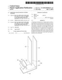
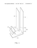
[0008] FIG. 1 is an exploded, isometric view of an embodiment of a dispensing mechanism of a vending machine.
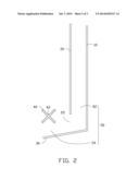
[0009] FIG. 2 is a cross-sectional view of the dispensing mechanism of FIG. 1.
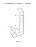
[0010] FIG. 3 is similar to FIG. 1, showing the dispensing mechanism loaded with items.
DETAILED DESCRIPTION
[0011] The disclosure is illustrated by way of example and not by way of limitation in the figures of the accompanying drawings in which like references indicate similar elements. It should be noted that references to "an" or "one" embodiment in this disclosure are not necessarily to the same embodiment, and such references mean "at least one."
[0012] FIGS. 1 and 2 show an embodiment of a dispensing mechanism of a vending machine. The dispensing machine includes a first side plate 10, a second side plate 20, a bottom plate 30 and a rotary baffle 40.
[0013] The second side plate 20 is parallel to the first side plate 10. The second side plate 20 together with the first side plate 10 defines a vertical space 52 for accommodating items. A distance between the first side plate 10 and the second side plate 20 is substantially the same as a width of a item. A length of the second side plate 20 is smaller than that of the first side plate 10.
[0014] The bottom plate 30 is connected to a bottom edge of the first side plate 10. The bottom plate 30 extends obliquely and downwards from the bottom edge of the first side plate 10. The bottom plate 30 supports items. The bottom plate 30 together with the first side plate 10 forms an L-shaped structure. An obtuse angle is defined between the bottom plate 30 and the first side plate 10. In some embodiments, an angle between the bottom plate 30 and a horizontal plane is smaller than 30 degrees.
[0015] The bottom plate 30 is spaced from a bottom edge of the second side plate 20. An interspace 25 is defined between the bottom plate 30 and the bottom edge of the second side plate 20. A distance between the bottom plate 30 and the bottom edge of the second side plate 20 is substantially the same as a vertical height of an item.
[0016] The rotary baffle 40 is located above the bottom plate 30. The rotary baffle 40 is rotatable about a horizontal axis. The rotary baffle 40 defines a plurality of latching slots 42. Each of the plurality of latching slots 42 forms the shape of a V.
[0017] In one embodiment, as shown in FIG. 2, a cross section of the rotary baffle 40 is cross-shaped. The interior angle of each latching slot is then 90 degrees.
[0018] A horizontal space 54 above the bottom plate 30 and the vertical space 52 form an L-shaped aisle 50. The items may move along the L-shaped aisle 50 and drop down from the left edge of the bottom plate 30.
[0019] FIG. 3 shows that, in use, the dispensing mechanism is loaded with items. Some of the items are supported by the bottom plate 30 and others are accommodated in the vertical space 52. When the rotary baffle 40 is at rest, one of the plurality of latching slots 42 receives a item and prevents the items from moving away from the bottom plate 30. When the rotary baffle 40 rotates a predetermined angle (e.g. 90 degrees), the rotary baffle 40 allows one item to move away from the bottom plate 30. When a item has moved away from the bottom plate 30, the other items move down in the vertical space 52 by gravity and fill the position of the item which has moved away.
[0020] It is to be understood, however, that even though numerous characteristics and advantages have been set forth in the foregoing description of embodiments, together with details of the structures and functions of the embodiments, the disclosure is illustrative only and changes may be made in detail, especially in the matters of shape, size, and arrangement of parts within the principles of the disclosure to the full extent indicated by the broad general meaning of the terms in which the appended claims are expressed.
User Contributions:
Comment about this patent or add new information about this topic:
| People who visited this patent also read: | |
| Patent application number | Title |
|---|---|
| 20200413122 | TELEVISION USER INTERFACE |
| 20200413121 | SMART CONTROL DEVICE, METHOD FOR IMPLEMENTING SMART CONTROL DEVICE, AND SMART TV |
| 20200413120 | METHOD OF CONTROLLING THE SHARING OF VIDEOS AND ELECTRONIC DEVICE ADAPTED THERETO |
| 20200413119 | CONTROL DEVICE, CONTROL METHOD, ELECTRONIC DEVICE, AND PROGRAM |
| 20200413118 | OPTIMIZING A RESOURCE USAGE PER CONVERSION FOR OFFSITE CONTENT |
Images included with this patent application:
 |  |
 |  |
| Similar patent applications: | |
| Date | Title |
|---|---|
| 2014-07-03 | Goods channel for vending machine |
| 2014-07-03 | Automatic vending machine |
| 2014-07-10 | Automatic vending machine |
| 2014-07-31 | Dispenser and stack of sheet products |
| 2014-08-07 | Automatic vending machine with buffering device |
| New patent applications in this class: | |
| Date | Title |
|---|---|
| 2016-06-02 | Medicine cassette and medicine feeding apparatus |
| 2016-04-07 | Anti-jam dispenser |
| 2015-03-26 | Tablet cassette |
| 2015-03-26 | Tablet cassette |
| 2015-01-22 | Dispensing device in vending machine |
| Top Inventors for class "Article dispensing" | |
| Rank | Inventor's name |
|---|---|
| 1 | Yun-Lung Chen |
| 2 | Aaron L. Bates |
| 3 | Richard D. Michelli |
| 4 | Jun-Ho Kim |
| 5 | Bryan Patrick Farnsworth |