Patent application title: BUBBLE BLOWER
Inventors:
Shau-Chi Lin (Xindian City, TW)
IPC8 Class: AA63H3328FI
USPC Class:
446 15
Class name: Amusement devices: toys having means for forming transitory bubble
Publication date: 2014-01-23
Patent application number: 20140024281
Abstract:
A bubble blower includes an open frame-shaped bubble blower body defining
a main solution-retaining portion, a peripheral rib extending around the
main solution-retaining portion and a main passage between the main
solution-retaining portion and the peripheral rib, and bubble-blowing
rings spaced along an inside wall of the open frame-shaped bubble blower
body each defining an inner solution-retaining portion, an outer
solution-retaining portion connected with the main solution-retaining
portion of the bubble blower body, a sub passage between the inner
solution-retaining portion and the outer solution-retaining portion in
fluid communication with the main passage of the bubble blower body to
form a solution supply passage.Claims:
1. A bubble blower, comprising: a bubble blower body in form of an open
frame, said bubble blower body comprising an opening and a main
solution-retaining portion extending around said opening; and a
bubble-blowing rings respectively extended from an inside wall of said
bubble blower body and suspending in said opening of said bubble blower
body, each said bubble-blowing ring comprising a center opening, an inner
solution-retaining portion extending around said center opening, and an
outer solution-retaining portion extending around an outside wall thereof
and suspending in the opening of said bubble blower body, the outer
solution-retaining portions of said bubble-blowing rings being connected
with said solution-retaining portion to form an enclosed
solution-retaining loop.
2. The bubble blower as claimed in claim 1, wherein said bubble blower body further comprises a peripheral rib extending around said main solution-retaining portion, and a main passage defined between said main solution-retaining portion and said peripheral rib; each said bubble-blowing ring further comprises a sub passage defined between the inner solution-retaining portion and outer solution-retaining portion thereof, the sub passages of said bubble-blowing rings being kept in fluid communication with said main passage of said bubble blower body to form a solution supply passage.
Description:
BACKGROUND OF THE INVENTION
[0001] 1. Field of the Invention
[0002] The present invention relates to bubble blowing toys and more particularly, to a bubble blower, which is operable for blowing a large bubble and then multiple small bubbles in a first stage, and capable of giving bubble solution supply for blowing multiple small bubbles in a second stage.
[0003] 2. Description of the Related Art
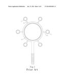
[0004] Referring to FIG. 1, a conventional bubble blower is known comprising a large bubble ring A, a plurality of small bubble rings C spaced around the large bubble ring A, and a plurality of radial ribs B respectively connected between the large bubble ring A and the small bubble rings C. After the bubble blower retains a bubble solution, the user can swing the bubble blower slowly, causing a large bubble to be formed on the large bubble ring A and then moved out of the large bubble ring A. At this time, the user can swing the bubble blower rapidly, causing small bubbles to be formed on the small bubble rings C and then moved out of the respective small bubble rings C. This design of bubble blower can simply retain a limited amount of bubble solution for blowing one large bubble and a limited number of small bubbles once in each bubble solution pickup cycle.
SUMMARY OF THE INVENTION
[0005] The present invention has been accomplished under the circumstances in view. It is the main object of the present invention to provide a bubble blower, which is operable for blowing a large bubble and then multiple small bubbles in a first stage, and capable of giving bubble solution supply for blowing multiple small bubbles in a second stage.
[0006] To achieve this and other objects of the present invention, a bubble blower comprises a bubble blower body defining an opening and a main solution-retaining portion around the opening, and a bubble-blowing rings respectively extended from the inside wall of the bubble blower body in the opening thereof. Each bubble-blowing ring comprises a center opening, an inner solution-retaining portion extending around the center opening, and an outer solution-retaining portion extending around an outside wall thereof and suspending in the opening of the bubble blower body. The outer solution-retaining portions of the bubble-blowing rings are connected with the main solution-retaining portion of the bubble blower body to form an enclosed solution-retaining loop. Further, the bubble blower body comprises a peripheral rib extending around the main solution-retaining portion thereof, and a main passage defined between the main solution-retaining portion and the peripheral rib. Each bubble-blowing ring further comprises a sub passage defined between the inner solution-retaining portion and outer solution-retaining portion thereof. The sub passages of the bubble-blowing rings are kept in fluid communication with the main passage of the bubble blower body to form a solution supply passage.
BRIEF DESCRIPTION OF THE DRAWINGS
[0007] FIG. 1 is a front view of a bubble blower according to the prior art.
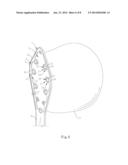
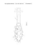
[0008] FIG. 2 is an elevational view of a bubble blower in accordance with the present invention.
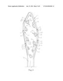
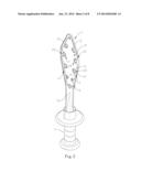
[0009] FIG. 3 is an enlarged view of the bubble blower body of the bubble blower in accordance with the present invention.
[0010] FIG. 4 is a front view of the bubble blower body of the bubble blower in accordance with the present invention.
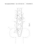
[0011] FIG. 5 is a schematic drawing of the present invention, illustrating the bubble blower body of the bubble blower dipped in a bubble solution in a bubble solution container.
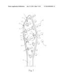
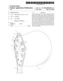
[0012] FIG. 6 is a schematic drawing of the present invention, illustrating the formation of a big bubble at a first stage.
[0013] FIG. 7 is a schematic drawing of the present invention, illustrating the formation of multiple small bubbles at a second stage.
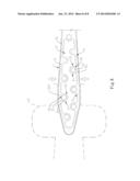
[0014] FIG. 8 is a schematic drawing of an alternate form of the bubble blower in accordance with the present invention.
DETAILED DESCRIPTION OF THE PREFERRED EMBODIMENT
[0015] Referring to FIGS. 2-4, a bubble blower in accordance with the present invention is shown. The bubble blower comprises a bubble blower body 1, a plurality of bubble-blowing rings 2, and a handle 5.
[0016] The bubble blower body 1 is an open frame, comprising an opening 11, a main solution-retaining portion 12 formed of a plurality of teeth 121 spaced along the inside wall of the bubble blower body 1 and facing toward the opening 11, a peripheral rib 13 extending around the main solution-retaining portion 12 and the opening 11, a main passage 14 defined between the main solution-retaining portion 12 and the peripheral rib 13, and a throat 15 located on one side thereof and formed integral with the peripheral rib 13.
[0017] The bubble-blowing rings 2 are respectively extended from the inside wall of the bubble blower body 1 and suspending in the opening 11, each comprising a center opening 21, an inner solution-retaining portion 22 formed of a plurality of teeth 221 spaced along the inside wall thereof and facing toward the center opening 21, an outer solution-retaining portion 23 formed of a plurality of teeth 231 spaced along the outside wall thereof and suspending in the opening 11 of the bubble blower body 1, and a sub passage 24 defined between the inner solution-retaining portion 22 and the outer solution-retaining portion 23.
[0018] Further, the outer solution-retaining portions 23 of the bubble-blowing rings 2 are connected with the main solution-retaining portion 12 of the bubble blower body 1, thereby forming an enclosed solution-retaining loop 3. Further, the sub passages 24 of the bubble-blowing rings 2 are kept in fluid communication with the main passage 14 of the bubble blower body 1, thereby forming a solution supply passage 4.
[0019] Further, the throat 15 of the bubble blower body 1 and the handle 5 are fastened together, forming a bubble blower.
[0020] Referring to FIGS. 5-7, when using the bubble blower, insert the bubble blower body 1 into a bubble solution in a bubble solution container 6, enabling the inner solution-retaining portion 22, the enclosed solution-retaining loop 3 and the solution supply passage 4 to retain the bubble solution. When the user swings the bubble blower in the air, currents of air will enter the bubble blower body 1 to move the retained bubble solution out of the enclosed solution-retaining loop 3, thereby forming a large bubble 7. When the user keeps swinging the bubble blower in the air after formation of the large bubble 7, currents of air will pass through the opening 11 of the bubble blower body 1 and the center opening 21 of each of the bubble-blowing rings 2. At this time, the currents of air that pass through the center opening 21 of each bubble-blowing ring 2 forces the retaining bubble solution out of the inner solution-retaining portion 22 of each bubble-blowing ring 2, forming a respective small bubble 8. Because the bubble solution retained in the enclosed solution-retaining loop 3 has been consumed by the large bubble 7, no further large bubble will be produced at this time. After first time small bubble formation, the bubble solution in the main passage 14 of the bubble blower body 1 will move into the sub passages 24 of the bubble-blowing rings 2 subject to capillary effects, enabling the solution supply passage 4 to supply the bubble solution to the inner solution-retaining portions 22 of the bubble-blowing rings 2 for blowing small bubbles 8 again and again.
[0021] Referring to FIG. 5, when inserting the bubble blower body 1 into the bubble solution container 6, the two opposite lateral sides of the bubble blower body 1 is forced by the narrow mouth of the bubble solution container 6, causing the bubble blower body 1 to elastically contract, and therefore the bubble blower body 1 can be smoothly inserted into the inside of the bubble solution container 6.
[0022] Further, in the aforesaid embodiment, as shown in FIGS. 2-5, the bubble-blowing rings 2 are bilaterally arranged at the inside wall of the bubble blower body 1 inside the opening 11 in a symmetrical manner. Alternatively, as shown in FIG. 8, the bubble-blowing rings 2 can be bilaterally arranged at the inside wall of the bubble blower body 1 inside the opening 11 in a staggered manner.
[0023] In conclusion, the invention provides a bubble blower characterized in that the bubble blower body 1 provides inner solution-retaining portions 22 for blowing additional small bubbles, and a solution supply passage 4 for accommodating bubble solution for giving bubble solution supply to the inner solution-retaining portions 22.
User Contributions:
Comment about this patent or add new information about this topic:
Images included with this patent application:
 |  |
 |  |
 |  |
 |  |
 |
| Similar patent applications: | |
| Date | Title |
|---|---|
| 2014-01-23 | Two-stage bubble blower |
| New patent applications in this class: | |
| Date | Title |
|---|---|
| 2016-06-09 | Bubble making flying disk |
| 2015-12-10 | Bubble generating device |
| 2015-12-03 | Novelty self-contained bath tub aerating toy |
| 2015-10-15 | Motot driven, bubble producing toy |
| 2015-05-14 | Bubble generating apparatus |
| New patent applications from these inventors: | |
| Date | Title |
|---|---|
| 2012-05-31 | Bubble-forming nozzle plate for bubble blower toy |
| Top Inventors for class "Amusement devices: toys" | |
| Rank | Inventor's name |
|---|---|
| 1 | Robert H. Mimlitch, Iii |
| 2 | David Anthony Norman |
| 3 | Michael Nuttall |
| 4 | Stacy Lynn O'Connor |
| 5 | Joel Reagan Carter |