Patent application title: Anode Retainer for Cathodic Corrosion Protection Devices of Foundation Pipes of Offshore Wind Turbines, Foundation Pipe of an Offshore Wind Turbine and Connecting Structure Therebetween, Cathodic Corrosion Protection Device for Foundation Pipes of Offshore Wind Turbines, and Offshore Wind Turbine
Inventors:
Robert Ebert (Adenbuttel Ot Rolfsbuttel, DE)
IPC8 Class: AE02D3106FI
USPC Class:
4052111
Class name: Marine structure or fabrication thereof structure protection corrosion prevention
Publication date: 2012-11-08
Patent application number: 20120282035
Abstract:
The invention relates to an anode retainer for cathodic corrosion
protection apparatuses of foundation pipes of offshore wind turbines,
comprising: a metal cylinder ring having a longitudinal axis and an
outside and an inside, wherein a plurality of positioning devices for
concentrically self-positioning, in particular without tools, and fixing,
in particular in a force-closed manner, the cylinder ring on a foundation
pipe under gravity while interacting with corresponding positioning
projections located on the outside of the foundation pipe is provided on
the inside or the cylinder ring over the circumference, to a foundation
pipe of an offshore wind turbine, characterized in that a plurality of
positioning projections is provided on the outside of said foundation
pipe over a cylinder ring area and a connecting structure therebetween,
to a cathodic corrosion protection device for foundation pipes of
offshore wind turbines, and to an offshore wind turbine having the same.Claims:
1. An anode retainer for a cathodic corrosion protection device of a
foundation pipe of an offshore wind power plant, the foundation pipe
having a foundation pipe outside and positioning projections located on
the foundation pipe outside, said anode retainer comprising: a metallic
cylinder ring, said metallic cylinder ring having a longitudinal axis, a
cylinder ring outside, and a cylinder ring inside, said cylinder ring
inside having a periphery; a plurality of positioning means positioned
around said periphery of said cylinder ring inside; and said positioning
means being positioned for concentric self-positioning and fixing of said
cylinder ring on the foundation pipe under the effect of gravity while
interacting with corresponding positioning projections located on the
foundation pipe outside.
2. The anode retainer of claim 1 wherein said positioning means allow tool-free concentric self-positioning of said cylinder ring on the foundation pipe.
3. The anode retainer of claim 1 wherein said positioning means allow force-locking fixing of said cylinder ring on the foundation pipe.
4. The anode retainer of claim 1 wherein said cylinder ring has a cylinder ring outside, said cylinder ring outside having an essentially non-electrically-conductive coating.
5. The anode retainer of claim 1 wherein said cylinder ring (30) has a cylinder ring outside, said cylinder ring outside having passage holes.
6. The anode retainer of claim 1 wherein said positioning means are formed by guide plates positioned on said cylinder ring inside.
7. The anode retainer of claim 1 wherein said positioning means comprise tapering guide paths.
8. The anode retainer of claim 1 further comprising: said positioning means comprising a plurality of tapering guide paths, said guide paths having narrow ends, said guide paths being positioned on said cylinder ring inside; and a fit for a said corresponding positioning projection on the foundation pipe is positioned at said narrow ends of said guide paths.
9. A foundation pipe of an offshore wind power plant comprising, said foundation pipe comprising: a longitudinal axis: a foundation pipe outside and a cylinder ring region; and a plurality of positioning projections, said positioning projections being positioned on said foundation pipe outside, said positioning projections being further positioned over said cylinder ring region.
10. The foundation pipe of claim 9 wherein said plurality of positioning projections are arranged in a first plane and in a second plane in a longitudinal direction of said foundation pipe.
11. The foundation pipe of claim 9 wherein said positioning projections positioned in a first plane are offset in relation to said positioning projections in a second plane in a peripheral direction.
12. The foundation pipe of claim 9 wherein said at least one of said positioning projections comprises, in said second plane, a stop surface, said stop surface being perpendicular to said longitudinal axis of said foundation pipe.
13. A cathodic corrosion protection device for a foundation pipe of an offshore wind power plant, the foundation pipe having a foundation pipe outside and positioning projections located on the foundation pipe outside, said cathodic corrosion protection device comprising: an anode retainer, said anode retainer having a metallic cylinder ring, said metallic cylinder ring having a longitudinal axis, a cylinder ring outside, and a cylinder ring inside, said cylinder ring inside having a periphery, a plurality of positioning means positioned around said periphery of said cylinder ring inside, and said positioning means being positioned for concentric self-positioning and fixing of said cylinder ring on the foundation pipe under the effect of gravity while interacting with corresponding positioning projections located on the foundation pipe outside; at least one anode arranged on said anode retainer; and a protective current unit, said protective current unit being connected between said at least one anode and the foundation pipe for positive charging of said at least one anode and for negative charging of the foundation pipe.
14. The cathodic corrosion protection device of claim 13, wherein a corrosion state detection device is provided for automatic corrosion state detection of the foundation pipe.
15. The cathodic corrosion protection device of claim 13, wherein said protective current unit provides automatic corrosion state detection, control of said protective current unit being in dependence upon the results of corrosion state detection through said protective current unit.
16. An offshore wind power plant comprising: at least one foundation pipe, said foundation pipe having a foundation pipe outside and positioning projections located on said foundation pipe outside; a cathodic corrosion protection device, said cathodic corrosion protection device having an anode retainer, said anode retainer having a metallic cylinder ring, said metallic cylinder ring having a longitudinal axis, a cylinder ring outside, and a cylinder ring inside, said cylinder ring inside having a periphery, a plurality of positioning means positioned around said periphery of said cylinder ring inside, and said positioning means being positioned for concentric self-positioning and fixing of said cylinder ring on said foundation pipe under the effect of gravity while interacting with corresponding positioning projections located on said foundation pipe outside; at least one anode arranged on at least one said anode retainer; and a protective current unit, said protective current unit being connected between said at least one anode and said foundation pipe for positive charging of said at least one anode and for negative charging of said foundation pipe.
17. The offshore wind power plant of claim 16 further comprising a corrosion state detection device for automatic corrosion state detection of said foundation pipe.
18. The offshore wind power plant of claim 16, wherein said protective current unit provides automatic corrosion state detection, control of said protective current unit being in dependence upon the results of corrosion state detection through said protective current unit.
19. The offshore wind power plant of claim 16, wherein said cathodic corrosion protection device comprises for each said foundation pipe a single anode retainer.
20. The offshore wind power plant of claim 16, wherein said cathodic corrosion protection device comprises for each said foundation pipe a plurality of anode retainers.
21. The offshore wind power plant of claim 16, wherein said cathodic corrosion protection device comprises for each said foundation pipe at least one anode retainer.
22. An offshore wind power plant comprising: an anode retainer and a foundation pipe; said foundation pipe having a foundation pipe outside and positioning projections located on said foundation pipe outside; said anode retainer having a metallic cylinder ring, said metallic cylinder ring having a longitudinal axis, a cylinder ring outside, and a cylinder ring inside, said cylinder ring inside having a periphery; a plurality of positioning means positioned around said periphery of said cylinder ring inside; and said anode retainer being arranged concentrically around said foundation pipe, said positioning projections of said foundation pipe being fixed in said positioning means of said anode retainer.
23. The offshore wind power plant of claim 22 further comprising a connecting structure between said foundation pipe and said anode retainer.
24. The offshore wind power plant of claim 22 wherein said positioning projections of said foundation pipe are fixed in said positioning means of said anode retainer in a force-locking manner.
Description:
BACKGROUND
[0001] The present invention relates to an anode retainer for cathodic corrosion protection devices of foundation pipes of offshore wind power plants, a foundation pipe of an offshore wind power plant, a connecting structure between a foundation pipe, an offshore wind power plant and an anode retainer, a cathodic corrosion protection device for foundation pipes of offshore wind power plants, and an offshore wind power plant with at least one foundation pipe and with a cathodic corrosion protection device.
[0002] An active corrosion protection for foundation pipes is usual in offshore wind power plants. This corrosion protection can be achieved in the form of cathodic corrosion protection with external power supply or with galvanic anodes. For the arrangement of the essential components of an external power supply system, such as anodes, distributor boxes, cables, and reference electrodes, below the water level, clamping rings must be tightened in such a construction under water by divers. Diving works result in very high costs and are highly dependent upon the weather.
SUMMARY
[0003] It is thus an object of the invention to facilitate the installation of a cathodic corrosion protection device in offshore wind power plants without the use of divers.
[0004] According to the invention, this object is achieved according to a first aspect by an anode retainer for cathodic corrosion protection devices of foundation pipes of offshore wind power plants, comprising: a metallic cylinder ring with a longitudinal axis and an outside and an inside, wherein on the inside around the periphery a plurality of positioning devices are provided for, in particular tool-free, concentric self-positioning and, in particular force-locking, fixing of the cylinder ring on a foundation pipe under the effect of gravity while interacting with corresponding positioning projections arranged on the outside of the foundation pipe.
[0005] Furthermore this object is achieved according to a second aspect by a foundation pipe of an offshore wind power plant, characterised in that a plurality of positioning projections are provided on the outside thereof over a cylinder ring region.
[0006] According to a third aspect this object is achieved by a connecting structure between a foundation pipe of an offshore wind power plant and an anode retainer, wherein the anode retainer is arranged concentrically around the foundation pipe and the positioning projections of the foundation pipe are fixed in the positioning means of the anode retainer, which is contemplated to be in a force-locking way in some embodiments.
[0007] In addition this object is achieved through a cathodic corrosion protection device for foundation pipes of offshore wind power plants, comprising at least one anode retainer, at least one anode arranged on the at least one anode retainer, a protective current unit which is connected between the at least one anode and a foundation pipe for positive charging of the at least one anode and for negative charging of the foundation pipe.
[0008] Finally this object is achieved through an offshore wind power plant with at least one foundation pipe and with a cathodic corrosion protection device, wherein the cathodic corrosion protection device comprises for each foundation pipe an anode retainer. It is contemplated that some embodiments include a single anode retainer.
[0009] The outside of the cylinder ring is advantageously provided in the anode retainer with an essentially non-electrically-conductive coating. The distance of the anodes from the foundation pipe can thereby be reduced without producing a short circuit in the system. Through the coating an insulation layer is created which shields the electric field against the foundation pipe and thus facilitates a reduction of this distance.
[0010] The cylinder ring is advantageously provided with passage holes in its outside. Through the passage holes the electric field can also extend in the region between the cylinder ring and foundation pipe and thus also guarantee corrosion protection. The holes are advantageously selected in their size and arrangement so that the electric field can extend only to the extent that is necessary for corrosion protection in the region between the cylinder ring and the foundation pipe.
[0011] According to one contemplated embodiment of the invention the positioning means are formed by guide plates arranged on the inside of the cylinder ring.
[0012] It can thereby be provided in particular that the positioning means comprise tapering guide paths. In addition, a fit for a respective positioning projection on the foundation pipe is advantageously provided at the narrow ends of the guide paths.
[0013] The plurality of positioning projections are advantageously arranged in the foundation pipe in a first plane and in a second plane in the longitudinal direction of the foundation pipe.
[0014] It can thereby be provided in particular that the positioning projections are offset in the first plane in relation to the positioning projections in the second plane in the peripheral direction.
[0015] At least one of the positioning projections usefully comprises in the second plane a stop surface perpendicular to the longitudinal axis of the foundation pipe.
[0016] According to one contemplated embodiment a corrosion state detection device for automatic corrosion state detection of the foundation pipe is provided in the cathodic corrosion protection device.
[0017] In one contemplated embodiment a control device is also provided for controlling the protective current unit in dependence upon the results of the corrosion state detection through the device for automatic corrosion state detection.
[0018] The invention recognizes that through special design of the anode retainer an arrangement of anodes, distributor boxes, cables and reference electrodes can be installed or fixed below the water level, for example 20 m below the water level, without the use of divers on a foundation pipe of an offshore wind power plant.
[0019] While according to the prior art the arrangement of anodes is necessary on two annular planes of a foundation pipe, in some contemplated embodiments of the cathodic protection device according to the invention, the arrangement of anodes on one annular plane can suffice.
BRIEF DESCRIPTION OF THE DRAWINGS
[0020] Further features and advantages of the invention follow from the attached claims and the following description, in which an example embodiment is explained in detail using the schematic drawings, in which:
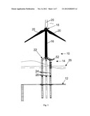
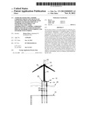
[0021] FIG. 1 depicts a side view of an offshore wind power plant with a cathodic corrosion protection device according to one embodiment of the invention;
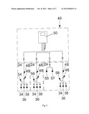
[0022] FIG. 2 depicts an installation schema of the cathodic corrosion protection device of the offshore wind power plant of FIG. 1;
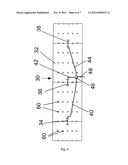
[0023] FIG. 3 depicts the inside of the winding of the cylinder ring of an anode retainer of the cathodic corrosion protection device of the offshore wind power plant of FIG. 1;
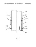
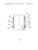
[0024] FIGS. 4 and 5 depicts steps for placing or pushing a cylinder ring on to a foundation pipe of the offshore wind power plant of FIG. 1 under the effect of gravity;
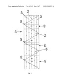
[0025] FIG. 6 depicts the outside of the winding of the cylinder ring of an anode retainer of the cathodic corrosion protection device of the offshore wind power plant of FIG. 1 with fixed anodes; and
[0026] FIG. 7 depicts a detailed view of the indicated inside of FIG. 6.
DETAILED DESCRIPTION
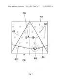
[0027] FIG. 1 depicts a side view of an offshore wind power plant 10 that is installed on the seabed 12. The offshore wind power plant 10 includes a foundation 14, a tower 16 and a hub 18 with rotor vanes 20. The foundation 14 is a "tri-pile", which comprises a supporting cross 22 and three foundation pipes 24. The foundation pipes 24 are rammed into the seabed 12. An anode retainer 28 is concentrically arranged below the water level 26 around each foundation pipe 24 on the same plane. The anode retainer 28 comprises a 3-metre-high cylinder ring made of steel. The outside 32 of the winding of the cylinder ring 30 is shown in FIG. 6. Three anodes 34, 36 and 38 are arranged equidistantly over the periphery of the cylinder ring 30 and horizontally arranged in the installation state. The anodes 34, 36 and 38 are connected via respective cables 40, 42 and 44 to a distributor box 46 which is in turn electrically connected via a respective cable 48 to a protective current unit 50 with an integrated control device (not shown) (see also FIG. 2).
[0028] As also follows by reference to FIG. 2, two types of reference electrodes are provided for controlling and monitoring a cathodic corrosion protection device 49 which includes inter alia the anode retainers 28 with respectively three anodes 34, 36 and 38 and the protective current unit 50. Two control electrodes 55 and 57 are provided in tubular containers (not shown) on a pier 52 (see FIG. 1) and monitoring electrodes 54, 56 and 58 are arranged in the vicinity of the respective distributor box 46 or, in some embodiments, therein.
[0029] As follows from FIGS. 3 and 6, the cylinder ring 30 comprises passage holes 60 in its outside 32 which have a diameter of 100 mm and are arranged at a distance a of 500 mm in the longitudinal direction and at a distance b of 909 mm in the peripheral direction.
[0030] As further follows from FIGS. 3 and 7, conically pointed guide plates 64 are welded on the inside 62 of the cylinder ring 30. At the narrow ends of the guide paths 66 resulting through the guide plates 64 a respective fit 68 is provided for a respective positioning projection (see FIGS. 4 and 5). The positioning projections 70 are arranged in two planes in the longitudinal direction of the foundation pipe 24 (see FIGS. 4 and 5). The positioning projections 70 in the upper plane after installation (also called the first plane) have two functions. The first function consists in the self-positioning of the cylinder ring 30 under the effect of gravity. The positioning takes place in that the diagonally extending guide plates 64 welded to the inside 62 of the cylinder ring 30 slide on said positioning projections 70 in the upper plane. The cylinder ring 30 is thereby set in rotation depending upon the initial arrangement and allowed to slide into the provided position under the effect of gravity.
[0031] The second function of the positioning projections 70 in the upper plane consists in the, fixing preferably force-locking, of the cylinder ring 30 against rotation in that the positioning projections 70 slide in the upper plane in the upper region of the cylinder ring into the fit 68. The lower plane (also called the second plane) of the positioning projections 70 serves as a support in vertical direction. For this purpose the positioning projections 70 comprise in the lower plane a stop surface 72 perpendicular to the longitudinal axis of the foundation pipe 24. As the positioning projections 70 are formed outwardly conically in the lower plane, a wedging of the cylinder ring 30 in horizontal direction takes place in the installation state.
[0032] The metallic cylinder ring 30 comprises on its outside 22 an essentially non-electrically-conductive coating. An example of one such suitable coating is Derakane 8090 epoxy vinyl ester resin.
[0033] The cathodic corrosion device 49 is a device for cathode protection with predefined current (Impressed Current Cathodic Protection--ICCP). By means of the various electrical parameters such as voltage, field strength, and power, the mode of functioning of the corrosion protection device can be monitored and correspondingly adjusted. The field strength can be measured through the reference electrodes.
[0034] The features of the invention disclosed in the present description, in the drawings and in the claims can be essential both individually and also in any combinations for the realization of the invention in its different embodiments.
User Contributions:
Comment about this patent or add new information about this topic:
Images included with this patent application:
 |  |
 |  |
 |  |
 |  |
| Similar patent applications: | |
| Date | Title |
|---|---|
| 2014-01-23 | Machine and method for forming an in ground granular column |
| 2014-01-16 | Offshore horizontal product lay arrangement |
| 2014-01-23 | Submersible apparatus and methods of installing anchoring equipment |
| 2010-05-27 | Automatic gated pipe actuator |
| 2013-12-19 | Removal of carbon dioxide from air |
| New patent applications in this class: | |
| Date | Title |
|---|---|
| 2015-10-15 | Working platform for an offshore wind energy plant and method for manufacturing the same |
| 2012-07-12 | Steel pipe piles and pipe pile structures |
| 2011-06-02 | Cathodic protection monitoring |
| 2008-08-21 | Retrievable surface installed cathodic protection for marine structures |
| Top Inventors for class "Hydraulic and earth engineering" | |
| Rank | Inventor's name |
|---|---|
| 1 | Joop Roodenburg |
| 2 | Thomas P. Taylor |
| 3 | Michael Tjader |
| 4 | Keith K. Millheim |
| 5 | John G. Oldsen |