Patent application title: HAIR DYEING TOOL
Inventors:
Denivaldo Gonçalves Da Silva (Sao Bernardo Do Campo, BR)
IPC8 Class: AA45D1902FI
USPC Class:
132270
Class name: Toilet hair device including means to isolate or part a tress of hair for chemical treatment (e.g., frosting cap or purse)
Publication date: 2012-11-01
Patent application number: 20120272995
Abstract:
A hair dyeing tool comprising a tray (3) with a curved bottom wall (12)
contiguous with the side walls (13) of said tray; the surface of the
bottom wall (12) is designed to cause the bristles in groups of bristle
tufts (5) and (7) to be oriented against each other when the brush (4) is
pushed against the tray (3); the orientation of the bristles in the
groups of bristle tufts (5) and (7) creates a tunnel-like space (E)
through which the hair strands (C) are pushed during dyeing. The
curvature of the surface of the bottom wall (12) is designed to connect
in an arc the center line.Claims:
1. "HAIR DYEING TOOL", which is indicated by reference number 1, and
comprises a flexible structure resembling tweezers (2), with a part that
is similar to a small tray (3) on one of its ends, and on its other end a
part that is similar to a brush (4) with groups of bristle tufts (5),
(6), and (7) on its lower face; the groups of bristle tufts (5), (6), and
(7) are developed such that the group of bristle tufts (5) has bristles
of a given length which is longer than the length of two other groups of
bristle tufts (6) and (7), whereas said group of bristle tufts (6), in
turn, has shorter bristle length compared to the group of bristle tuft
(7); the tray (3) has a raised, angled lateral end (8) and an opposing
end (9) which follows the general surface level of the tray (3); the
lateral end (8) of the tray (2) [sic] has a U-shaped opening (10),
whereas another U-shaped opening (11) is provided on the opposite end
(9); the tool 1 is characterized in that the bottom wall (12) of the tray
(3) is curved and is continuous with its lateral walls (13); the surface
of the bottom wall (12) of the tray (3) is implemented so as to serve as
the center point for the bristles included in the groups of bristle tufts
(5) and (7) to go in opposite directions against one another when the
brush (4) is pressed against the tray (3); the orientation given to the
bristles of the groups of bristle tufts (5) and (7) creates a space (E)
that is similar to a tunnel through which the hair strands (C) are forced
during the dyeing process; the curvature of the surface of the bottom
wall (12) is defined so as to link the center line of said wall (12)
referenced as (12a) to the ends of the side walls (13), thus creating a
sliding surface for the bristles of the two groups of bristle tufts (5)
and (7); the tray (3) may provide a variant wherein the structure
provided in the angled, raised lateral end (8) is also provided on its
opposite end (9).Description:
[0001] The present description relates to a Utility Model that proposes an
innovation in a tool for dyeing hair that may be used both in
professional and home settings.
[0002] Known in the prior art are a wide variety of hair dyeing tools, among which there is a specific model that, in general terms, includes a flexible structure similar to tweezers with a small tray-like part on one of its ends and a brush-like part with groups of bristle tufts on the other end.
[0003] This type of tool is used for applying highlights to hair; its use provides, initially, application of a dye substance or the like directly onto the brush bristles. After that, the tweezer-like structure is pressed at the same time that a small volume of hair is placed on the tray-like part.
[0004] After the tool is closed, it is passed along the group of hair strands selected with the result that they come into contact with the dye-impregnated bristles and are then suitably dyed.
[0005] Despite the fact that this type of tool is quite easy to use, it has a basic aspect that is open to innovation with respect to the configuration of the tray-like part, with its substantially flat bottom and curved, short side walls that are basically vertical, thus forming a corner in the area of intersection between the bottom surface and the walls.
[0006] This type of configuration given to the tray-like part makes proper positioning of the brush bristles difficult when it is time for the dye to be applied to the hair, given that said bristles tend to spread in a rather disorderly fashion when they are pressed against the flat surface at the bottom of the tray.
[0007] Therefore, one of the objects of this Utility Model is to provide a hair dyeing tool that is similar to the prior art in its general structure, with devices shaped like tweezers, a tray, and a brush. The innovative tool differs from the conventional model in that its tray-like part has, in contrast to the model currently in use, a bottom surface essentially rounded in the longitudinal direction of the part, thus creating a continuous, curved surface that also includes the side walls of said part.
[0008] The innovation introduced in said tray-like part allows the brush bristles to be positioned so as to converge toward the middle of the brush when pressed against it. This allows the bristles to form a tunnel-like space along the brush, through which the hair to be dyed must pass.
[0009] The space between the bristles provides full coverage of the hair, thus improving the conditions of dye application on the hair and resulting, consequently, in better dye application.
[0010] The hair dyeing tool constituting an object of this Utility Model also proposes a variant with two end walls that act so as to better guide the volume of hair strands through a tray-shaped passage.
[0011] The tool in question shall be described in detail with reference to the drawings below wherein:
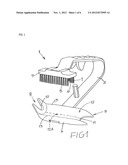
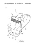
[0012] FIG. 1 depicts a perspective view of the proposed tool, in its neutral state;
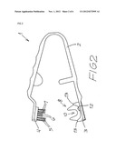
[0013] FIG. 2 depicts a side view of said tool, in its neutral state;
[0014] FIG. 3 depicts a schematic view indicating the position of a given volume of hair (in cross-section) over the tray-like part;
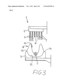
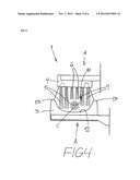
[0015] FIG. 4 depicts a first step of closing the tool, wherein its brush is pressed against the tray-like part, as is schematically indicated by the arrows "A";
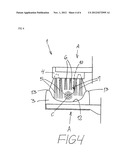
[0016] FIG. 5 depicts the step following that of FIG. 4, wherein, due to the continuing closing of the tool as indicated by the arrows "A", the brush bristles come into contact with the curved surface of the tray-shaped piece and are then deflected as indicated by the arrows "B", so as to converge, thus forming the tunnel-like space that completely surrounds the volume of hair to be dyed; and
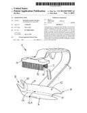
[0017] FIG. 6 depicts a variant of the tool in question.
[0018] According to the figures listed above, the hair dyeing tool in question is referenced, generally, by the number 1 and comprises a flexible structure that is similar to tweezers 2, which has a piece that is similar to a small tray 3 at the end of one of its arms, and a piece similar to a brush 4 at the end of its other arm, including on its lower face groups of bristle tufts 5, 6, and 7 of different lengths.
[0019] The tool 1 is constructed to be handled such that when the tweezer-like structure 2 is squeezed, the tray 3 and the brush 4 come together, as depicted schematically in FIGS. 4 and 5.
[0020] The groups of bristle tufts 5, 6, and 7 are developed such that the group of bristle tufts 5 has bristles of a given length, which is longer than the length of the two other groups of bristle tufts, i.e., the groups of bristle tufts 6 and 7, whereas, in turn, said group of bristle tufts 6 has shorter bristle length compared to the group of bristle tufts 7.
[0021] The tray 3 has a raised, angled lateral end 8 and an opposing end 9 which follows the general surface level of the tray 3, as depicted in FIGS. 1, 2, 3, 4, and 5.
[0022] The lateral end 8 of the tray 3 has a U-shaped opening 10, whereas another U-shaped opening 11 (with a wider mouth) is provided on the opposite end 9.
[0023] The tool 1 in question, in contrast to what is seen in similar tools belonging to the prior art, has, with regard to its tray-like part 3, a special configuration on the surface of its bottom wall 12, which is curved and continuous with the lateral walls 13.
[0024] The surface of the bottom wall 12 which is part of the tray 3 is implemented so as to serve as the center point for the bristles included in the groups of the bristle tufts 5 and 7 to go in opposite directions against one another when the brush 4 is pressed against the tray 3 as is depicted in FIG. 5 and according to what is indicated by the arrows "B" in said figure.
[0025] The orientation given to the bristles of the groups of bristle tufts 5 and 7 creates a space E that is similar to a tunnel through which hair strands C are forced to pass during the dyeing process.
[0026] The space E, thus defined, envelops the entire volume of hair strands C that is being dyed, thus improving the conditions of dye transfer previously applied to the bristles of the brush 4 and going from them to the hair strands C.
[0027] The creation of the space E is only possible due to the curve incorporated into the surface of the bottom wall 12 of the tray-shaped part 3, when the brush 4 is pushed against it, causing the end of the bristles of the groups of bristle tufts 5 and 7 to move such that they come together.
[0028] The curvature of the surface of the bottom wall 12 is defined so as to link the center line of said wall (indicated in the drawing as a dashed line present only in FIGS. 1 and 6, and referenced as 12a) in a constant curved line, to the ends of walls 13, thus creating a sliding surface for the bristles of the two groups of bristle tufts 5 and 7.
[0029] The present utility model also includes, as depicted in FIG. 6, a variant of the model of the tool 1 depicted in FIGS. 1 through 5, wherein the structure provided in an angled, raised lateral end 8 of the tray 3 is also provided on the opposite end of said part, thereby creating a configuration that promotes greater dye retention in the space circumscribed by the tray 3.
User Contributions:
Comment about this patent or add new information about this topic:
| People who visited this patent also read: | |
| Patent application number | Title |
|---|---|
| 20210385693 | METHOD AND APPARATUS FOR CONTROLLING QUALITY OF SERVICE OF SIDELINK COMMUNICATION, MEDIUM, AND ELECTRONIC DEVICE |
| 20210385692 | APPARATUS AND METHODS FOR POWER SAVE IN MULTI-LINK WIRELESS SYSTEMS |
| 20210385691 | Notifying a Management System of Quality of Experience Measurement Reporting Status |
| 20210385690 | METHOD AND SYSTEM FOR SMART OPERATING BANDWIDTH ADAPTATION DURING POWER OUTAGES |
| 20210385689 | METHOD AND SYSTEM FOR SMART OPERATING BANDWIDTH ADAPTATION DURING POWER OUTAGES |
Images included with this patent application:
 |  |
 |  |
 |  |
 |
| Similar patent applications: | |
| Date | Title |
|---|---|
| 2010-05-27 | Hair dyeing or bleaching method |
| 2010-09-23 | Head hair dyeing method |
| 2011-09-08 | Head hair dyeing method |
| 2011-09-29 | Hair styling tool |
| 2012-01-19 | Hair dyeing composition |
| New patent applications in this class: | |
| Date | Title |
|---|---|
| 2014-12-18 | Head cover having selectable size and location of opening for exposure of a portion of a user's hair |
| 2014-05-08 | Hair color foil holder |
| 2014-03-20 | Tool for separating a hair bundle |
| 2014-02-20 | Cosmetic color applicator and method for using same |
| 2014-01-23 | Hair styling tool |
| New patent applications from these inventors: | |
| Date | Title |
|---|---|
| 2012-03-08 | Method for producing a hair shine cosmetic, and hair shine cosmetic product |
| Top Inventors for class "Toilet" | |
| Rank | Inventor's name |
|---|---|
| 1 | Nghi Van Nguyen |
| 2 | Jonathan Wood |
| 3 | Siliu Tan |
| 4 | Sawa Hashimoto |
| 5 | Henri Samain |