Patent application title: Divot Tool
Inventors:
Leland Craig Sharp (Middletown, CA, US)
IPC8 Class: AA63B5700FI
USPC Class:
473408
Class name: Games using tangible projectile golf player manipulated turf repair tool
Publication date: 2011-12-08
Patent application number: 20110300973
Abstract:
A divot tool to repair damage to a golf green may include a body portion,
and the body portion may include a first tine and a second tine which
extends outwards from the body portion. The body portion may be
circumferentially shaped. The divot tool may include a connection section
to connect to a handle. The connection section may include a cylinder
portion. The connection section may include a inclined portion.Claims:
1) A divot tool to repair damage to a golf green, comprising: a body
portion; the body portion including a first tine and a second tine which
extends outwards from the body portion.
2) A divot tool to repair damage to a golf green as in claim 1, wherein the body portion is circumferentially shaped.
3) A divot tool to repair damage to the golf green as in claim 1, wherein the divot tool further includes a connection section to connect to a handle.
4) A divot tool to repair damage to the golf frame as in claim 3, wherein the connection section includes a cylinder portion.
5) A divot tool to repair damage to the golf green as in claim 4, wherein the connection section includes a inclined portion.
Description:
FIELD OF THE INVENTION
[0001] The present invention relates to golf tools and more particularly to a divot tool.
BACKGROUND
[0002] Maintaining the condition of a golf course is of prime concern, especially with the increased amount of play due to the growing popularity of the sport. One of the most important areas of the golf course is the putting green which must be maintained in near perfect condition so that the golf ball rolls true along the putting surface. Unfortunately the putting green is often damaged by foot traffic across the green and ball impact damage. Damaged areas of the golf course playing surface caused by such use are commonly called divots or ball marks. In order to maintain the condition of the course, players are urged to repair all divots that they notice or create during a round of play. Particular attention is urged with regard to the putting surface of the greens due to the sensitive nature of their effect upon a player's score. An immediate repair facilitates the natural recovery of the grass system which would otherwise dry out, preventing the grass root system from re-growing. In order to facilitate the repair of putting green divots, various tools have been devised for golfers to carry and use. Divot repair tools are typically fork-shaped implements having tines that are pressed into the playing surface which can then be lifted or otherwise manipulated to restore its condition. Some divot repair tools are incorporated into the end of the handle or grip end of the golf putter. Examples are shown in various prior art patents such as U.S. Pat. No. 4,862,970 issued to Hlavacek; U.S. Pat. No. 5,511,785 issued to Rusin, Jr.; U.S. Pat. No. 5,377,977 issued to MacNeary; and U.S. Pat. No. 6,502,646 issued to Wiens. Each of these patents discloses a divot repair tool which is extendable from and retractable back into the golf putter shaft, each having a different mechanical mechanism for controlling the movement and positioning of the divot repair tool. However, in each of these cases, there are limitations. For example, in some cases the golf putter shaft needs to be greatly modified. In other cases, the repair tool is not easily actuated or held in its locked operative position. For example, in the case of U.S. Pat. No. 4,862,970 issued to Hlavacek, the divot repair tool always remains protruding from the top of the handle and the tines must be manually pulled out of the top by tinenail grooves. This is particularly inconvenient in that grasping the tines is difficult and by the nature of their use the tines are most often covered with dirt. This makes use of this particular device inconvenient and unsanitary.
[0003] There is therefore a need in the art for an improved divot repair tool which is easy to use, is safe and sanitary and which is economical to manufacture.
Summary
[0004] A divot tool to repair damage to a golf green may include a body portion, and the body portion may include a first tine and a second tine which extends outwards from the body portion.
[0005] The body portion may be circumferentially shaped.
[0006] The divot tool may include a connection section to connect to a handle.
[0007] The connection section may include a cylinder portion.
[0008] The connection section may include a inclined portion.
BRIEF DESCRIPTION OF THE DRAWINGS
[0009] The invention may be understood by reference to the following description taken in conjunction with the accompanying drawings, in which, like reference numerals identify like elements, and in which:
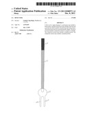
[0010] FIG. 1 illustrates present invention attached to a shaft and grip;
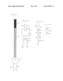
[0011] FIG. 2 illustrates a front/back view of the divot tool of the present invention;
[0012] FIG. 3 illustrates a side view of the divot tool of the present invention;
[0013] FIG. 4 illustrates a top view of the divot tool of the present invention.
DETAILED DESCRIPTION
[0014] FIG. 1 illustrates another embodiment and illustrates the divot tool 600 which may include a handle section 631 which may be connected to a shaft section 633 which may be connected to a divot tool head section 635 which may include a first tine member 637 and a second tine member 639.
[0015] FIGS. 2-4 illustrate an embodiment of the present invention.
[0016] FIG. 2 illustrates a front view (and rear view) of the divot tool 800 of the present invention. The divot tool 800 may include a connection section 801 for connection to a handle (not shown), a body portion 803, a first tool tine 805 and a second tool tine 807. The body portion 803 may be circumferentially shaped such as a circle or ellipse or other curve. The body portion 803 may include a top surface 809, an opposing bottom surface 811 and a peripheral edge 813 which extend between the top surface 809 and the opposing bottom surface 811. The first tool tine 805 and the second tool tine 807 may extend outwards from the body portion 803 in a parallel fashion or nonparallel fashion. The first tool tine 805 and the second tool tine 807 may have a sharpened edge or may not have a sharpened edge and may terminate in a point or may terminate in substantially a rounded end. The first tool tine 805 and the second tool tine 807 may include a top surface 819, an opposing bottom surface 815 and a side surface 817 to connect the top surface 819 and the bottom surface 815. The divot tool 800 which may include the first tool tine 805 and a second tool tine 807 may be formed from a flat sheet or plate of metal, plastic or other suitable ridged material. The connection section 801 may include an inclined portion 831 and a cylinder portion 833 for connection to a handle and may include an aperture 835 to accept a handle (not shown). The connection section 801 may include a cut to cooperate with the body portion 803.
[0017] FIG. 3 illustrates a side view of the divot tool 800 of the present invention. The divot tool 800 may include a connection section 801 for connection to a handle (not shown), a body portion 803, a first tool tine 805 and a second tool tine 807. The body portion 803 may be circumferentially shaped such as a circle or ellipse or other curve. The body portion 803 may include a top surface 809, an opposing bottom surface 811 and a peripheral edge 813 which extend between the top surface 809 and the opposing bottom surface 811. The first tool tine 805 and the second tool tine 807 may extend outwards from the body portion 803 in a parallel fashion or nonparallel fashion. The first tool tine 805 and the second tool tine 807 may have a sharpened edge or may not have a sharpened edge and may terminate in a point or may terminate in substantially a rounded end. The first tool tine 805 and the second tool tine 807 may include a top surface 819, an opposing bottom surface 815 and a side surface 817 to connect the top surface 819 and the bottom surface 815. The divot tool 800 which may include the first tool tine 805 and a second tool tine 807 may be formed from a flat sheet or plate of metal, plastic or other suitable ridged material. The connection section 801 may include an inclined portion 831 and a cylinder portion 833 for connection to a handle and may include an aperture 835 to accept a handle (not shown). The connection section 801 may include a cut to cooperate with the body portion 803.
[0018] FIG. 4 illustrates a top view of the divot tool 800 and illustrates the top surface of the connection section 833 and illustrates the body section 803.
[0019] While the invention is susceptible to various modifications and alternative forms, specific embodiments thereof have been shown by way of example in the drawings and are herein described in detail. It should be understood, however, that the description herein of specific embodiments is not intended to limit the invention to the particular forms disclosed.
User Contributions:
Comment about this patent or add new information about this topic:
| People who visited this patent also read: | |
| Patent application number | Title |
|---|---|
| 20220245490 | SYSTEM AND METHOD FOR HETEROGENEOUS MULTI-TASK LEARNING WITH EXPERT DIVERSITY |
| 20220245489 | AUTOMATIC INTENT GENERATION WITHIN A VIRTUAL AGENT PLATFORM |
| 20220245488 | ACCURATE AND PERSONALIZED RECOMMENDATION METHOD BASED ON KNOWLEDGE GRAPH |
| 20220245487 | FEATURE PREDICTION METHOD, SYSTEM AND ENGINE |
| 20220245486 | PREDICTION DEVICE, PREDICTION METHOD, AND PREDICTION PROGRAM |
Images included with this patent application:
 |  |
| New patent applications in this class: | |
| Date | Title |
|---|---|
| 2016-07-07 | Divot repair tool |
| 2016-07-07 | Turf repair apparatus |
| 2016-06-16 | Divot repair apparatus |
| 2016-05-05 | Divot repair tool |
| 2016-05-05 | Divot repair tool |
| Top Inventors for class "Games using tangible projectile" | |
| Rank | Inventor's name |
|---|---|
| 1 | Michael J. Sullivan |
| 2 | Brian Comeau |
| 3 | Derek A. Ladd |
| 4 | David A. Bulpett |
| 5 | Mark L. Binette |