Patent application title: Integrated Air/Oil Reservoir Cooler and Noise Reduction System
Inventors:
Dwight Booth (Milton, WI, US)
IPC8 Class: AF28D1500FI
USPC Class:
16510434
Class name: Heat exchange intermediate fluent heat exchange material receiving and discharging heat including means to move gaseous heat exchange material
Publication date: 2011-06-23
Patent application number: 20110146958
Abstract:
A cooling system and method are provided to cool a working fluid in an
inner tank. The cooling system includes an outer tank and a gap formed
between the inner tank and outer tank. The cooling system further
includes a baffle disposed in the gap to damp a flow of a cooling liquid
that is introduced into the gap. The baffle is designed to decrease the
noise and turbulence that can occur with the introduction of the cooling
liquid into the gap.Claims:
1. A cooling system for a pump, comprising: an inner tank that holds a
hydraulic fluid that is used by the pump; an outer tank that surrounds
the inner tank; a gap formed between an outer surface of the inner tank
and an inner surface of the outer tank; and a baffle disposed in the gap,
wherein the baffle redirects a flow of a cooling fluid that results in
reduction of the flow of the cooling fluid that is introduced into the
gap and can maintain an integrated relationship with a cooling
capability.
2. The cooling system of claim 1, wherein the baffle reduces noise and any turbulence created by the flow of the cooling fluid in the gap.
3. The cooling system of claim 1, wherein the baffle includes a first component and a second component that are angled in relation to each other.
4. The cooling system of claim 1, wherein the outer tank further comprises a fluid opening that is used to introduce the cooing fluid into the gap.
5. The cooling system of claim 1, wherein the cooling fluid is compressed air.
6. The cooling system of claim 1, wherein the baffle is located after an entry point into the gap for the cooling fluid.
7. The cooling system of claim 1, wherein the outer tank further includes an upper surface that forms a seal with a portion of the inner tank.
8. The cooling system of claim 1, wherein a maximum temperature drop in the cooling system occurs at the fluid opening designed to receive cooling fluid into the gap.
9. A cooling system for a pump, comprising: a first means for containing that holds an operating fluid that is used by the pump; a second means for containing that surrounds the first means for containing; a gap formed between an outer surface of the first means for containing and an inner surface of the second means for containing; and a means for damping disposed in the gap, wherein the means for damping reduces a flow of a cooling fluid that is introduced into the gap.
10. The cooling system of claim 9, wherein the means for damping reduces noise and any turbulence created by the flow of the cooling fluid in the gap.
11. The cooling system of claim 9, wherein the means for damping includes a first component and a second component that are angled in relation to each other.
12. The cooling system of claim 9, wherein the second means for containing further comprises a fluid opening that is used to introduce the cooing fluid into the gap.
13. The cooling system of claim 9, wherein the cooling fluid is compressed air.
14. The cooling system of claim 9, wherein the means for damping is located after an entry point into the gap for the cooling fluid.
15. The cooling system of claim 9, wherein the second means for containing further includes an upper surface that forms a seal with a portion of the first means for containing.
16. The cooling system of claim 9, wherein a maximum temperature drop in the cooling system occurs at fluid opening designed to receive cooling fluid into the gap.
17. A method of cooling a liquid in an inner tank, comprising the steps of: containing a working fluid in the inner tank; introducing a cooling fluid into a gap created by the inner tank and an outer tank; cooling the working fluid in the inner tank with the cooling fluid by flowing the cooling fluid pass the inner tank and a baffle coupled to the inner tank; and damping a noise with the baffle.
18. The method of cooling of claim 17 further comprising existing the cooling fluid from a side of the outer tank.
19. The method of claim 17, wherein the cooling fluid is compressed air.
20. The method of claim 17, further comprising damping a vibration with the baffle.
Description:
FIELD OF THE INVENTION
[0001] The present invention relates generally to a reservoir cooler. More particularly, the present invention relates to an integrated air/oil reservoir cooler and noise reduction system.
BACKGROUND OF THE INVENTION
[0002] Air/hydraulic pumps are used when air is the preferred power source or where electricity is not readily available. Further, these pumps are ideally used in petrochemical and mine applications and flammable and explosive environments. The pumps that are high performance provide consistently high hydraulic flow and pressure for faster tool operation.
[0003] During use, the hydraulic fluid in the reservoir can heat up and must be cooled down in order for the pump to effectively operate. However, conventional cooling systems are not performing as required and the pumps are running too hot. Further, the motor of the pumps often include muffler systems to reduce noise that often ice up during operation due to freezing caused by moisture in the ambient air.
[0004] Accordingly, it is desirable to provide a pump that includes a cooling system that performs as needed and include a noise reduction system and is resistant to freezing up.
SUMMARY OF THE INVENTION
[0005] The foregoing needs are met, to a great extent, by the present invention, wherein in one aspect an apparatus is provided that in some embodiments include a cooling system. An inner tank holds a working fluid and a gap is created between the inner tank and an outer tank. A baffle is disposed within the gap to damp the noise and any vibration caused by the introduction of a cooling fluid into the gap. The cooling fluid will cool the working fluid in the inner tank and the heat dissipated by the baffle, and the outer shell.
[0006] In accordance with one embodiment of the present invention, a cooling system for a pump is provided, which can include an inner tank that holds a hydraulic fluid that is used by the pump, an outer tank that surrounds the inner tank, a gap formed between an outer surface of the inner tank and an inner surface of the outer tank, and a baffle disposed in the gap, wherein the baffle redirects a flow of a cooling fluid which results in reduced flow that is introduced into the gap and can maintain an integrated relationship with the cooling capability.
[0007] In accordance with another embodiment of the present invention, a cooling system for a pump is provided, which can include a first means for containing that holds an operating fluid that is used by the pump, a second means for containing that surrounds the first means for containing, a gap formed between an outer surface of the first means for containing and an inner surface of the second means for containing, and a means for damping disposed in the gap, wherein the means for damping reduces a flow of a cooling fluid that is introduced into the gap.
[0008] In accordance with yet another embodiment of the present invention, a method of cooling a liquid in an inner tank is provided, which can include containing working fluid in the inner tank, introducing a cooling fluid into a gap created by the inner tank and an outer tank, cooling the working fluid in the inner tank with the cooling fluid by flowing the cooling fluid past the inner tank and a baffle coupled to the inner tank, and damps a noise with the baffle.
[0009] There has thus been outlined, rather broadly, certain embodiments of the invention in order that the detailed description thereof herein may be better understood, and in order that the present contribution to the art may be better appreciated. There are, of course, additional embodiments of the invention that will be described below and which will form the subject matter of the claims appended hereto.
[0010] In this respect, before explaining at least one embodiment of the invention in detail, it is to be understood that the invention is not limited in its application to the details of construction and to the arrangements of the components set forth in the following description or illustrated in the drawings. The invention is capable of embodiments in addition to those described and of being practiced and carried out in various ways. Also, it is to be understood that the phraseology and terminology employed herein, as well as the abstract, are for the purpose of description and should not be regarded as limiting.
[0011] As such, those skilled in the art will appreciate that the conception upon which this disclosure is based may readily be utilized as a basis for the designing of other structures, methods and systems for carrying out the several purposes of the present invention. It is important, therefore, that the claims be regarded as including such equivalent constructions insofar as they do not depart from the spirit and scope of the present invention.
BRIEF DESCRIPTION OF THE DRAWINGS
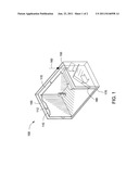
[0012] FIG. 1 illustrates a cross sectional view of a hydraulic reservoir of a pump having a cooling system according to an embodiment of the invention.
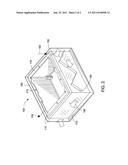
[0013] FIG. 2 illustrates the inner tank with the cooling system according to an embodiment of the invention.
DETAILED DESCRIPTION
[0014] The invention will now be described with reference to the drawing figures, in which like reference numerals refer to like parts throughout. An embodiment in accordance with the invention provides a pump, such as an air/hydraulic pump that includes a cooling system that cools a working fluid such as hydraulic fluids used in the pump and reduces noise during the cooling system's operation.
[0015] The working fluid can be any fluid including, for example, hydraulic fluids, oils, lubricants, water, phosphate ester, water-based ethylene glycol compounds, and silicone fluids. Three most common types of hydraulic liquids are petroleum-based, synthetic fire-resistant, and water-based fire-resistant. The working fluid can be synthetic, naturally occurring or a combination thereof. As noted, any working fluid can be used with the invention and hydraulic fluid is just one exemplary fluid that can be used with invention. The cooling system combines a noise and vibration abatement system while reducing the heat in the working fluid reservoir.
[0016] FIG. 1 illustrates a cross sectional view of a hydraulic fluid reservoir 100 of a pump having a cooling system according to an embodiment of the invention. The hydraulic fluid reservoir 100 includes an inner tank 110, an outer tank 150 and a gap 170 defined by the inner and outer tanks 110, 150. The inner tank 110 contains the hydraulic fluid that needs to be cooled so that the pump can remain operational for a longer period of time.
[0017] The inner tank 110 can be made of any material including heat conducting material so that the inner tank can be cooled by a cooling fluid in the gap 170. For example, the inner tank 110 can be made from steel, metal, copper, aluminum, tin and other similar materials that conduct heat. Further the inner tank 110 can be any shape including square, rectangular, triangular and similar shapes so long as it can contain the hydraulic fluid.
[0018] The inner tank 110 can include on an upper surface 115 that can be coupled to the pump itself. In one embodiment, the inner tank 110 is bolted to the pump via holes 112. The holes 112 can receive various bolting components such as a bolt, screws, nuts and similar components. Further, the inner tank 110 can be welded, glued or otherwise coupled to the pump. The inner tank 110 and the outer tank 150 can be constructed so that they can simply replace the existing fluid reservoir of a pump so that the user does not have to buy a new pump to take advantage of the invention described herein.
[0019] The outer tank 150 surrounds the inner tank 110. In one embodiment, the outer tank 150 surrounds all sides of the inner tank. For example, if the pump is attached to a side of the inner tank 110 then the outer tank 150 can surrounds the remaining sides. In other embodiments, the outer tank 150 partially surrounds the inner tank 110, such as one side, two sides, three sides, four sides, and five sides, etc. The sides covered by the outer tank in relation to the inner tank will depend on the amount of cooling that is needed and is based on the heat transfer rate and surface area needed.
[0020] The outer tank 150 can be made of any material including heat conducting material or heat insulating material or a combination thereof. For example, the outer tank 150 can be made from steel, metal, copper, aluminum, tin and other similar materials that conduct heat. In another example, the outer tank can be made from fiber glass, polyurethane foam and similar heat insulating materials. Further, the inner tank 110 can be any shape including square, rectangular, triangular and similar shapes. The outer tank 150 can also be shaped the same shape or different shape as the inner tank 110. Additionally, the inner and outer tanks 110, 150 can be durable or flexible so long as it can contain the hydraulic fluid.
[0021] The outer tank 150 includes an upper surface 155 that contacts the inner tank. The upper surface 155 of the outer tank 150 can be at the same height as the upper surface 115 of the inner tank 110. Alternatively, the upper surface 155 of the outer tank 150 can be lower or higher than the upper surface 115 of the inner tank 110. In one embodiment, the upper surface 155 of the outer tank 150 can form a seal with the inner tank 110. By forming a seal, the cooling fluid can be better contained within the gap 170.
[0022] The upper surface 155 of the outer tank 150 includes a fluid opening 160 so that a fluid such as a cooling fluid can be introduced into the gap 170. There can be more than one fluid opening 160 or as many that are needed by the particular application. The more fluid opening, the faster the hydraulic fluid can be cooled. The cooling fluid can include a refrigerant, air, including compressed air and air motor exhaust, glycols, water and other cooling fluids. The cooling fluid will flow in the gap to cool the inner tank or can simply sit in the gap 170. The cooling fluid can flow into the gap 170 until it exits out of the gap (not shown).
[0023] If air is used, then cold compressed air can be used and where it enters (at the fluid opening 160) is where there is a maximum temperature drop. When compressed air is used, turbulence can be created when it is being introduced into the gap and disruptive noise and vibrations are created. Thus, the noise and vibration need to be abated (discussed below).
[0024] The gap formed between the outer tank and the inner tank causes a pressure drop in the area where cooling is needed. The drop in pressure creates a drop in the temperature in the gap, thereby causing the hydraulic fluid in the inner tank to cool down.
[0025] A baffle 180 is placed or formed in the gap 170. The baffle 180 is constructed and designed to perform at least two functions. One function is to radiate heat or conduct heat into the gap 170 where it can be cooled by the cooling medium. The baffle 180 provides additional surface area for the inner tank to conduct heat away from itself and for the cooling medium to come into contact with the heat. As shown in FIGS. 1 and 2, in one embodiment, the baffle 180 includes two components that are angled at about 90 degrees to each other. However, other angles, such as 45, 60, 120 degrees and others would also work according to embodiments of the invention. In another embodiment, the baffle 180 can be formed in one piece or integral with the inner tank or the outer tank.
[0026] The second function of the baffle 180 is to damp or abate the noise that the cooling fluid can cause. By angling the baffle 180, the flow of the cooling fluid in the gap 170 is decreased, which leads to less noise and vibration in the cooling system. The baffle can redirect the flow for the entire cooling fluid or for parts of the flow of the cooling fluid which results in reduced flow. For example, in any space between the baffle 180 and the outer tank 150 can flow fully. By decreasing the flow of the cooling fluid, less noise and vibrations are caused in the cooling system.
[0027] In one embodiment, the baffle 180 can be placed between the inner and outer tanks 110, 150. The baffle 180 can be held in place through friction fitting between the inner and outer tanks 110, 150 and can be placed anywhere in the gap 170. In another embodiment, the baffle 180 can be welded, glued or otherwise coupled to the inner tank 110 or outer tank 150. In still another embodiment, the baffle 180 can be formed as part of the inner or outer tanks. The baffle 180 can be made of the same or different materials as the inner tank 110 or the outer tank 150. The baffle 180 can be placed on one side of the inner tank 110 near the fluid opening or on as many sides of the inner tank as needed. In another embodiment, there can be more than one baffle on a particular side. The baffle can be coupled together or spaced apart from each other on a given side. In one example, there can be a baffle for each fluid opening in the system to slow the fluid at the point of entry into the gap 170 or there can be different ratios (fluid opening to baffle) such as 0.5, 1.5, 2.0, etc. The baffle can be placed at a point after where the cooling fluid is introduced.
[0028] FIG. 2 illustrates the inner tank 110 with the cooling system 100 according to an embodiment of the invention. The inner tank 110 can be filled with a working fluid such as a hydraulic fluid that is used by the pump. The hydraulic fluid will heat up during the pump's use and will need to cooled in order for the pump to be continuously used. In this view, the outer tank 150 surrounds five sides of the inner tank 110. Further, the upper portion 155 of the outer tank 150 is less in height than the upper portion 115 of the inner tank 110. However, the upper portion 155 forms a seal with the inner tank so that the cooling fluid is contained within the gap 170 formed by the inner and outer tanks 110, 150.
[0029] Baffle 180 is positioned on one side of the inner tank 110 to affect the flow of the cooling medium. In this embodiment, the cooling medium can be cold compressed air that is provided by a compressor (not shown). Most particularly, the cooling medium is cold compressed exhaust air that is provided by the air motor driving the pump. The compressed air can enter the gap 170 at the fluid opening 160 and travel in the direction shown by arrows 190. When the compressed exhaust air enters gap 180, the rapid change in volume causes the compressed air to release the energy and become cold. When the compressed air hits the baffle 180, it can travel in two directions. One direction is along the surface of the baffle where the flow is slowed due to the angle of the baffle. The second direction is in the openings between baffles and outer tank or even the inner tank (in some embodiments). The second direction may or may not slow down the flow of the cooling fluid.
[0030] The arrows 190 in the figures illustrate an example flow of the cooling fluid. As shown, the cooling fluid flows in the gap and cools the hydraulic fluid in the inner tank. The cooling fluid can exit at a side of the outer tank as shown by arrow 195. The cooling fluid can exit anywhere along a side of the outer tank as desired by the user. Further, the cooling fluid does not need to flow continuously to cool the inner tank and can remain stationary in the gap for a predetermined period of time.
[0031] In operation, cooling fluid can be introduced into the gap at the fluid opening. The fluid will flow around and/or along the baffles and also flow along the sides of the inner tank. The hydraulic fluid in the inner tank can be cooled as the cooling fluid is flowing. With the increase in surface area that the baffles provide, the hydraulic fluid is cooled even faster.
[0032] The baffles redirect the cooling fluid and as a result also slow down the cooling fluid so that noise and vibrations are decreased during the operation of the cooling system. The cooling fluid then can exit out of the outer tank at a predetermined location.
[0033] With the embodiments of the invention, the user will be less fatigued from the reduced noise and vibrations. Further, the user can operate the pump for a longer period of time since the hydraulic fluid is cooled down more efficiently by the invention. Further, the cooling of the hydraulic fluid provided for a safer pump due to reduced heat at the user's contact points. Further, the embodiments disclosed herein can be integrated into existing pump designs, thereby saving the user from buying a different pump.
[0034] The many features and advantages of the invention are apparent from the detailed specification, and thus, it is intended by the appended claims to cover all such features and advantages of the invention which fall within the true spirit and scope of the invention. Further, since numerous modifications and variations will readily occur to those skilled in the art, it is not desired to limit the invention to the exact construction and operation illustrated and described, and accordingly, all suitable modifications and equivalents may be resorted to, falling within the scope of the invention.
User Contributions:
Comment about this patent or add new information about this topic:
Images included with this patent application:
 |  |
| New patent applications in this class: | |
| Date | Title |
|---|---|
| 2016-05-05 | Heat exchanger |
| 2016-03-31 | Single actuator-operated cooling jet apparatus |
| 2016-03-17 | Fluid cooling pad system utilizes compressed air as a cooling source |
| 2016-02-04 | Gas storage modules, apparatus, systems and methods utilizing adsorbent materials |
| 2016-01-28 | Aircraft gaseous cooling system |
| New patent applications from these inventors: | |
| Date | Title |
|---|---|
| 2015-12-03 | Multi-part, manifold and method of making the manifold |
| 2014-12-25 | Pressure balanced hydraulic device and method |
| 2012-05-03 | Internally supplied air jet cooling for a hydraulic pump |
| 2012-05-03 | Internally directed air jet cooling for a hydraulic pump |
| Top Inventors for class "Heat exchange" | |
| Rank | Inventor's name |
|---|---|
| 1 | Levi A. Campbell |
| 2 | Chun-Chi Chen |
| 3 | Tai-Her Yang |
| 4 | Robert E. Simons |
| 5 | Richard C. Chu |