Patent application title: Security Load Bra
Inventors:
Richard Lynn Mcwain (Brazoria, TX, US)
IPC8 Class: AB65D6300FI
USPC Class:
410 96
Class name: Freight accommodation on freight carrier load lashing retainer or load lashing adjunct
Publication date: 2010-05-20
Patent application number: 20100124470
Inventors list |
Agents list |
Assignees list |
List by place |
Classification tree browser |
Top 100 Inventors |
Top 100 Agents |
Top 100 Assignees |
Usenet FAQ Index |
Documents |
Other FAQs |
Patent application title: Security Load Bra
Inventors:
Richard Lynn McWain
Agents:
DELPHINE M. JAMES
Assignees:
Origin: HOUSTON, TX US
IPC8 Class: AB65D6300FI
USPC Class:
410 96
Publication date: 05/20/2010
Patent application number: 20100124470
Abstract:
A security device used to secure heavy payloads upon a flatbed platform
trailer bed thereby preventing injury during sudden stops and collisions.
The security device comprises a plurality of interwoven load bearing
straps capable of securing heavy payloads on trucks. The security device
is situated between the front side of the payload and the backside of the
front cab.Claims:
1. A security device for protecting the payload loaded on a platform
trailer attached to a heavy duty truck with a front cab, the security
device comprising:a polygonal shape body having a perimeter bounded by a
plurality of linear edges;the body comprising a plurality of interwoven
load bearing straps with each strap capable of securing a heavy load of a
predetermined size;each linear edge of the perimeter surrounding the body
being secured by a load bearing strap;the load bearing straps having a
first subset interwoven and non-connected with a second subset, the first
subset linearly extending in one direction and the second subset
extending substantially perpendicular to the first subset;The first
subset and the second subset extending diagonally to the outside
edges;the perimeter further defined by a top horizontal edge, a bottom
horizontal edge, a left vertical side edge, and a right vertical side
edge;a first top corner situated at a top first end of the top horizontal
edge and a first bottom corner situated at a bottom first end of the
bottom horizontal edge;a second top corner situated at an opposing top
second end of the top horizontal edge and a second bottom corner situated
at a bottom second end of the bottom horizontal edge;a means for securing
the first top corner and the second top corner of the top horizontal edge
of the security device behind the front cab and disposed over a front
side of the payload and extending downward therefrom to platform trailer;
a means for securing the first bottom corner and the second bottom corner
of the bottom horizontal edge of the security device behind the front cab
and disposed over a front side of the payload and extending downward
therefrom to platform trailer wherein the momentum of the front payload
is prevented from moving forward into the front cab during a sudden stop
or collision.
2. The security device of claim 1 wherein the perimeter is a square.
3. The security device of claim 1 wherein the perimeter is rectangular.
4. The security device of claim 1 further comprising:a first diagonal load bearing strap extending diagonally across the center from the first top corner of the top horizontal edge to the opposing second bottom corner of the bottom horizontal edge and being securely fastened thereto.
5. The security device of claim 1 further comprising:a first diagonal load bearing strap extending diagonally across the center from the opposing second top corner of the top horizontal edge to the first bottom corner of the bottom horizontal edge and being securely fastened thereto.
6. The security device of claim 4 further comprising:a second diagonal load bearing strap extending diagonally across the center and overlaying the first diagonal load bearing strap from the opposing second top corner of the top horizontal edge to the first bottom corner of the bottom horizontal edge and being securely fastened thereto.
Description:
BACKGROUND
[0001]The present invention relates to a device and method for preventing injuries of drivers and occupants of trucks designed to carry heavy payloads.
[0002]Heavy trucks have become the predominant means of delivering all types of goods domestically. Trucking accounts for a majority of all domestic freight value in the United States. The use of safety measures to protect drivers during collisions is known in the art. These safety measures have been designed to mitigate injury during collisions. For example the seat belts have been used in the transportation industry to prevent injury during collisions. However, when an impact occurs with a truck carrying a heavy load the, a driver runs the risk of the front seat in the cab giving way during a rearward collision or during a sudden stop.
[0003]The prior art discloses several patents which address the issue of safety. For example, U.S. Pat. No. 6,626,462 discloses a safety net and U.S. Pat. No. 3,861,736 disclose a protection shield. However, the current invention discloses a unique novel design to protect the driver carrying a very heavy payload during a sudden stop or small collision.
SUMMARY
[0004]The present device includes a security device used to secure heavy payloads upon a flatbed platform trailer bed thereby preventing injury during sudden stops and collisions. The security device comprises a plurality of interwoven load bearing straps capable of securing heavy payloads on trucks. The security device is situated between the front side of the payload and the backside of the front cab.
[0005]One of the major objectives of the present invention is to increase the safety of the passengers in the truck cab. Another objective is to construct a safety device that is easily installed and removable. Another objective is to prevent injury to the passengers from a loose payload which may occur during collision or a sudden stop.
BRIEF DESCRIPTION OF DRAWINGS
[0006]These as well as other features of the present invention will become more apparent upon reference to the drawings wherein:
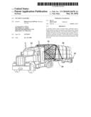
[0007]FIG. 1 is a perspective view of a heavy truck with a security load bra constructed in accordance with a preferred embodiment of the present invention;
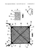
[0008]FIG. 2 is a front view of the security load bra;
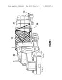
[0009]FIG. 3 is an exploded view of the interwoven material
DETAILED DESCRIPTIONS
[0010]As depicted in FIG. 1, the security load bra (10) attaches to the vehicle body (30) of a heavy semi-trailer truck (20). The vehicle body (30) is defined by a front cab structure (32) with a rearwardly attached flat bed platform trailer (34) supporting a secured heavy payload (36). In the transportation industry, flat bed plat form trailer (34) are used to transport large objects such as construction industrial machinery and other types of oversized objects. As depicted in FIG. 1, large objects such as pipes or logs can be secured as a payload (36). As depicted in FIG. 1, the security load bra 10 is positioned between the back side of the front cab (32) and the front side of the payload (36). Referring to FIG. 2, The security load bra 10 further comprises a plurality of interwoven straps (42, 41) forming a polygonal shape mesh structure capable of sustaining the forward momentum of an oversized payload of over 10 tons. As shown in FIG. 1, each strap (17) is capable of securing at least 5000 pounds of payload on a truck and is made of an elongated strip of strong material of a predetermined width and length. In the preferred embodiment, each strap is made of a strong, flexible, durable material with some measure of elasticity such as nylon or another suitable natural fiber or polymer based synthetic fiber. Additionally each strap can be made of a single or multiple layers of material and has a width of 4 inches. However, in the alternative, mesh structure can be scaled downward to support less payloads. For example the payload can be scaled backward to 2500 pounds by using a strap of two inches in width.
[0011]In yet, other embodiments, the corners can be re-enforced with a unibody triangular shape reinforcement device. This device can be made of
[0012]In the preferred embodiment, the perimeter of mesh structure 15 comprise top horizontal edge 50, bottom horizontal edge 52, left vertical edge 54, and a right vertical edge 56. Mesh structure 15 further comprises left top corner 58, opposing right top corner 60, left bottom corner 62 and opposing right bottom corner 64. In the preferred embodiment, mesh structure (15) is a square of 8 feet by 8 feet. However, mesh structure (15) is not limited to these dimensions. Mesh structure 15 further comprises a first subset of straps 40 and a second subset of straps 42. First subset of straps 40 extends across the body of the straps in one direction. Second subset of straps 42 extends across the body in the opposite direction interwoven in a criss-cross arraignment with first subset of straps 42 forming the interior body of mesh structure 15.
[0013]In the preferred embodiment the strapped mesh structure (15) has a polygonal shape preferably in either a square shape or rectangular shape. However, the security load bra 10 is not limited to that particular shape. As depicted in FIG. 2, each edge is secured with an additional horizontal strap secured thereto.
[0014]With other embodiments, each edge of the polygonal mesh structure 15 would have to be secured and the circumference of a circular or oval shape mesh structure would have to be secured 15. Additionally, diagonal straps (72,70) as discussed below could be situated in any type of polygonal or circular type structure.
[0015]Additionally, as depicted in FIG. 2, mesh structure (15) can be reinforced by first diagonal strap 70 and second diagonal strap 72. First diagonal strap 70 extends from top left corner 58 diagonally across the body of mesh structure 15 to bottom right corner 64. Second diagonal strap 72 extends from top right corner 60 diagonally across the body of mesh structure 15 to bottom left corner 62. First diagonal strap 70 overlays and second diagonal strap 72 the center forming a reinforcement vertex point (63) in the center of the body of mesh structure 15. Top horizontal edge 50, bottom horizontal edge 52, left vertical edge 54 and right vertical edge 56 are secured with a single or double layered strap to form a fully secured body. First diagonal strap 70 and second diagonal strap 72 can extend a predetermined distance beyond each corner forming securing means for attaching the mesh structure 15 into position around the front of the payload. The diagonal straps can be secured by sewing or any suitable adhesive type of material.
[0016]At each corner of the mesh structure 15, first diagonal strap 70 and second diagonal strap 72 extends a predetermined distance beyond each corner forming a extension top left 81, extension top right 82, extension bottom left 83, and extension bottom right 84. Left bottom extension 83 and right bottom extension 84 extends a shorter distance than left top extension 81 and right top extension 82 extends. An extension can be situated at each corner or a variation thereof. As shown, in the preferred embodiment fasteners such as hooks can be secured to the bottom right extension 83 and bottom left extension 84.
[0017]Referring to FIG. 1, there is shown device 10 attached in operational use. As shown, the top left extension 81 and the top right extension 82 are pulled downward and secured to the ratchet that is attached on opposing sides of the trailer bed frame. The bottom left extension 83 and the bottom right extension 84 are pulled forward and the fasteners are attached to the frame on opposing sides of the trailer bed frame.
[0018]In alternative embodiments the load bearing strap device can be build to scaled downward. For example, the load bearing straps can be down scaled to two inches in width capable of handling 2500 pounds. Additionally, the corners can be reinforced with a polygonal shape device securely attached thereto. In the preferred embodiment as shown in FIG. 2 one or each corner can be reinforced with a triangular shape reinforcement device which can be made of fabric, metal, plastic, or another suitable device.
User Contributions:
comments("1"); ?> comment_form("1"); ?>Inventors list |
Agents list |
Assignees list |
List by place |
Classification tree browser |
Top 100 Inventors |
Top 100 Agents |
Top 100 Assignees |
Usenet FAQ Index |
Documents |
Other FAQs |
User Contributions:
Comment about this patent or add new information about this topic:
Images included with this patent application:
 |  |
 |
| Similar patent applications: | |
| Date | Title |
|---|---|
| 2014-03-06 | Method for securing a motor vehicle to a transporter |
| New patent applications in this class: | |
| Date | Title |
|---|---|
| 2016-05-26 | Monkey grabs cargo hold |
| 2015-10-22 | Cargo net and related method of use |
| 2015-02-12 | Load restraint strip |
| 2014-08-28 | Multi-function winch system for securing cargo to a transport vehicle |
| 2014-03-13 | Linkable rope assembly |
| Top Inventors for class "Freight accommodation on freight carrier" | |
| Rank | Inventor's name |
|---|---|
| 1 | John D. Anderson |
| 2 | Walter J. Peach |
| 3 | Michael K. Burke |
| 4 | Jerrell P. Squyres |
| 5 | Jean-Marc Girardin |