Patent application title: INFLATABLE ELEMENT FOR INTERNAL USE IN THE CONTAINER OF A TRANSPORT OR STORAGE DEVICE; METHOD FOR INFLATING THE ELEMENT
Inventors:
Erik Jeroen Eenkhoorn (Hengelo, NL)
IPC8 Class: AB65D9000FI
USPC Class:
220723
Class name: Container attachment or adjunct expanding or contracting portion or component internal bladder-like bag for contents
Publication date: 2009-12-24
Patent application number: 20090314790
Inventors list |
Agents list |
Assignees list |
List by place |
Classification tree browser |
Top 100 Inventors |
Top 100 Agents |
Top 100 Assignees |
Usenet FAQ Index |
Documents |
Other FAQs |
Patent application title: INFLATABLE ELEMENT FOR INTERNAL USE IN THE CONTAINER OF A TRANSPORT OR STORAGE DEVICE; METHOD FOR INFLATING THE ELEMENT
Inventors:
Erik Jeroen Eenkhoorn
Agents:
KNOBBE MARTENS OLSON & BEAR LLP
Assignees:
Origin: IRVINE, CA US
IPC8 Class: AB65D9000FI
USPC Class:
220723
Patent application number: 20090314790
Abstract:
The invention relates to an inflatable element (4) (also indicated as
airbag) for use interiorly in a holder (2), the holder being suitable for
storing or transporting a liquid load, whereby the inflatable element is
provided with a accordion partition or otherwise stretchable or
elastically foldable wall or walls (7, 11, 20) which fold in or out or
stretch and shrink respectively by supplying or discharging inflating gas
into or from the inflatable element (4).Claims:
1. Inflatable element for use internally in a holder, the holder being
suitable for storing or transporting a liquid load, wherein the
inflatable element is provided with an accordion partition or otherwise
stretchable or elastically foldable wall or walls, which fold in or out
or stretch and shrink respectively by supplying or discharging inflating
gas into or from the inflatable element, in such a way that in an use
position the inflatable element is provided with such a size that the
volume of the liquid load plus the volume of the inflatable element is
essentially equal to the internal volume of the holder, whereby the
absolute pressure in the inflatable element is not substantially higher
than ambient pressure plus the static pressure exerted by the static
liquid height win a completely filled holder, so that as a result said
pressure remains below the design pressure of the holder and/or below a
set pressure of a safety valve of the holder.
2. Inflatable element according to claim 1, wherein the accordion partitions comprise of a super elastic material, whereby the volume of the space surrounded by the material is increased at least by a factor three when the internal pressure in the element is increased with a pressure equivalent to the static liquid height of a completely filled holder.
3. Inflatable element according to claim 1, wherein the inflatable element in inflated position has a shape corresponding to the internal shape of the free space in the holder filled with liquid load, in such a way that the walls are close-fittingly contacting the interior wall of the holder and the top surface of the liquid load.
4. Inflatable element according to claim 1, wherein the exterior walls in a use position are in tension.
5. Inflatable element according to claim 1, wherein, the inflatable element comprises at least two compartments.
6. Inflatable element according to claim 5, wherein the first compartment is positioned upon the upper side of the second compartment such that in use in the holder the first compartment is substantially contacting the interior wall of the holder and the second compartment is substantially contacting the upper surface of the liquid load.
7. Inflatable element according to claim 5, wherein the first and the second compartment each are adapted to receive or discharge inflating gas to or from the inflatable element.
8. Inflatable element according to claim 5, wherein the first compartment is connected with an external inflating means and the second compartment is connected with the first compartment by means of an internal inflating means in such a way that by supplying inflating gas into the first compartment firstly the foldable or stretchable wall will fold open, and secondly by means of the internal inflating means the inflating air is supplied into the second compartment.
9. Inflatable element according to claim 5, wherein the second compartment is configured by a wall provided between the outer ends of the first compartment and by the interior accordion wall of the first compartment.
10. Inflatable element according to claim 1, wherein the inflatable element comprises at least two element sections which are provided closely adjacently in the interior of the holder.
11. Inflatable element according to claim 10, wherein, two or more first compartments of adjacent elements sections are mutually connected and form a continuous compartment, while the adjacent second compartments, provided under the first compartments, are configured as element sections.
12. Inflatable element according to claim 10, wherein, internal inflating means are provided between the compartments of adjacent element sections.
13. Inflatable element according to claim 12, wherein, internal inflating means are provided between the second compartments of adjacent elements sections.
14. Holder for transporting a liquid load being provided with an inflatable element according to claim 1.
15. (canceled)
16. Method for inflating an inflatable element according to claim 8 in a holder of a transport or storage devices, comprising the following steps:inflating the inflatable element by supplying inflating gas to the first compartment by means of the external inflating means;inflating the second compartment of the element by supplying inflating gas from the first compartment to the second compartment by means of the internal inflating means.
17. Method for inflating an inflatable element according to claim 12, comprising:inflating the second compartment of an adjacent element section by supplying inflating gas from the second compartment of the first element section to the second compartment of the second element section by means of an inflating means provided between the elements sections.
Description:
[0001]The invention relates to an inflatable element (also indicated as
airbag) for use interiorly in a holder, the holder being suitable for
storing or transporting a liquid load, particularly for a holder of a
storage device like a tank container or a storage tank.
[0002]It is known that the cargo in transportable tanks (tank lorries) and road trucks due to various causes, e.g. by accelerating or speeding up or by braking or decelerating, by high speed in bends; or by swerving caused by (near) collisions, may exhibit an undesired dynamical behaviour which even may result in turning over of the vehicle. This effect is for a major part dependant upon the type of cargo contained in the storage tank, the truck or the tanker. For example free movable (low viscous) liquid will easily be brought into motion when subjected to a sudden manoeuvre of the tanker. The back and forth moving or sloshing of the liquid may supply an additional impulse force thereby accelerating turning over of the tanker or truck. Due to statutory regulations in order to prevent sloshing or oscillating of the liquid in the axial longitudinal or driving direction of the tank, baffle plates are mounted inside holders having a volume above a certain limit. These baffle plates have the disadvantage that they only damp axial liquid movements so that non-axial movement of the liquid, like radial or tangential movement, will not be damped or only to a small extend. Furthermore these plates have their own mass and volume, thereby decreasing the capacity of the holder. Moreover these plates are usually fixedly mounted inside the interior of the holder, so that labour-intensive interiorly mounting, inspection, repair en cleaning will be necessary. Furthermore the fixedly mounted plates inside the holder will transmit a portion of the impulse force and the energy of the oscillating liquid to the holder and the holder wall.
[0003]It is known that vapour is formed above the liquid surface depending upon the known physical liquid-vapour equilibrium and the resulting vapour pressure as a function of temperature. Particularly volatile liquids such as fuels, which have a high vapour pressure at ambient temperatures, will fill the free space of the holder with considerable amounts of the liquid load transported after the holder is emptied. The vapour will be continuously present when the liquid only partially fills the holder. Therefore it is not possible to discharge all of the loaded liquid because a portion thereof is evaporated into vapour and is not liquefied at the filling or discharge point. Furthermore it is known that vapour/air mixtures of fuels may easily explode particularly when stoichiometrically mixed, making extensive security measures necessary. The presence of air in the holder may furthermore be undesired because of possible deterioration of the quality of the transported load. Also measures must be taken against undesired emissions of vapour from the holder into the environment like the surrounding air.
[0004]It is known to introduce an inflatable bag, airbag or balloon into the interior of a holder and to inflate and pressurize it by means of e.g. a compressor with an inflating gas like air or with inflating gas from a high pressure reservoir or storage so that the balloon will fill a portion of the free space of the holder thereby reducing sloshing of the liquid and the formation of vapour. This is disadvantageous when the excess pressure in the balloon is greater than the static pressure exerted by the liquid load onto the bottom of the holder and situations could emerge whereby the holder wall is loaded with this excess pressure so that as a result the holder will be categorized as a pressure vessel. As a result the holder must meet the certification requirements for pressure vessels like thicker walls and the possibility for interior inspection. For existing holders like underground fuel tanks and tank trucks this is a great disadvantage because expensive additional measures inside the holder, like repositioning on the ground and/or mounting of pressure safety valves, become necessary when introducing an airbag. Another disadvantage of this known embodiment is that the high internal pressure in the balloon will more quickly result in the formation of leaking holes, so that air losses will occur. The balloon must be air tight at operating pressure. These inflatable balloons cannot easily be adapted to variations in the fill ratio of the load in the holder. It is almost impossible to fill the free space above the liquid with such a balloon for an almost empty or almost filled holder. Furthermore the wall of the balloon will be unevenly stretched when it touches the wall of the holder, while in the longitudinal direction all of the free space above the liquid is filled. Positioning of more than one inflatable bag into the holder shall only partly solve the stretch problems with changing fill ratio's. Furthermore is it difficult to provide precise close nearby positing of the individual bags so that individual control of the bags will be necessary.
[0005]Object of the invention is to provide an inflatable element which can be easily adapted to the free space above the liquid in the holder without applying high internal pressures, so that an anti-slosh devices as well as a reduction of the vapour space is realised.
[0006]This objective is achieved by the inflatable element being provided with an accordion partition or otherwise stretchable or elastically foldable wall or walls, which fold in or out or stretch and shrink respectively by supplying or discharging inflating gas into or from the inflatable element, in such a way that in use position--inflated position--the inflatable element is always provided with such a size that the volume of the liquid load plus the volume of the inflatable element essentially is equal to the internal volume of the holder, whereby the absolute pressure in the inflatable element is essentially not higher than ambient pressure plus the static pressure exerted by the static liquid height in a completely filled holder, so that as a result said pressure remains below the design pressure of the holder and/or below the set pressure of the safety valve of the holder. With abovementioned features the airbag may be easily adjusted to the changing shape and size of the free space above the liquid, while at the same time high pressures inside the holder are avoided. Furthermore the operating pressure in the inflatable element may be made equal to the static pressure in the holder. This allows for the required and wished self-control of the volume of the inflatable element. During filling and emptying of the holder the volume of the inflatable element will simultaneously increase or decrease by means of the inflating gas supply and the discharge valve which is controlled by means of the pressure inside the inflatable element. Herewith may also be automatically compensated for the changes of the volume of the liquid during transport by an opposite volume change of the inflatable element e.g. for use by fuel consumption of the vehicle during driving. As a result no information is needed about the pressure and/or the volume of the liquid load in the holder.
[0007]In an preferred embodiment the accordion partitions are consisting of a super elastic material, whereby the volume of the space surrounded by the material is increased at least by a factor three when the internal pressure in the element is increased with a pressure equivalent to the static liquid height of a completely filled holder. In this way it is possible that without applying high pressures in the inflatable element the holder may be filled with the inflatable element and moreover the volume of the elements may be easily adjusted to the changes in the liquid level of the load in the holder.
[0008]Preferably the inflatable element in inflated position is having a shape corresponding to the internal shape of the free space in the holder filled with liquid load, in such a way that the walls are close-fittingly contacting the interior wall of the holder and the top surface of the liquid load. By completely filling the free space above the liquid surface with the inflatable element evaporation of the liquid will not take place and the amount of vapour will be greatly reduced.
[0009]Preferably the exterior walls in use position are all provided with wall stretch-tension. Therefore the inflatable element will not be deformed by liquid movements in the holder so that liquid sloshing is strongly damped.
[0010]Particularly the inflatable element comprises at least two compartments and preferably the first compartment is positioned upon the upper side of the second compartment such that in use in the holder the first compartment essentially is contacting the interior wall of the holder and the second compartment essentially is contacting the upper surface of the liquid load. By these features an airbag is obtained which may be easily folded in or out and furthermore will damp liquid oscillations very well.
[0011]Particularly the first and the second compartment each are provided with inflating means for supplying or discharging inflating gas to or from the inflatable element; preferably the first compartment is connected with an external inflating means and the second compartment is connected with the first compartment by means of an internal inflating means in such a way that by supplying inflating gas into the first compartment firstly the foldable or stretchable wall will fold open, and secondly by means of the internal inflating means the inflating air is supplied into the second compartment. By these measures easily folding in and open of the airbag is obtained and furthermore only one inflating means, like an inflating hose, is necessary for two compartments.
[0012]Advantageously is the embodiment whereby the second compartment is configured by a wall provided between the outer ends of the first compartment and by the interior accordion wall of the first compartment. In this way the second compartment may be easily and at low costs be produced while moreover a good contact with the liquid surface is obtained and as a result thereof a good damping.
[0013]In a preferred embodiment the invention is characterized by the inflatable element consisting of at least two element sections which are provided closely adjacently in the interior of the holder; particularly two or more first compartments of adjacent elements sections are mutually connected and are constituting a continuous compartment, while the adjacent second compartments, provided under the first compartments, are configured as element sections. This embodiment having two inflatable elements in each holder will result in a considerable increase of the stability of the liquid load without having the need to attach the inflatable elements onto the wall of the holder. The inflatable elements will strive for the highest position in the holder and as a result deform at the mutual contact locations. Deformation of the inflatable elements does not allow for a common direction of rotation, so that the bag cannot roll or rotate over the inner wall of the holder in spite of the dynamic effects of the load acting upon the bags.
[0014]Possible is an embodiment with internal inflating means are provided between the compartments of adjacent element sections; preferably internal inflating means are provided between the second compartments of adjacent elements sections. With these feature an inflating element is obtained with an increased damping effect.
[0015]Furthermore the invention relates to a holder for use as transport means for a liquid load being provided with an inflatable element.
[0016]Furthermore the invention relates to a transport or storage device comprising a holder being provided with an inflatable element.
[0017]The invention also relates to a method for inflating an inflatable element in a holder of a transport or storage device, comprising the following steps: [0018]inflating the inflatable element by supplying inflating gas to the first compartment by means of the external inflating means; [0019]inflating the second compartment of the element by supplying inflating gas from the first compartment to the second compartment by means of the internal inflating means.Particularly the method further comprises the step: inflating the second compartment of an adjacent element section by supplying inflating gas from the second compartment of the first element section to the second compartment of the second element section by means of an inflating means provided between the element sections.
[0020]Advantageously by applying this method the airbag may be easily expanded and contracted inside the holder by changes of the load and the fill ratio.
[0021]The invention is further explained by means of a drawing of an embodiment of the inflatable element, whereby features and other advantages will come forward.
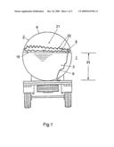
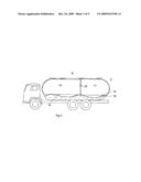
[0022]FIG. 1 shows in cross-sectional view a holder of a tank truck, provided with an inflatable element according to the invention;
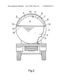
[0023]FIG. 2 shows in cross-sectional view the holder of FIG. 1, provided with an inflatable element having two compartments,
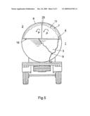
[0024]FIG. 3 shows a schematic cross-sectional side view of the holder, whereby the holder in longitudinal direction is provided with two inflatable element(s) (sections),
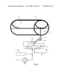
[0025]FIG. 4 shows the means for controlling the pressure in the inflatable element,
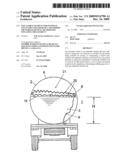
[0026]FIG. 5 shows in cross-sectional view the holder of FIG. 1 provided with two inflatable elements.
[0027]FIG. 1 shows a transport or storage device 1 provided with a holder 2. In this example the storage device is a tanker or tank truck 1, being provided with a holder 2 or tank and being configured for transporting of a liquid load 3. The holder 2 is about half filled with liquid 3, so that the liquid upper surface 16 is located approximately in the middle of the holder. On top of the upper surface 16 floats an inflatable element or airbag 4, which consists of foldable walls or accordion partitions 20. The airbag 4 is provided with inflating means 9, in this embodiment an inflating hose 9, which is leaded-through the bottom side of the wall of the holder. The inflating hose 9 is connected near the bottom side of the holder with inflating auxiliaries (not shown) like e.g. an air compressor and a control unit for supplying and discharging inflating gas like air or another gaseous product into or from the inflatable element 4. Furthermore control means like control lights are provided in the cabin of a cargo truck. Because the airbag 4 is provided with foldable walls 20 the airbag will easily increase in volume by supplying air, without having the need for a high and increasing internal pressure inside the airbag 4.
[0028]The airbag 4 consists of a single compartment between the accordion partitions(walls) 20. In the embodiment of FIG. 1 the airbag is provided with a relatively flat shape and fills only partially the free space 21 of the holder. As a result formation of liquid oscillations will be reduced or slowed down by the floating airbag 4 upon the liquid surface 16 and furthermore the sloshing movements of the liquid 3 in the holder 2 will be damped. This damping effect may be increased by further inflating and unfolding the airbag 4 so that the accordion wall 20 will contact the interior wall 8 of the holder. The airbag 4 being in inflated position or state will now completely fill the free space 21, so that vapour formation above the liquid is prevented.
[0029]The airbag described in the abovementioned example may also be used in non-moving or static holders like fuel tanks. Movement of the liquid will not be generated in this type of immovable holder so that sloshing or oscillating will not occur and no damping features are necessary for the airbag applied herein.
[0030]FIG. 2 shows in cross-sectional view the holder of the tanker 1 provided with an inflatable element 4 according to a second embodiment of the invention. In this embodiment the airbag 4 comprises two compartments 5, 6.
[0031]The first compartment 5 comprises foldable or accordion walls 7, 11 and the second compartment 6 herein is configured by the accordion wall 11 of the first compartment and by the third wall 14. The inflatable element 4 fills now entirely the free space in the holder while the third wall 14 is positioned nearby the free liquid surface 16 or is even contacting or floating upon the liquid surface. The first compartment 5 having accordion walls 7, 11 is configured above the second compartment 6, so that in inflated position the first compartment 5 with its first accordion wall 7 is engaging the interior wall 8 of the holder 2. Other combinations comprising more compartments provided with foldable walls are considered to be fall within the scope of the invention. The inflatable element 4 is provided with an inflating means 9; in this embodiment an inflating hose 9, which is leaded-through the wall 8 of the bottom side of the holder 2 is connected with inflating auxiliaries, like e.g. an air compressor. In this embodiment the inflating hose 9 is connected with the first compartment 5, but if required the inflating hose may also be connected with the second compartment or be connected with each compartment using separate hoses. By supplying inflating gas, like e.g. air, by means of the hose 9 into the first compartment 5, the accordion walls 7, 11 will unfold and the volume of the inflatable element 4 will be increased, without an substantial increase of the pressure in the 5, contrary to balloons of the known type. In FIG. 4 a preferred embodiment is shown of a pressure control assembly for control of the pressure in the inflatable element 4 of the holder 2. In this example the inflatable element 4 is provided with a (control) valve 31 connected with a pressure sensor 32 so that as a result of a measured low pressure a connection is made with compressor 35 of the inflating gas supply and as a result of a measured high pressure a connection is made with the inflating gas discharge 33. Instead of the use of a compressor for supplying the inflating air into the inflatable element 4 an high pressure inflating air reservoir 35 may be used. In the example as shown in FIG. 4 a safety valve 30 is mounted upon inflating means 9 between the control valve 31 and the inflatable element 4.
[0032]In the embodiment of FIG. 2 a second internal inflating means 10 is attached between the first and the second compartment. As a result firstly the first compartment 5 will unfold with the supply of air, while in second instance, by means of a slight surplus pressure in the first compartment, air is displaced from the first compartment into the second compartment. The configuration van FIG. 2 has the advantage that by supplying or discharging air firstly into or form the first compartment it will unfold or fold in along the interior wall 8 of the holder 2 so that always a close-fittingly filling of the free space of the holder 2 is guaranteed. In the embodiment of FIG. 2 the lower wall 14 nearby the liquid surface 16 is flat and smooth, so that as a result an improved damping effect is obtained of oscillations of the liquid in the holder. If desired three or more compartments may be provided in the inflatable element 4, or each compartment may be provided with separate, non-shared, foldable or unfoldable walls. In this embodiment of FIG. 2 the bottom wall 14 of the second compartment 6 is mounted upon the outer ends 12, 13 of the first compartment so that the bottom wall may easily take up a flat and smooth position with each fill ratio of the holder 2.
[0033]FIG. 3 shows schematically a cross-sectional side view of the holder 2 with inflatable element 4 consisting of two element sections 15, 17, which are axially mounted in longitudinal direction in the interior of the holder 2. Furthermore two element sections are shown in longitudinal direction, but other configurations having more element sections in axial or radial direction and other technical, for a person skilled in the art know, equivalent feature may be possible. The element sections may be separately mounted inside the holder 2; alternatively they may also be mutually connected.
[0034]A preferred embodiment consists of two or more (identical) inflatable elements positioned inside the holder, each element consisting of one or more compartments This embodiment is shown in FIG. 5 having two elements 4 being in mutual contact with side walls 25. The two or more inflatable elements 4 are striving for the highest position in the holder 2 and as a result will mutually deform each particularly there where they contact each other or the holder wall. The deformation of the inflatable elements 4 will not allow for a common direction of rotation of the elements according arrow P, so that the elements cannot roll or rotate over the inner wall 8 of the holder 2 in spite of the dynamic effects of the load 3 acting upon the elements.
[0035]Partitioning of the inflatable element provides for technical manufacturing advantages and renders mounting, inspection, repair and cleaning inside a large holder very easy. In an alternative embodiment the element sections each may be provided with compartments; it is advantageous to mutually connect adjacent first compartments having foldable walls into one big continuous compartment, while the lower positioned adjacent second compartments remain separated and do not form a big continuous compartment. As a result displacement of the air is prevented caused by sloshing and oscillating of the liquid and the damping effect of the inflatable element will increase. In an advantageous embodiment internal inflating means 22 are provided between the element sections in longitudinal direction of the holder 2, particularly between the second compartments, whereby the inflating means may be provided with a constriction for reduction of the gas flow. As a result, during oscillating of the liquid in the axial direction of the holder, gas may displace in opposite direction of the wave movement of the liquid, which will have an additional damping effect upon the sloshing liquid.
[0036]In FIG. 3 is schematically shown internal inflating means 22 located between two element sections 15, 17. In order to prevent and damp tangential or radial liquid oscillations in the holder 2 and to prevent turning over of the tanker truck, the internal inflating means may also be provided between the compartments of the in radial direction located element sections.
[0037]The inflatable element may be positioned unattached to the holder or may be (fixedly) connected with the holder; preferably the element is connected in such a way to the holder that ample forces are exerted upon the wall of the holder.
[0038]When in the description is mentioned "inflating" or "inflatable element" it includes all volume increasing systems having the same effect upon the solution of increasing the volume of an airbag without applying an high internal pressure.
[0039]The inflatable element may be manufactured from any suitable material like a plastic or fabric.
User Contributions:
comments("1"); ?> comment_form("1"); ?>Inventors list |
Agents list |
Assignees list |
List by place |
Classification tree browser |
Top 100 Inventors |
Top 100 Agents |
Top 100 Assignees |
Usenet FAQ Index |
Documents |
Other FAQs |
User Contributions:
Comment about this patent or add new information about this topic:
| People who visited this patent also read: | |
| Patent application number | Title |
|---|---|
| 20120241536 | Compositions and Methods for the Control of Nematodes and Soil Borne Diseases |
| 20120241535 | WATER ATOMIZATION AND MIST DELIVERY SYSTEM |
| 20120241534 | IRRIGATION LINE GUIDE AND METHOD OF IRRIGATING |
| 20120241533 | AGRICULTURAL SPRAYER AND METHOD |
| 20120241532 | Pyrethrin Based Repellant |
Images included with this patent application:
 |  |
 |  |
 |  |
| Similar patent applications: | |
| Date | Title |
|---|---|
| 2012-09-20 | Extension frame for a transport box or a pallet |
| 2012-04-19 | Cooler adapted for use in marine environment |
| 2012-12-06 | Fast freezer for bags with detection of the bag temperature |
| 2009-11-05 | Dust container of a hand-held power tool |
| 2010-03-11 | Labels, containers, system and method for providing reagents |
| New patent applications in this class: | |
| Date | Title |
|---|---|
| 2015-01-15 | Apparatus and method to limit slosh and ullage in a liquid container |
| 2015-01-08 | Apparatus and method to limit slosh and ullage in a liquid container |
| 2013-06-27 | Container having an inner bag |
| New patent applications from these inventors: | |
| Date | Title |
|---|---|
| 2014-09-04 | Element for eliminating turbulent behavior of liquid in a holder |
| Top Inventors for class "Receptacles" | |
| Rank | Inventor's name |
|---|---|
| 1 | Daniel Lee Bizzell |
| 2 | Frank Yang |
| 3 | Terry Vovan |
| 4 | William P. Apps |
| 5 | Lowell L. Wood, Jr. |