Patent application title: Linearly Displaceable Rotary Drive For A Plastic Injection-Molding Machine
Inventors:
Udo Schulz (Bad Neustadt, DE)
Assignees:
SIEMENS AKTIENGESELLSCHAFT
IPC8 Class: AB29C4503FI
USPC Class:
425574
Class name: Plastic article or earthenware shaping or treating: apparatus female mold and charger to supply fluent stock under pressure thereto in fluid-tight relationship (e.g., injection mold, etc.) with means to cause relative movement between mold and charger
Publication date: 2009-12-03
Patent application number: 20090297655
Inventors list |
Agents list |
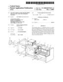
Assignees list |
List by place |
Classification tree browser |
Top 100 Inventors |
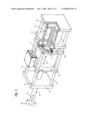
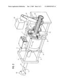
Top 100 Agents |
Top 100 Assignees |
Usenet FAQ Index |
Documents |
Other FAQs |
Patent application title: Linearly Displaceable Rotary Drive For A Plastic Injection-Molding Machine
Inventors:
Udo Schulz
Agents:
HENRY M FEIEREISEN, LLC;HENRY M FEIEREISEN
Assignees:
Siemens Aktiengesellschaft
Origin: NEW YORK, NY US
IPC8 Class: AB29C4503FI
USPC Class:
425574
Patent application number: 20090297655
Abstract:
The invention relates to a combination drive for a plastic
injection-molding machine having a rotary drive (1) for driving a screw
shaft (9) so as to rotate and a linear drive (2) for driving the screw
shaft (9) so as to perform a linear movement in the axial direction in
relation to the rotary drive (1). When the linear drive (2) performs a
linear movement, the rotary drive (1) is linearly entrained, thereby
avoiding any axial forces on the rotary drive (1).Claims:
1.-2. (canceled)
3. A drive for a plastic injection-molding machine, comprising:a rotary drive for driving a worm shaft to perform a rotation with the aid of a rotor; anda linear drive for driving the worm shaft to perform a linear movement in an axial direction in relation to the rotary drive,wherein the rotary drive being capable of being displaced linearly with the linear drive,wherein the rotary drive and the linear drive are arranged coaxially behind one another, andwherein the linear drive has a hydraulic cylinder, whose hydraulic piston is rigidly connected to the rotor of the rotary drive.
4. The drive of claim 3, wherein the rotary drive has an electric motor.
Description:
[0001]The present invention relates to a drive for a plastic
injection-molding machine having a rotary drive for driving a worm shaft
to perform a rotation and a linear drive for driving the worm shaft to
perform a linear movement in the axial direction in relation to the
rotary drive, the rotary drive being capable of being displaced linearly
by the linear drive. Such a drive is known from DE 198 52 513 B4.
[0002]In plastic injection-molding machines with a worm, the worm is moved in rotary fashion for the purpose of plastifying the plastic granules. The injection-molding process is achieved by a linear movement of the worm, which is typically realized by a hydraulic motor.
[0003]In this regard, the document DE 43 44 335 A1 has disclosed a corresponding injection-molding assembly for an injection-molding machine. This injection-molding assembly substantially comprises a worm cylinder, a worm and a worm drive comprising two electric motors, one electric motor being provided for the rotary driving and the other electric motor being provided for the axial movement of the worm. In order to achieve a compact design whilst simplifying the force transmission devices in the worm drive, the invention proposes arranging the two electric motors with their axes aligned with the axis of the worm, at least one electric motor being in the form of a hollow-shaft motor.
[0004]DE 101 35 516 A1 has disclosed a drive apparatus for the injection-molding unit of a plastic injection-molding machine which comprises an electromotive drive unit, which has a linearly movable output element and an electric motor, and a plurality of piston/cylinder units. The manner in which the piston/cylinder units function is very complex. A rotary drive acts at a point which is coaxially upstream of a first piston/cylinder unit.
[0005]The object of the present invention consists in proposing an alternative, possibly simpler drive for an injection-molding machine.
[0006]According to the invention, this is achieved by a drive for a plastic injection-molding machine having the features in accordance with patent claim 1.
[0007]According to the invention, the rotary drive and the linear drive are arranged coaxially one behind the other, and the linear drive has a hydraulic cylinder, whose hydraulic piston is rigidly connected to the rotor of the rotary drive. As a result, high linear forces can be transmitted to a worm without them acting on the rotary drive.
[0008]Preferably, the rotary drive has an electric motor and in particular a hollow-shaft motor. In particular, so-called torque motors having a very high torque are used for this purpose which make it possible to plastify the plastic granules.
[0009]The present invention will now be explained in more detail with reference to the attached drawings, in which:
[0010]FIG. 1 shows a perspective view of a drive according to the invention in accordance with a first embodiment, and
[0011]FIG. 2 shows a perspective view of a second embodiment of a drive according to the invention.
[0012]The exemplary embodiments described in more detail below represent preferred embodiments of the present invention.
[0013]The drive reproduced in FIG. 1 comprises a displaceable electric motor 1, which is in the form of a hollow-shaft motor, having a hydraulic cylinder 2 arranged behind it. The electric motor can be displaced corresponding to the arrow 3 by the hydraulic cylinder 2 in the axial direction of the electric motor.
[0014]Guide rods 4, which are fixed in guide plates 5, are used for guiding the electric motor 1 in its linear movement in the axial direction. The housing of the electric motor 1 has guide eyelets 6 on the motor plates, with which guide eyelets the electric motor 1 can slide onto the guide rods 4.
[0015]The rotor 7 of the electric motor 1 is rigidly connected to the piston 8 of the hydraulic cylinder 2. The movement of the hydraulic cylinder is therefore transmitted directly to the electric motor 1.
[0016]A worm shaft 9 is coupled to the rotor of the electric motor 1. As a result, it can be driven to perform rotary movements 10. Likewise, the linear movements 3 of the electric motor 1 are therefore transferred directly to linear movements 11 of the worm shaft 9.
[0017]A second embodiment of the present invention is reproduced in FIG. 2. In this case, too, the electric motor I is axially displaceable. This also takes place using the guide rods 4, on which eyelets 6 of the motor plates are mounted in sliding fashion.
[0018]The linear drive is in this case realized by a roller-type threaded drive including a threaded spindle 12 and a nut 13. The nut 13 is driven with the aid of a belt 14 and an electric motor 15. The nut 13 has a flange-like shape on one end side and is therefore supported on the inner ring of a bearing 16, which is incorporated in one of the guide plates 5. The bearing 16 is therefore designed such that it can also absorb axial forces.
[0019]The threaded spindle 12 is in turn rigidly connected to the rotor of the electric motor 1, with the result that the linear movement of the threaded spindle 12 is transmitted to the electric motor 1 and the worm shaft 9. In the event of a rotary movement of the rotary drive 1, the electric motor 15 for the linear drive also rotates in corresponding fashion.
[0020]In alternative embodiments, for example, the guide rods 4 can be replaced by corresponding linear drives, for example linear motors or hydraulic cylinders. As a result, installation space can be saved in the axial direction.
User Contributions:
comments("1"); ?> comment_form("1"); ?>Inventors list |
Agents list |
Assignees list |
List by place |
Classification tree browser |
Top 100 Inventors |
Top 100 Agents |
Top 100 Assignees |
Usenet FAQ Index |
Documents |
Other FAQs |
User Contributions:
Comment about this patent or add new information about this topic:
Images included with this patent application:
 |  |
 |
| Similar patent applications: | |
| Date | Title |
|---|---|
| 2013-06-20 | Abnormality detector for injection molding machine |
| 2013-06-20 | Nozzle-locating insulator having spring-noncontact sections interposed between spring-contact sections |
| 2013-06-20 | Knockout plunger for patty-forming machine |
| 2013-05-09 | Plant for production of plastic containers |
| 2010-11-11 | Antistatic silicone rubber mold-making material |
| New patent applications in this class: | |
| Date | Title |
|---|---|
| 2016-05-12 | Injection member attachment structure for injection molding machine |
| 2016-03-17 | Screw position adjustment device for injection molding machine |
| 2013-11-14 | Liquid resin molding system |
| 2013-02-21 | Mold-tool system including retractable support assembly to reduce support force to runner assembly |
| 2012-05-24 | Injection molding machine |
| Top Inventors for class "Plastic article or earthenware shaping or treating: apparatus" | |
| Rank | Inventor's name |
|---|---|
| 1 | Xiao-Ping Wu |
| 2 | Shih-Hsiung Ho |
| 3 | Denis Babin |
| 4 | Herbert Gunther |
| 5 | Chien-Feng Huang |