Patent application title: Up Spout 3D
Inventors:
Luke Helis (Riverside, CA, US)
IPC8 Class: AE03C104FI
USPC Class:
137801
Class name: Fluid handling faucets and spouts
Publication date: 2016-05-26
Patent application number: 20160145839
Abstract:
A faucet with a hidden spoutClaims:
11. A faucet comprising of a hidden, flexible spout combined with a cam
and spring actuation where forth used for selective spout positioning,
and to customize the reach of the spout and or the height of the spout
therewith, comprising of a cam body of plural bulges and plural deformed
projections with the bottom end making contact with a rotary cam with
plural projections moreover, both having a hollow center and being
inserted on a faucet body pipe mounted on a sink, comprising of a spring
coupled on its bottom end, and a cam bar formation of plural projections,
in between the plural projections is deformed; on the top of said faucet
body pipe said cam bars plural projections is not deformed in between,
blocking said cam body's plural bulges.
12. The faucet of claim 11, wherein said hidden, flexible spout is a malleable conduit coupled at its bottom end with a faucet hose that goes through said cam body, rotary cam, and spring, and on the top end said hidden, flex spout connecting to a spout of any volume or dimension.
13. A hidden, flex spout comprising of a malleable conduit coupled on the bottom end with a faucet hose, and on the top end coupled to a spout of any volume or dimension; furthermore, a cam body of plural bulges and plural deformed projections with the bottom end making contact with a rotary cam with plural projections wherein, both having hollow centers in which said faucet hose moves through, and both inserted inside a faucet body pipe mounted on a sink comprising of a spring coupled on its bottom end, and a cam bar formation of plural projections; in between the plural projection's is deformed; on the top of said faucet body pipe said cam bars plural projections is not deformed in between, blocking said cam body's plural bulges.
14. The embodiment of claim 14, wherein said faucet body pipe further comprising a coupling on its top end of a clamp that seizes or releases said hidden, flex spout 51.
Description:
FIELD OF THE INVENTION
[0001] The present invention relates to pull out faucets and faucets in general. There are currently no faucets in the market today that offer adjustability in length in both height and width. Also, most faucets have no way to change the position of a spout to leave it in a selective position. It is therefore an objective of the invention to provide a faucet with such means. Moreover, the faucet is relative with the prior art of a pull out faucet and therewith can be used as such while also comprising said selective positioning and total length adjustability.
BRIEF DESCRIPTION OF THE BACKGROUND
[0002] A faucet comprising a cam and spring actuation with a hidden, flexible spout. When said cam actuation is impeded by pushing down on said hidden flex spout it extends said hidden, flex spout. When said hidden, flex spout is put back in it's original position it will automatically lock itself. Said cam comprising of four main components in which are a spring, a cam body of deformed projections that forces a rotary cam of plural projections to switch and mate with a cam bar's plural projections.
BRIEF DESCRIPTION OF THE DRAWINGS
[0003] The objects, features, and advantages of the present invention will become apparent from the following detailed description of the preferred embodiment's and certain modifications thereof when taken together with the accompanying drawings in which like numbers represent like items throughout and in which:
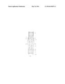
[0004] FIG. 1 Shows actuator of spout extension.
DETAILED DESCRIPTION OF THE EMBODIMENT
[0005] For the purposes of promoting an understanding of the principles of the invention, reference will now be made to the exemplary embodiment. The embodiment disclosed is not intended to be exhaustive or limit the invention to the precise form disclosed in the following detailed description. Rather, the embodiment is chosen and described so that others skilled in the art may utilize its teachings. It will be understood that no limitation of the scope of the invention is thereby intended.
[0006] A hidden, flexible spout comprising of a malleable conduit (e.g., a flexible metal conduit, such as an interlocked type-c tube), moreover coupled at the back end with a faucet hose 51a going to the water supply, and at the front-end coupled to a spout (not shown), the spout comprising of any desirable shape since hidden, flexible spout 51 can make said spout horizontal when out of said pipe 26. A cam bar of plural projections 45 is formed inside pipe 26, a spring 44 is coupled at the bottom end of said pipe 26; said pipe 26 is the spout mount, fastened to the sink (may also be coupled and fastened with a faucet plate) going under and on the sink, wherein said pipe 26 further comprises a plate to stay on said sink and wherein underneath threaded to secure it on said sink. A cam body with plural deformed projections 55 goes above rotary cam with plural projections 58. The cam body with plural deformed projections 55 further comprises plural bulges 23. In between the plural projections of the cam bar 45, is deformed 54, used as the plural bulges 23 canal 54. Said cam bar formation 45 can also be a sleeve coupled inside of pipe 26. The coupling of hidden, flex spout 51 and hose 51a is bulky (not exceeding the overall diameter of said cam body's deformed projections) used to push down on said cam body 55, that pushes down on said rotary cam 58, that pushes down on said spring 44. When said coupled cam body with plural deformed projections 55 with said operably coupled to it, rotary cam with plural projections 58 from said hidden, flex spout 51, pushes down on said compression spring 44, and passes said cam bars plural projections 45 of said pipe 26, it actuates its rotation and engages onto said projections of cam bar 45 of said pipe 26, which leaves the flex spout 51 in a locked hidden state and the spring compressed; said locked hidden state of the hidden, flex spout 51 can either be in a fully hidden or partially hidden locked state. Pressing down on said hidden, flex spout 51 once more induces rotation from said rotary cam with plural projections 58, disengaging from said cam bar with plural projections 45 of said pipe 26, causing decompression of said compression spring 44. On the top of pipe 26 said cam bars plural projections 45 is not deformed in between, blocking said cam body's plural bulges. Alternatively, the top end of pipe 26 may be coupled with a flange. Said cam bar plural projections 45 of said pipe 26 determines said hidden locked state of the hidden, flex spout 51. Pipe 26 may further comprise of a clamp 42 (which may be a counterpart of said alternative flange and or a counterpart of said plate that keeps said pipe 26 on top of a sink) coupling on its top end to lock a given length of said hidden, flex spout 51, although optional since said spring 44 will keep it up, but useful if said hidden, flex spout is long in length. Moreover, said clamp may comprise a variety of a lock handle (not shown), the likes of a twist handle, flip handle, or turn shaft lock handle. Spring 44, cam body 55, and rotary cam 58 are hollow in center to allow said faucet hose 51a to pass through. Spring 44 tension should be minimal. A hose weight cylinder fastener added to hose 51a will help significantly push down on said spring 44. Pipe 26 should be a vertical pipe with a longer diameter than pipe 26, and hidden, flex spout should be vertical when pushed down inside pipe 26 otherwise it will be difficult fitting in. The faucet valve/s should be mounted separately from pipe 26.
[0007] Lastly, said hidden, flex spout may be assorted in length to provide unique designs in a variable of prices.
[0008] Although the invention has been described in detail with reference to certain preferred embodiments, variations and modifications exist within the spirit and scope of the invention as described and defined in the following claims:
User Contributions:
Comment about this patent or add new information about this topic:
| People who visited this patent also read: | |
| Patent application number | Title |
|---|---|
| 20170174826 | DONOR-ACCEPTOR POLYMERS |
| 20170174825 | SYSTEMS AND METHODS FOR PRODUCTION OF ARTIFICIAL EUMELANIN |
| 20170174824 | METHOD OF FORMING A POLYMER COMPRISING A CONJUGATED BACKBONE |
| 20170174823 | AMINE-CATALYZED THIOL-CURING OF EPOXIDE RESINS |
| 20170174822 | RAPID CURING THIOL EPOXY RESIN WITH IMPROVED COMPRESSION STRENGTH PERFORMANCE |
Images included with this patent application:
 |  |
| New patent applications in this class: | |
| Date | Title |
|---|---|
| 2019-05-16 | Multi-function pull head |
| 2016-12-29 | Faucet valve housing assembly |
| 2016-06-23 | Valve body of a water faucet |
| 2016-06-09 | Mechanical touch faucet |
| 2016-05-26 | Faucet assembly |
| New patent applications from these inventors: | |
| Date | Title |
|---|---|
| 2016-12-29 | Aerobic and anaerobic device system for video game platforms. |
| Top Inventors for class "Fluid handling" | |
| Rank | Inventor's name |
|---|---|
| 1 | Nobukazu Ikeda |
| 2 | Kouji Nishino |
| 3 | Ryousuke Dohi |
| 4 | Kevin T. Peel |
| 5 | Huasong Zhou |