Patent application title: Low Profile Weapon Receptacle
Inventors:
Steven James Monroe (Jacksonville, FL, US)
IPC8 Class: AF41C3302FI
USPC Class:
224193
Class name: Carried by animate bearer article held by receiver handgun receiver having vertically extending side edges spaced apart or separable for withdrawal of handgun therebetween
Publication date: 2016-05-12
Patent application number: 20160131453
Abstract:
Low profile receptacle devices that removably receive at least one weapon
via a formed friction fit are disclosed. In an aspect, low profile
receptacle devices are disclosed that comprise at least one rigid or
semi-rigid sheet of material that makes the devices durable, reliable,
compact, ergonomic, highly concealable, and easy to use. Such low profile
receptacle devices may be worn on a user's belt via integration with at
least one belt loop.Claims:
1. A low profile weapon receptacle device configured to removably receive
at least one weapon, the device comprising: two elongated sheets of
semi-rigid material of uniform width, each comprising a central portion
and two opposing distal ends, and arranged as an outer sheet and an inner
sheet; at least one opening formed within the central portion of the two
sheets between the outer sheet and the inner sheet, the at least one
opening extending across the width of the at least one sheet; and at
least one fastener.
2. The device of claim 1, further comprising: at least one belt loop for securely receiving a portion of a belt; wherein the at least one belt loop is securely attached via the at least one fastener; and wherein the two sheets have a sheet width substantially equal to a belt width.
3. The device of claim 1, wherein the at least one opening is molded to removably receive at least one portion of the at least one weapon via a friction fit.
4. The device of claim 3, wherein the at least one weapon is a firearm.
5. The device of claim 4, wherein the at least one portion of the at least one weapon is at least one of: a barrel and a trigger assembly.
6. The device of claim 3, wherein the at least one opening exerts a tension retaining force on the removably received at least one weapon.
7. The device of claim 3, wherein the two sheets further comprises a bottom portion, the bottom portion comprising at least one lip configured to block at least a portion of the at least one opening preventing the at least one portion of the removably received at least one weapon from passing completely through the at least one opening by physically contacting the at least one portion of the at least one weapon.
8. The device of claim 1, wherein the at least one sheet is molded to fit the shape of a user hip.
9. The device of claim 1, wherein the material of the at least one sheet comprises a thermoplastic.
10. The device of claim 1, wherein the at least one belt loop is formed from a material that comprises a thermoplastic.
11. The device of claim 1, wherein the at least one fastener is at least one of: a screw, a bolt, a nail, and an adhesive.
12. The device of claim 1, wherein the device is configured to be lightweight.
13. The device of claim 1, the device comprising a degree of curvature.
14. The device of claim 13, wherein the outer sheet portion comprises a higher degree of curvature than the inner sheet portion.
Description:
CROSS-REFERENCE TO RELATED APPLICATIONS
[0001] This application claims the benefit, and is a continuation-in-part of Applicant's co-pending U.S. patent application Ser. No. 14/260,616 (Attorney Docket No. 3164.01) entitled "Mongo's Custom Bad Ass Holster," filed Apr. 24, 2014, the entire contents of which are incorporated herein by reference.
FIELD OF THE DISCLOSURE
[0002] The present disclosure generally relates to weapon holsters and more particularly to holsters with a low profile configuration.
BACKGROUND
[0003] The statements in this section merely provide background information related to the present disclosure and may not constitute prior art.
[0004] Holsters have long been used for carrying various types of weapons on one's person. Holsters allow for a weapon to be carried in an accessible fashion while still allowing one's hands to be free to do other things. Some of the biggest concerns associated with holster wear and use include utility, durability, comfort, and degree of concealability. Of course, these issues may mean different things to different users.
[0005] One group of frequent holster users includes military personnel. In a military setting, having proper access to one's weapon at any given moment can, and often does, mean the difference between life and death. Holsters that break and/or that fail to readily produce and/or receive a weapon can put a soldier in a life-threatening situation wherein a weapon, such as a handgun, goes missing and/or is not quickly and easily retrievable. Similarly, being able to properly store and/or conceal one's weapon can mean the difference between a peaceful encounter in enemy territory and an unwanted instigation of hostility. Of less consequence, but nevertheless important, is the comfort associated with carrying a weapon around all day. Soldiers that exert significant amounts of physical energy every day desire comfortable gear when it can be provided.
[0006] Several attempts have been made to provide users, such as military personnel, with holsters that are highly concealable and have a minimalistic, yet durable, design; however, the resulting products often fall well below user expectations. The provided holsters are often bulkier, more complex than necessary, and/or oddly shaped causing them to be uncomfortable or inefficient in use, easily broken, and/or configured such that it is difficult to insert or remove one's weapon from them, amongst other problems. Moreover, several types of holsters exist that include poorly designed straps, latches, locking mechanisms, and the like, which can impede fastidious weapon retrieval in the event of an emergency. Additionally, currently available holsters are often made of flimsy materials, such as leather, and therefore have less than optimal durability. As a result of these defects, many holsters provided to the military go unused and/or become quickly discarded, resulting in wasted funding and the potential hindrance of user safety.
[0007] Given the foregoing, holster devices are needed that allow weapon users, such as military personnel, to carry one or more weapons in a concealed, durable, and easily-accessible fashion. Additionally, hostler devices that are comfortable during long term wear are desired.
SUMMARY
[0008] This Summary is provided to introduce a selection of concepts. These concepts are further described below in the Detailed Description section. This Summary is not intended to identify key features or essential features of this disclosure's subject matter, nor is this Summary intended as an aid in determining the scope of the disclosed subject matter.
[0009] Aspects of the present disclosure meet the above-identified needs by providing receptacle devices for receiving one or more weapons, the receptacle devices being configured in a low profile format. Specifically, in an aspect, receptacle devices are disclosed that comprise at least one sheet of rigid and/or semi-rigid material, such as a thermoplastic. The sheet comprises an opening that is molded to receive at least one weapon via a friction form fit. In some aspects, especially when the material of the sheet comprises a thermoplastic, the compartment, via the configuration of the sheet of material, comprises a flexion-induced tension force based on the inherent flexing nature of the chosen material, such force helping to retain one or more weapons received therein. The sheet of material may be integrated with one or more belt loops in order to securely attach to a user's belt.
[0010] In some aspects, receptacle devices in accordance with the present disclosure comprise two sheets of rigid and/or semi-rigid material. In such aspects, the sheets may be configured adjacent to one another with the molded compartment formed between the sheets for receiving one or more weapons therein. Opposing distal ends of the two sheets may be securely held together via one or more fasteners.
[0011] In some additional aspects, the receptacle device of the present disclosure may be contoured to fit securely, comfortably, and closely against a user's hip. In such aspects, proper contouring may provide the user with more freedom of movement as well as help prevent the receptacle device from breaking as a result of user's awkward body positioning, such as the user is crouching, ducking, and/or crawling.
[0012] Further features and advantages of the present disclosure, as well as the structure and operation of various aspects of the present disclosure, are described in detail below with reference to the accompanying drawings.
BRIEF DESCRIPTION OF THE DRAWINGS
[0013] The features and advantages of the present disclosure will become more apparent from the Detailed Description set forth below when taken in conjunction with the drawings in which like reference numbers indicate identical or functionally similar elements.
[0014] FIG. 1 is a top view of a low profile weapon receptacle device, according to an aspect of the present disclosure.
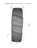
[0015] FIG. 2 is a front view of a low profile weapon receptacle device, according to an aspect of the present disclosure.
[0016] FIG. 3 is a rear view of a low profile weapon receptacle device, according to an aspect of the present disclosure.
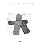
[0017] FIG. 4 is a front view of a low profile weapon receptacle device that has received a weapon, according to an aspect of the present disclosure.
[0018] FIG. 5 is a rear view of a low profile weapon receptacle device that has received a weapon, according to an aspect of the present disclosure.
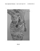
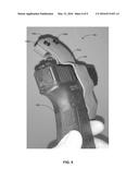
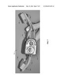
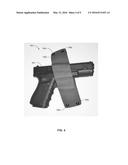
[0019] FIG. 6 is a perspective view of a low profile weapon receptacle device that has received a weapon, according to an aspect of the present disclosure.
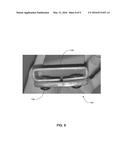
[0020] FIG. 7 is a bottom view of a low profile weapon receptacle device that has received a weapon, according to an aspect of the present disclosure.
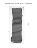
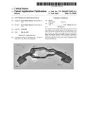
[0021] FIG. 8 is a side view of a low profile weapon receptacle device, according to an aspect of the present disclosure.
[0022] FIG. 9 is an image of a low profile weapon receptacle device being utilized by a user, according to an aspect of the present disclosure.
DETAILED DESCRIPTION
[0023] The present disclosure is directed to weapon receptacle devices that are configured to maintain a low profile when worn. Aspects of the present disclosure provide weapon receptacle devices that comprise a simplistic design using custom molded rigid and/or semi-rigid materials so as to facilitate ease of use, durability, reliability, and comfort associated with use and wear. Specifically, in an aspect, low profile weapon receptacle devices are disclosed wherein at least one sheet of material comprising a uniform width is formed to include at least one opening that is custom molded to securely receive at least one weapon via a friction form fit.
[0024] The term "receptacle" and/or the plural form of this term are used throughout herein to refer to any device capable of securely receiving at least one item for carrying, the device being attachable to a portion of an individual's person, a piece of apparel, and/or a functional item, such as a backpack, duffel bag, and the like. In some aspects, a "receptacle" may be a holster.
[0025] The term "user" and/or the plural form of this term are used throughout herein to refer to any individual who may need and/or desire to carry an item by utilizing the receptacle devices disclosed herein, particularly, but not only, when the item is a weapon, such as a handgun. Users may include military personnel, law enforcement officials, hunters, and the like.
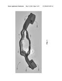
[0026] Referring now to FIG. 1, a top view of a low profile weapon receptacle device 100, according to an aspect of the present disclosure, is shown.
[0027] Receptacle device 100 may comprise at least one sheet 102 (shown as sheets 102a and 102b in FIG. 1), at least one opening 104, at least one fastener 106 (shown as fasteners 106a and 106b in FIG. 1), and at least one belt loop 108 (shown as belt loops 108a and 108b in FIG. 1).
[0028] Sheets 102 and belt loops 108 may comprise, at least in part, rigid and/or semi-rigid material so as to provide stability and durability to device 100. Additionally, such material may be pliable at very high temperatures in order to be formed and molded into custom designed shapes and sizes, thereby allowing device 100 to accommodate a variety of items within opening 104 and/or attach to a variety of different belt sizes via loops 108. In some aspects, sheets 102 and belt loops 108 are constructed to fit popular items and belt sizes. In some additional aspects, sheets 102 and belt loops 108 are formed with minimal customization, so as to enable a single device 100 to receive a variety of different weapons and/or belts.
[0029] By way of example and not limitation, the material used to make sheets 102 and/or belt loops 108 may comprise a thermoplastic, such as Kydex®, which is available from KYDEX, LLC of Bloomsburg, Pa. As will be appreciated by those skilled in the relevant art(s), the Kydex® may reach a significant level of pliability upon being heated to a very high temperature such as, by way of example and not limitation, approximately 350 degrees Fahrenheit. As will also be appreciated by those skilled in the relevant art(s) after reading the description herein, a variety of other materials may be used to construct sheets 102, loops 108, and/or any other component of device 100, including metals, other plastics, rubber, cloth, various other polymers, and the like. By way of example and not limitation, each sheet 102 may be approximately 20.32 cm long and 5.08 cm wide prior to any customization, while each belt loop 108 may comprise material that is 10.16 cm long and 1.91 cm wide.
[0030] Upon being heated to an appropriate temperature, the Kydex® and/or other material comprising sheets 102 may be custom molded to form opening 104, opening 104 extending across the width of a central portion of sheets 102. In some aspects, opening 104 is configurable to securely receive an item, which may include, by way of example and not limitation, a specific weapon 402 (not shown in FIG. 1), such as a handgun, via a friction induced form fit. Particularly, a portion of the barrel and/or trigger assembly of the handgun comprising weapon 402 may be received by opening 104; however, any portion of weapon 402 may be received by opening 104 as will be appreciated by those skilled in the relevant art(s) after reading the description herein. In forming opening 104, two sheets 102 may be used, adjacent to one another, or a single sheet 102 may be used, folded upon itself. In either case, device 100 comprises an outer sheet 102a and an inner sheet 102b.
[0031] In aspects wherein sheets 102 are comprised of at least one semi-rigid material, such material may comprise an inherent flexible tension property. That is, upon inserting weapon 402 into opening 104, outer sheet 102a may be pushed slightly away from inner sheet 102b, thereby causing the distance between outer sheet 102a and inner sheet 102b to increase, allowing for easier insertion of weapon 402. Once weapon 402 is fully received by opening 104, the distance between outer sheet 102a and inner sheet 102b may return to its smaller initial resting state, thereby tightening around weapon 402 in order to securely receive it and prevent its unintentional release from opening 104. Similarly, the flexible nature of sheets 102 may facilitate easier removal of weapon 402 from opening 104. By way of example and not limitation, weapon 402 may comprise a specific individual weapon to which opening 104 may be custom molded; a certain type of weapon, such a handgun, ammunition, knife, automatic or semi-automatic firearm; as well as a variety of other specific weapons and/or generic weapons as will be apparent to those skilled in the relevant art(s) after reading the description herein. Furthermore, other objects other than weapon 402 may be received by opening 104, including mobile cellular phones, portable electronic devices, and similar objects as will be appreciated by those skilled in the relevant art(s) after reading the description herein. In some aspects, device 100 may be integrated with one or more hooks, straps, snaps, buttons, protrusions, ridges, lips, crevices, locks, tabs, sliders, pins, or similar elements and/or structures that help keep weapon 402 secure within opening 104 in such a way so as to not diminish the simplicity and overall ease of use of device 100.
[0032] At opposing distal ends of device 100, fasteners 106 may hold sheets 102a and 102b together and/or securely attach belt loops 108. By way of example and not limitation, fasteners 106 may comprise screws, nuts, clips, rivets, washers, bolts, nails, pins, adhesives, or any other similar component as recognized by those skilled in the relevant art(s). In some aspects, fasteners 106 may comprise Kydex® screws that are securable within Kydex® screw inserts integrated with the opposing distal ends of device 100.
[0033] In aspects wherein device 100 comprises belt loops 108, loops 108 may be custom designed to fit securely around a specific belt. This may be accomplished by heating the material of loops 108 to an appropriate temperature, at which it may become pliable. Once pliable, the material may be formed around the actual belt to which device 100 may be attached. Various amounts of customization may be applied to loops 108, such that loops 108 may be formed to receive a specific belt, a certain type of belt, or one or more generic belts. In some aspects, device 100 may be substantially the same width as a given belt.
[0034] In some aspects, while the material of sheets 102 is in a pliable state, sheets 102 may be custom form fitted to fit the hip of a particular user 902 (not shown in FIG. 1), thereby facilitating a maximum level of comfort during wear. In alternative aspects, pliable sheets 102 may be formed so as to fit a generically determined hip size, or an approximated hip size for a user 902. In yet further aspects, sheet 902 may not undergo any form fitting process.
[0035] In some additional aspects, device 100 may be formed so that outer sheet 102a comprises a higher degree of curvature than inner sheet 102b. Such a configuration may allow for maximum comfort and concealment to be achieved for device 100 in that inner sheet 102b may be formed to fit comfortably, tightly, and securely upon user 902's hip while outer sheet 102a may be formed in significantly close proximity to inner sheet 102b, providing just enough room to create opening 104 between sheets 102a and 102b and therein securely receive weapon 402.
[0036] Referring now to FIG. 7, a bottom view of a low profile weapon receptacle device 100 that has received a weapon 402, according to an aspect of the present disclosure, is shown.
[0037] In some aspects, the bottom portion of at least one of sheets 102 may comprise securing lip 702 (labeled only as securing lip 702a in FIG. 7, for clarity). Lip 702 may prevent one or more received portions of weapon 402, such as the trigger assembly, from passing all the way through opening 104, thereby adding an extra retention element to device 100. Lip 702 may be formed as part of one or more sheets 102 or may be securely attached thereto. Lip 702 may comprise any material that may be used to construct device 100, including thermoplastic, metal, other plastics, rubber, cloth, various other polymers, and the like.
[0038] While various aspects of the present disclosure have been described above, it should be understood that they have been presented by way of example and not limitation. It will be apparent to persons skilled in the relevant art(s) that various changes in form and detail can be made therein without departing from the spirit and scope of the present disclosure. Thus, the present disclosure should not be limited by any of the above described exemplary aspects, but should be defined only in accordance with the following claims and their equivalents.
[0039] In addition, it should be understood that the figures in the attachments, which highlight the structure, methodology, functionality and advantages of the present disclosure, are presented for example purposes only. The present disclosure is sufficiently flexible and configurable, such that it may be implemented in ways other than that shown in the accompanying figures (e.g., transportation of other fluids or compositions of matter to inland hydraulic fracturing sites; utilization of transportation mechanisms and devices other than those mentioned herein). As will be appreciated by those skilled in the relevant art(s) after reading the description herein, certain features from different aspects of the systems, methods and computer program products of the present disclosure may be combined to form yet new aspects of the present disclosure.
[0040] Further, the purpose of the foregoing Abstract is to enable the U.S. Patent and Trademark Office and the public generally and especially the scientists, engineers and practitioners in the relevant art(s) who are not familiar with patent or legal terms or phraseology, to determine quickly from a cursory inspection the nature and essence of this technical disclosure. The Abstract is not intended to be limiting as to the scope of the present disclosure in any way.
User Contributions:
Comment about this patent or add new information about this topic:
Images included with this patent application:
 |  |
 |  |
 |  |
 |  |
 |  |
| Similar patent applications: | |
| Date | Title |
|---|---|
| 2015-05-14 | Low profile roof rail |
| 2015-04-16 | Open side wall mount rack |
| New patent applications in this class: | |
| Date | Title |
|---|---|
| 2015-02-12 | Holster with an inner anti-friction sleeve |
| 2014-02-20 | Holster |
| 2013-07-18 | Height and rotation adjuster for competition holster |
| 2012-09-06 | Lockable holster retention system |
| 2012-04-26 | Holster |
| Top Inventors for class "Package and article carriers" | |
| Rank | Inventor's name |
|---|---|
| 1 | Chris Sautter |
| 2 | Zac Elder |
| 3 | Peter Douglas Hubbard |
| 4 | Douglas Harland Murdoch |
| 5 | Jeffrey M. Aftanas |