Patent application title: Modular Shoe Sole Assembly for High Heels
Inventors:
Jessica G. Macfarlane (Maynard, MA, US)
IPC8 Class: AA43B1336FI
USPC Class:
36 15
Class name: Boots, shoes, and leggings sole-attaching means detachable soles
Publication date: 2016-04-07
Patent application number: 20160095386
Abstract:
A shoe sole assembly for increasing a bottom surface area of a high heel
shoe that includes a toe portion and a heel shaft having a bottom tip
includes a sole member having opposed front and rear ends that define a
generally planar surface therebetween. A heel receiving member is
situated on an upper surface of the sole member adjacent the rear end in
selective receipt of the bottom tip of the heel shaft of the high heel
shoe. A toe securement member is coupled to the sole member adjacent the
front end having a shape configuration in selective receipt of the toe
portion of the high heel shoe.Claims:
1. A shoe sole assembly for increasing a bottom surface area of a high
heel shoe that includes a toe portion and a heel shaft having a bottom
tip, said shoe sole apparatus comprising: a sole member having opposed
front and rear ends that define a generally planar surface therebetween,
said sole member having opposed side edges that together with said
opposed front and rear ends define a configuration substantially similar
to that of a human foot; a heel receiving member situated on an upper
surface of said sole member adjacent said rear end in selective receipt
of the bottom tip of the heel shaft of the high heel shoe; and a toe
securement member coupled to said sole member adjacent said front end
having a shape configuration in selective receipt of the toe portion of
the high heel shoe.
2. The shoe sole assembly as in claim 1, wherein said heel receiving member includes at least one upstanding wall defining an interior area that selectively receives the bottom tip of the heel shaft.
3. The shoe sole assembly as in claim 1, wherein said heel receiving member is a sleeve having an elongate configuration defining an open top in communication with said interior area and configured to receive the heel shaft of the high heel shoe therein.
4. The shoe sole assembly as in claim 1, wherein said toe securement member includes a right side end coupled to one of said side edges and a left side end coupled to another of said side edges, said toe portion includes a body portion extending upwardly relative to said sole member and extending between said side edges so as to define an interior space.
5. The shoe sole assembly as in claim 4, wherein said body portion defines at least an open back in communication with said interior space configured to receive the toe portion of the high heel shoe.
6. The shoe sole assembly as in claim 5, wherein said toe securement member is a closed toe shoe cover.
7. The shoe sole assembly as in claim 4, wherein said toe securement member is a flexible strap extending between respective side edges adjacent said front end of said sole member.
8. The shoe sole assembly as in claim 3, wherein said heel receiving member is coupled to the heel shaft in a friction fit engagement.
9. The shoe sole assembly as in claim 2, wherein said heel receiving member is configured to receive the heel shaft in a snap-fit engagement.
10. The shoe sole assembly as in claim 1, wherein said sole member includes a bottom surface having at least one tread portion configured to resist slipping or sliding when walking.
11. The shoe sole assembly as in claim 3, wherein said sleeve is coupled to said sole member with a flexible support frame that extends between an upper end of said sleeve to said sole member, said flexible support frame configured to prevent breakage of said sleeve when selectively received in said interior area.
12. The shoe sole assembly as in claim 11, wherein said flexible support frame includes at least one elastic band.
13. The shoe sole assembly as in claim 1, comprising an ankle support member operatively coupled to and situated above said heel receiving member, said ankle support member having an ankle receiving portion and a mounting portion extending between said ankle receiving portion and said heel receiving member.
14. The shoe sole assembly as in claim 13, wherein: said mounting portion includes a rod having a lower end coupled to said heel receiving member and an upper end coupled to said ankle receiving portion, said rod having an elongate and upwardly extending configuration; said ankle receiving portion includes a generally flexible strap having a closed back coupled to said upper end of said rod and defining an open front; sad ankle receiving portion having a fastener situated proximate said open front for selectively adjusting a degree of closure of said open front.
15. The shoe sole assembly as in claim 6, wherein: said mounting portion includes a rod having a lower end coupled to said heel receiving member and an upper end coupled to said ankle receiving portion, said rod having an elongate and upwardly extending configuration; said ankle receiving portion includes a generally flexible strap having a closed back coupled to said upper end of said rod and defining an open front; said ankle receiving portion having a fastener situated proximate said open front for selectively adjusting a degree of closure of said open front.
16. The shoe sole assembly as in claim 3, wherein: said mounting portion includes a rod having a lower end coupled to said heel receiving member and an upper end coupled to said ankle receiving portion, said rod having an elongate and upwardly extending configuration; said ankle receiving portion includes a generally flexible strap having a closed back coupled to said upper end of said rod and defining an open front; said ankle receiving portion having a fastener situated proximate said open front for selectively adjusting a degree of closure of said open front.
17. A shoe sole assembly for increasing a bottom surface area of a high heel shoe that includes a toe portion and a heel shaft having a bottom tip, said shoe sole apparatus comprising: a sole member having opposed front and rear ends having a planar surface extending therebetween and having opposed side edges arranged in the shape of a foot; a heel receiving member situated on an upper surface of said sole member adjacent said rear end that selectively receives the bottom tip of the heel shaft of the high heel shoe; and a toe securement member coupled to said sole member adjacent said front end having a shape configuration that selectively receives the toe portion of the high heel shoe.
18. The shoe sole assembly as in claim 17, wherein: said heel receiving member includes at least one upstanding wall defines an interior area that selectively receives the bottom tip of the heel shaft; said toe securement member is a flexible strap extending between respective side edges adjacent said front end of said sole member, said strap having a right side end coupled to one of said side edges and a left side end coupled to another of said side edges, said toe portion includes a body portion extending upwardly relative to said sole member and extending between said side edges so as to define an interior space.
19. The shoe sole assembly as in claim 17, comprising an ankle support member operatively coupled to and situated above said heel receiving member, said ankle support member having an ankle receiving portion and a mounting portion extending between said ankle receiving portion and said heel receiving member.
20. The shoe sole assembly as in claim 18, wherein: said mounting portion includes a rod having a lower end coupled to said heel receiving member and an upper end coupled to said ankle receiving portion, said rod having an elongate and upwardly extending configuration; said ankle receiving portion includes a generally flexible strap having a closed back coupled to said upper end of said rod and defining an open front; said ankle receiving portion having a fastener situated proximate said open front for selectively adjusting a degree of closure of said open front.
Description:
REFERENCE TO RELATED APPLICATIONS
[0001] This application claims the benefit of provisional patent application U.S. Ser. No. 62/058,636 filed Oct. 1, 2014 titled Simple Modular Device that Alters High Heels to a Flat Stable Surface and which is incorporated herein by reference.
BACKGROUND OF THE INVENTION
[0002] This invention relates generally to shoes and shoe accessories and, more particularly, to a modular shoe sole assembly that may be coupled to a high heel or stiletto type of shoe which provides a flat, stable sole so that a person can walk with smoothness and stability without removing her high heeled shoe from her foot.
[0003] High heeled shoes are often very uncomfortable or even painful if worn while walking any significant distance. Further, walking on sidewalks, pavement, rough or uneven surfaces may result in the high heel portion to break or cause the wearer to trip and fall.
[0004] Accordingly, a woman who must walk a distance to her workplace--even if just from her car to the office--often must bring a pair of "walking shoes" for walking in comfort and stability before changing into a more formal pair of shoes to wear while working. For instance, a woman who intends to wear high heeled shoes, e.g. stiletto shoes, may choose to wear flat shoes, e.g. tennis shoes, that are more stable and comfortable for walking and then change into the heeled shoes once arriving at the desired location.
[0005] Various devices have been proposed in the art for protecting high heeled shoes from damage or for protecting a wearer from discomfort. Although presumably effective for their intended purposes, the existing devices do not allow a wearer to continue to wear her normal shoes while protecting the shoes from damage and providing a flat and stable surface while walking on potentially uneven and unstable surfaces.
[0006] Therefore, it would be desirable to have a shoe sole assembly that is selectively attached to a pair of high heeled shoes and configured to provide a generally flat and stable surface while walking. Further, it would be desirable to have a shoe sole assembly that enables a user to walk comfortably and stably without first removing her high heeled shoes. In addition, it would be desirable to have a shoe sole assembly having a flat sole member, a heel receiving member, and a toe receiving member for securely mating with a high heeled shoe.
SUMMARY OF THE INVENTION
[0007] A shoe sole assembly according to the present invention for increasing a bottom surface area of a high heel shoe that includes a toe portion and a heel shaft having a bottom tip includes a sole member having opposed front and rear ends that define a generally planar surface therebetween. A heel receiving member is situated on an upper surface of the sole member adjacent the rear end in selective receipt of the bottom tip of the heel shaft of the high heel shoe. A toe securement member is coupled to the sole member adjacent the front end having a shape configuration in selective receipt of the toe portion of the high heel shoe.
[0008] Therefore, a general object of this invention is to provide a shoe sole assembly that converts a pair of women's high heel shoes into a flat, safe, and stable surface for comfort, safety, and longevity of the shoes. The modular shoe provides easy slip-on, slip-off convenience that can be attached quickly and stored easily for improved walking ability and shoe protection.
[0009] Another object of this invention is to provide a shoe sole assembly for increasing a bottom surface area of a high heel shoe that includes a toe portion and a heel shaft having a bottom tip.
[0010] Another object of this invention is to provide a shoe sole assembly, as aforesaid, that enables a wearer to walk with stability without first having to change out of a pair of high heels into a flat pair of shoes.
[0011] Still another object of this invention is to provide a shoe sole assembly, as aforesaid, that protects a pair of high heeled shoes from damage caused when walking on pavement, a sidewalk, rough, or uneven surfaces.
[0012] Yet another object of this invention is to provide a shoe sole assembly, as aforesaid, that is quick and easy to attach to or remove from a high heeled shoe.
[0013] Other objects and advantages of the present invention will become apparent from the following description taken in connection with the accompanying drawings, wherein is set forth by way of illustration and example, embodiments of this invention.
BRIEF DESCRIPTION OF THE DRAWINGS
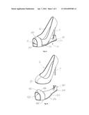
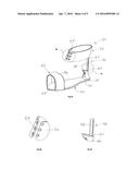
[0014] FIG. 1a is a perspective view of a shoe sole assembly according to an embodiment of the present invention in use with a high heel shoe;
[0015] FIG. 1b is an exploded view of the shoe sole assembly as in FIG. 1a;
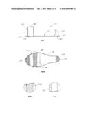
[0016] FIG. 2a is a front view of the shoe sole assembly as in FIG. 1a;
[0017] FIG. 2b is a sectional view taken along line 2b-2b of FIG. 2a;
[0018] FIG. 2c is an isolated view on an enlarged scale taken from FIG. 2b;
[0019] FIG. 2d is an isolated view on an enlarged scale taken from FIG. 2b;
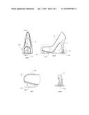
[0020] FIG. 3a is a side view of the shoe sole assembly as in FIG. 1a removed from the high heel shoe;
[0021] FIG. 3b is a bottom view of the shoe sole assembly as in FIG. 3a;
[0022] FIG. 3c is an isolated view on an enlarged scale taken from FIG. 3b;
[0023] FIG. 3d is an isolated view on an enlarged scale taken from FIG. 3b;
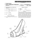
[0024] FIG. 4a is a perspective view of another embodiment of the present invention;
[0025] FIG. 4b is an isolated view on an enlarged scale taken from FIG. 4a;
[0026] FIG. 4c is an isolated view on an enlarged scale taken from FIG. 4a;
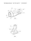
[0027] FIG. 5a is a perspective view of another embodiment of the present invention; and
[0028] FIG. 5b is an isolated view on an enlarged scale taken from FIG. 5a.
DESCRIPTION OF THE PREFERRED EMBODIMENT
[0029] A shoe sole assembly according to a preferred embodiment of the present invention will now be described with reference to FIGS. 1a to 5b of the accompanying drawings. The shoe sole assembly 10 includes a sole member 20, a heel receiving member 30, and a toe securement member 40.
[0030] The sole member 20 includes a front end 22 and a rear end 24 opposed to the front end 22 and having a generally flat (i.e. planar) surface extending therebetween. The sole member 20 also includes side edges 26 that, together with the front 22 and rear 24 ends define a shape configuration similar to that of a traditional shoe sole or human foot.
[0031] The heel receiving member 30 is situated on an upper surface of the sole member 20 proximate the rear end 24 thereof and may extend upwardly. In an embodiment, the heel receiving member 30 includes at least one side wall extending upwardly from the upper surface of the sole member 20. The at least one wall may be a continuous or cylindrical wall such that heel receiving member 30 is in the form of a sleeve or sheath that defines an interior area and an open top in communication with the interior area configured to receive the bottom tip of a heel shaft 7 of a high heeled shoe 6, such as a stiletto heel shoe. The heel receiving member 30 may have an elongate configuration configured to receive a substantial length of the heel shaft 7 (FIG. 5a). A longer length of the heel receiving member 30 is advantageous to stabilize and prevent damage to the heel shaft 7.
[0032] The heel receiving member 30 may be configured to selectively receive a heel shaft 7 and gently secure it in a friction-fit configuration. For example, the interior area may include a diameter that is substantially similar to a diameter of a heel shaft 7 of the high heeled shoe 6. In an embodiment, the heel receiving member 30 may include a construction and configured to receive and hold a heel shaft 7 in a snap-fit arrangement. To that end, the heel receiving member 30 may include an aperture and the heel shaft 7 may include a flange configured to engage the aperture in a selectively receivable and releasable (snap-fit) engagement (FIG. 2b).
[0033] In an embodiment, the elongate heel receiving member 30, i.e. the elongate sleeve described above, may include a support frame 52 that extends from an upper end of the heel receiving member 30 to the upper surface of the sole member 20. More particularly, the support frame 52 may have a flexible and resilient construction, such as a rubber band or other elastic structure (FIG. 5b). It is understood that the support frame 52 provides further support to the heel receiving member 30 and, consequently, decreases the risk that the heel shaft 7 of a high heeled shoe 6 will be damaged while walking.
[0034] The toe securement member 40 is coupled to the sole member 20 adjacent the front end 22 thereof. The toe securement member 40 is dimensioned and configured to selectively receive the toe portion 8 of a high heeled shoe 6 therein when the shoe sole assembly 10 is coupled to a high heeled shoe 6. The toe securement member 40 is important in making it possible for a wearer to walk using the shoe sole assembly 10 without first having to remove her high heeled shoes.
[0035] In an embodiment, the toe securement member 40 may be in the form of a flexible strap and includes a right side end 42 coupled to one of the side edges 26 and a left side end 44 couple to another of said side edges 26. Further, the toe securement member 40 includes a body portion 46 extending upwardly relative to the upper surface of the sole member 20 and between the respective side edges so as to define an interior space. The body portion 46 defines an open back dimensioned and configured to receive a toe portion 8 of a high heel shoe 6. In an embodiment, the toe securement member 40 is a closed-toe shoe cover having a configuration substantially the same as the closed-toe ladies shoe (not shown).
[0036] Although an open toe shoe is shown in the drawings, in another embodiment the bottom surface of the sole member 20 may include a tread portion 48 that is configured to resist slipping on a smooth surface on which a user may be walking. For instance, the tread portion 48 may be constructed of rubber or a rough-surface plastic and may be configured to create significant friction while walking.
[0037] In another aspect, the shoe sole assembly 10 may include an ankle support member 50 operatively coupled to the heel receiving member and positioned to selectively engage a wearer's ankle. More particularly, the ankle support member 50 includes an ankle receiving portion 52 and a mounting portion 56 that extends between the ankle receiving portion and the heel receiving member 30. The mounting portion 56 includes a rod 58 having a lower end 60 coupled to the heel receiving member 30 and an upper end 62 coupled to the ankle receiving portion 52. The rod 58 may have an upwardly extending configuration.
[0038] The ankle receiving portion 52 includes a generally flexible strap having a closed back coupled to the upper end of the rod 58 and defining an open front 54. In addition, the ankle receiving portion 52 includes a fastener 53 positioned proximate the open front 54 and is configured for selectively adjusting a degree of closure of the open front 54.
[0039] In use, a woman wearing high heel shoes may easily attach the shoe sole assembly 10 to her shoes and immediately continue walking with comfort and ease--as if walking in flats or other shoes with a flat sole. Specifically, the wearer can slide the toe portion of the high heel shoes into the toe securement member 40 and allow the heel shaft 7 of the high heel shoes 6 to rest in the heel receiving member 30 (FIG. 1a). In most cases, a user can couple the shoe sole assembly 10 to her shoes by just stepping into the sole member 20 positioned on the ground or a floor surface. Alternately, a user may remove her shoes, attach them to the sole member 20 as described above and then put the assembly on her foot. In some embodiments, the ankle receiving portion 52 may be secured for added support.
[0040] It is understood that while certain forms of this invention have been illustrated and described, it is not limited thereto except insofar as such limitations are included in the following claims and allowable functional equivalents thereof.
User Contributions:
Comment about this patent or add new information about this topic:
Images included with this patent application:
 |  |
 |  |
 |  |
| Similar patent applications: | |
| Date | Title |
|---|---|
| 2016-03-24 | Removable shoe sole system |
| 2016-03-10 | Welded shoe assembly |
| 2016-01-14 | Shoe sole simulating a hoof |
| 2016-03-31 | Sole shoe wearable over boot |
| 2016-04-28 | Shoe sole member |
| New patent applications in this class: | |
| Date | Title |
|---|---|
| 2019-05-16 | Exterior shoe attachement and method of use thereof |
| 2015-11-12 | Bowling shoe kit |
| 2014-07-17 | Device and related methods for coupling a shoe upper and shoe sole |
| 2013-08-15 | Footwear with separable upper and sole structure |
| Top Inventors for class "Boots, shoes, and leggings" | |
| Rank | Inventor's name |
|---|---|
| 1 | Frederick J. Dojan |
| 2 | Michael A. Aveni |
| 3 | Perry W. Auger |
| 4 | Sergio Cavaliere |
| 5 | Lee D. Peyton |