Patent application title: RELUCTANCE ARMATURE
Inventors:
Daniel Mader (Bad Neustadt An Der Saale, DE)
Rolf Vollmer (Gersfeld, DE)
Assignees:
SIEMENS AKTIENGESELLSCHAFT
IPC8 Class: AH02K328FI
USPC Class:
310208
Class name: Windings and core structure armature or primary coils
Publication date: 2016-03-24
Patent application number: 20160087501
Abstract:
A reluctance armature includes a shaft received in a shaft hole in a
torsion-proof manner. At least one carrier body is disposed around the
shaft and has radial sides as viewed in a circumferential direction. Part
segments are arranged on the radial sides of the carrier body and made of
anisotropic soft-magnetic material to thereby establish an armature
segment which, as viewed in an axial direction, is disposed between two
edge elements and forms a central section.Claims:
1. A reluctance armature, comprising: a shaft received in a shaft hole in
a torsion-proof manner; at least one carrier body disposed around the
shaft and having radial sides as viewed in a circumferential direction;
edge elements; and part segments arranged on the radial sides of the
carrier body and made of anisotropic soft-magnetic material to thereby
establish an armature segment which, as viewed in an axial direction, is
disposed between two of said edge elements and forms a central section.
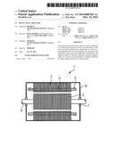
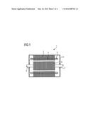
2. The reluctance armature of claim 1, wherein the edge elements are disk-shaped.
3. The reluctance armature of claim 1, further comprising further armature segments directly axially adjoining the central section in the axial direction, wherein each further armature segment is delimited by one or two of the edge elements.
4. The reluctance armature of claim 1, wherein the carrier body is of amagnetic configuration.
5. The reluctance armature of claim 1, wherein the carrier body is made of stainless steel, aluminum or plastic and/or has a spoke carrier structure.
6. The reluctance armature of claim 1, wherein the carrier body is connected to the shaft by a force fit and/or form fit.
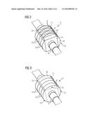
7. The reluctance armature of claim 1, wherein per pole of the reluctance armature at least one anisotropic soft-magnetic part segment is provided, which is of single-piece configuration and has different anisotropies in spatial directions of said part segment.
8. The reluctance armature of claim 3, wherein the armature segments have different angles of rotation in relation to one another to thereby create a staggering of a pole over an axial length of the reluctance armature.
9. The reluctance armature of claim 1, wherein the anisotropic soft-magnetic part segments are positioned and fixed by gluing to the carrier body and/or to the edge elements by an elastic adhesive.
10. The reluctance armature of claim 9, wherein the elastic adhesive is silicone.
11. A dynamoelectric machine, comprising a reluctance armature including a shaft received in a shaft hole in a torsion-proof manner, at least one carrier body disposed around the shaft and having radial sides as viewed in a circumferential direction, edge elements, and part segments arranged on the radial sides of the carrier body and made of anisotropic soft-magnetic material to thereby establish an armature segment which, as viewed in an axial direction, is disposed between two of said edge elements and forms a central section.
12. The dynamoelectric machine of claim 11, constructed of small shaft height and for comparably high rotation speed.
13. The dynamoelectric machine of claim 11, wherein the edge elements are disk-shaped.
14. The dynamoelectric machine of claim 11, further comprising further armature segments directly axially adjoining the central section in the axial direction, wherein each further armature segment is delimited by one or two of the edge elements.
15. The dynamoelectric machine of claim 11, wherein the carrier body is of amagnetic configuration.
16. The dynamoelectric machine of claim 11, wherein the carrier body is made of stainless steel, aluminum or plastic and/or has a spoke carrier structure.
17. The dynamoelectric machine of claim 11, wherein the carrier body is connected to the shaft by a force fit and/or form fit.
18. The dynamoelectric machine of claim 11, wherein per pole of the reluctance armature at least one anisotropic soft-magnetic part segment is provided, which is of single-piece configuration and has different anisotropies in spatial directions of said part segment.
19. The dynamoelectric machine of claim 14, wherein the armature segments have different angles of rotation in relation to one another to thereby create a staggering of a pole over an axial length of the reluctance armature.
20. The dynamoelectric machine of claim 11, wherein the anisotropic soft-magnetic part segments are positioned and fixed by gluing to the carrier body and/or to the edge elements by an elastic adhesive.
21. The dynamoelectric machine of claim 20, wherein the elastic adhesive is silicone.
22. The dynamoelectric machine of claim 11 for use in a machine tool, production machine or E-aircraft, such as helicopter, airplane, and traction drive of locomotive or streetcar, and E-car.
23. A method for manufacturing a reluctance armature, comprising: positioning a carrier body on a shaft; providing the carrier body at at least one axial end with an edge element; and placing and gluing a part segment made from anisotropic soft-magnetic one-piece material on a radial side of the carrier body segment or on a surface of the edge element to form an armature segment.
Description:
CROSS-REFERENCES TO RELATED APPLICATIONS
[0001] This application claims the priority of European Patent Application, Serial No. 14185534.6, filed Sep. 19, 2014, pursuant to 35 U.S.C. 119(a)-(d), the disclosure of which is incorporated herein by reference in its entirety as if fully set forth herein.
BACKGROUND OF THE INVENTION
[0002] The present invention relates to a reluctance armature, a dynamoelectric machine having such an armature, to the use of such a dynamoelectric machine, and to a method for manufacturing a reluctance armature.
[0003] The following discussion of related art is provided to assist the reader in understanding the advantages of the invention, and is not to be construed as an admission that this related art is prior art to this invention.
[0004] Reluctance armatures use different inductances of the laminated core in order to create a torque. In such cases the different inductances--the Ld and Lq axis--are created by punched-out areas in the laminated core. This punching out is conceivably unsuitable for smaller armature diameters and also for higher speeds, since the armatures deform through centrifugal force stress. Additional bandages to take up the centrifugal force stresses, especially with comparatively small dynamoelectric machines, would reduce the width of the air gap and would inter alia be a less efficient design of the machine.
[0005] It would therefore be desirable and advantageous to provide an improved reluctance armature for high-speed dynamoelectric machines, especially such machines with a low shaft height, to obviate prior art shortcomings and enable manufacture thereof in a simple manner while still exhibiting suitable electrical characteristics.
SUMMARY OF THE INVENTION
[0006] According to one aspect of the present invention, a reluctance armature includes a shaft received in a shaft hole in a torsion-proof manner, at least one carrier body disposed around the shaft and having radial sides as viewed in a circumferential direction, edge elements, and part segments arranged on the radial sides of the carrier body and made of anisotropic soft-magnetic material to thereby establish an armature segment which, as viewed in an axial direction, is disposed between two of the edge elements and forms a central section.
[0007] According to another aspect of the present invention, a dynamoelectric machine, includes a reluctance armature including a shaft received in a shaft hole in a torsion-proof manner, at least one carrier body disposed around the shaft and having radial sides as viewed in a circumferential direction, edge elements, and part segments arranged on the radial sides of the carrier body and made of anisotropic soft-magnetic material to thereby establish an armature segment which, as viewed in an axial direction, is disposed between two of the edge elements and forms a central section.
[0008] A dynamoelectric machine in accordance with the present invention is especially suitable for high speeds and small axis diameters.
[0009] According to still another aspect of the present invention, a method for manufacturing a reluctance armature includes the steps of positioning a carrier body on a shaft, providing the carrier body at at least one axial end with an edge element, and placing and gluing a part segment made from anisotropic soft-magnetic one-piece material on a radial side of the carrier body segment or on a surface of the edge element to form an armature segment.
[0010] The present invention resolves prior art shortcomings by using anisotropic soft-magnetic material so as to eliminate the need for a metal assembly of a reluctance armature. The term "anisotropic soft-magnetic material (awM)" is to be understood as a material which in one spatial direction has a comparatively poor magnetic conductivity (μr≦5) and in the other spatial directions has a comparatively good magnetic conductivity (μr≧20). The rare earths neodymium-iron-boron (Nd--Fe--Bo) form the basis of this material.
[0011] Thus one-piece poles of the reluctance armature or of an axial section of the armature are possible. In order to fasten these poles, sufficiently adhesive surfaces are provided on a carrier body which, at high speeds, in order to accept the centrifugal forces, are additionally glued in the axial direction to the edge elements. The segments of the anisotropic soft-magnetic materials are thus additionally glued to the edge elements adjoining them. Thus a maximum of three adhesive surfaces are present for each anisotropic soft-magnetic segment, one on the carrier body and two at the axial ends of this segment with the surfaces of the edge elements corresponding thereto.
[0012] According to another advantageous feature of the present invention, the carrier body is of amagnetic configuration. As a result, the carrier body does not contribute anything to the magnetic flux and guidance. For this reason, the carrier body can be constructed from stainless steel, aluminum or plastic. To reduce the inertia of the reluctance armature a spoke construction can also be provided as carrier body which however, like the other carrier body elements, must be connected to the shaft in a torsion-proof manner.
[0013] According to another advantageous feature of the present invention, the edge elements can be configured in the form of a disk. Suitably, the disk has a central hole for passage of the shaft.
[0014] Through a prespecifiable axial segmentation of a pole of reluctance armature and the simultaneous fitting of edge elements, the adhesive surface can be increased almost in any given way. This enables even higher centrifugal force stresses to be accommodated. Thus an adaptation to almost any, especially high (>10000 rpm) speed requirement of the dynamoelectric machine is possible.
[0015] Because of different thermal properties of the anisotropic soft-magnetic material and the carrier construction, an elastic adhesive, such as e.g. silicone, can advantageously be used.
[0016] According to another advantageous feature of the present invention, the carrier body can be connected to the shaft by a force fit and/or form fit in order to be able to transmit the torque from or to the shaft. The carrier body may also be connected to the shaft by a material-to-material bond. The shaft is likewise of an amagnetic design, i.e. especially with a relative permeability of μr<1.5.
[0017] According to another advantageous feature of the present invention, the shaft can be made of magnetic steel. In this case, the complete carrier body is made of amagnetic material, so that no magnetically-conductive connection with the shaft exists. A heating up of the shaft by eddy current losses is thus excluded.
[0018] By using amagnetic material for the carrier body between anisotropic soft-magnetic material and the shaft, the use of magnetic shafts rendered also possible so that costs of such a reluctance armature can be reduced.
[0019] A further advantage of the axially segmented rotor construction resides in the fact individual segments of a pole of the reluctance armature can be fastened about a pre-specifiable torsion angle to the shaft. Thus, for example, pendulum torques of the dynamoelectric machine are eliminated. For this purpose, it is necessary to construct the rotor in axial direction with at least from two segments disposed axially behind one another so that per pole a torsion angle can be provided.
[0020] According to a particular configuration in which for example the alternating current stator has 18 grooves, the segments are rotated in relation to one another by a stagger angle α=(1/n)(360°/18), wherein n is the number of the axial segments of the reluctance armature per pole.
[0021] By constructing the reluctance armature with structural gluing, the need for bandages in the air gap for holding together the reluctance armature can now be, advantageously, eliminated, leading to a higher utilization of the dynamoelectric machine, with utilization of the dynamoelectric machine to be understood as the torque delivered to the shaft per volume.
BRIEF DESCRIPTION OF THE DRAWING
[0022] Other features and advantages of the present invention will be more readily apparent upon reading the following description of currently preferred exemplified embodiments of the invention with reference to the accompanying drawing, in which:
[0023] FIG. 1 is a longitudinal section of a dynamoelectric machine;
[0024] FIG. 2 is a perspective view of a structure of a reluctance armature; and
[0025] FIG. 3 is a perspective view of a fully-assembled reluctance armature.
DETAILED DESCRIPTION OF PREFERRED EMBODIMENTS
[0026] Throughout all the figures, same or corresponding elements may generally be indicated by same reference numerals. These depicted embodiments are to be understood as illustrative of the invention and not as limiting in any way. It should also be understood that the figures are not necessarily to scale and that the embodiments are sometimes illustrated by graphic symbols, phantom lines, diagrammatic representations and fragmentary views. In certain instances, details which are not necessary for an understanding of the present invention or which render other details difficult to perceive may have been omitted.
[0027] Turning now to the drawing, and in particular to FIG. 1, there is shown a basic longitudinal section of a dynamoelectric machine, generally designated with reference numeral 1 and including a reluctance armature 5 and a stator 2. The stator 2 has a laminated stator core and a winding system 3, which is embedded in grooves 4, not shown in any greater detail, of the laminated stator core. Through electromagnetic interaction with a rotor which is embodied as a reluctance armature 5, a torque is transmitted to a shaft 6. As an alternative, when the dynamoelectric machine 1 is embodied as a generator, the torque is converted by the shaft 6 via the reluctance armature 5 in generator mode into electrical energy.
[0028] The shaft 6 is held in bearings 7 positioned in a bearing layer shield 8.
[0029] FIG. 2 shows a perspective view of a structure of the reluctance armature 5. The reluctance armature 5 includes a plurality of armature segments 13 (here four by way of example) which are disposed axially behind one another on the shaft 6. Each armature segment 13 includes a carrier body 11 and disk-shaped edge elements 9 which are between the individual carrier bodies 11. Positioned on radial sides 14 of each carrier body 11 are part segments 10 which are made of anisotropic soft-magnetic material. For ease of understanding, the radial side 14 of the carrier body 11 which points upwards has not yet been provided with a part segment 10, whereas the other sides 14 of the carrier body 11 are already provided with the individual part segments 10 made of anisotropic soft-magnetic material.
[0030] The placement of the individual anisotropic soft-magnetic segments 10 is realized by gluing to the radial sides 14 or surfaces of the carrier body 11 corresponding thereto and/or to the corresponding surfaces of the disk-shaped edge elements 9 corresponding thereto.
[0031] In addition the part segments 10 made of anisotropic soft-magnetic material can also engage into corresponding recesses on an edge 15 or lug of the carrier body 11 provided for this purpose and thus receive an additional radial and/or axial fixing and/or positioning.
[0032] FIG. 3 shows a fully assembled reluctance armature 5, in which an edge element 9 is provided on the end faces of the reluctance armature 5 and also between the individual axial sections, i.e. the armature segments 13. In the present exemplary embodiment no staggering of poles 12 and thus of the armature segments 13 by a pre-specifiable angle is carried out.
[0033] A staggering of the poles 12, viewed over the axial length of the armature 5, can however, be achieved during assembly by attaching each armature segment 13, comprised of carrier body 11 and, as in this case, four part segments 10 made of anisotropic soft-magnetic materials, offset by a pre-specifiable angle in circumferential direction on the shaft 6. The armature segments 13 are hereby separated from one another by the edge elements 9, with the part segments 10 also connected by a material-to-material joint, in particular glued, with the edge elements 9.
[0034] Applications of such a reluctance armature 5 and corresponding dynamoelectric machine 1 are particularly suitable for small motors/generators (shaft height about 15 to over 300 mm) with very high rotational speeds. Thus, these types of motors can be also be used in an E-car or E-aircraft, especially when the carrier body 11 is of a very light spoke-like carrier construction, so that the entire assembly (drive or generator) is comparably lightweight and thus guarantees a high power density and high utilization of the dynamoelectric machine 1.
[0035] While the invention has been illustrated and described in connection with currently preferred embodiments shown and described in detail, it is not intended to be limited to the details shown since various modifications and structural changes may be made without departing in any way from the spirit and scope of the present invention. The embodiments were chosen and described in order to explain the principles of the invention and practical application to thereby enable a person skilled in the art to best utilize the invention and various embodiments with various modifications as are suited to the particular use contemplated.
User Contributions:
Comment about this patent or add new information about this topic:
Images included with this patent application:
 |  |
 |
| Similar patent applications: | |
| Date | Title |
|---|---|
| 2016-06-16 | Stator for rotary electric machine and method for manufacturing the same |
| 2016-06-09 | Halbach array electric motor with substantially contiguous electromagnetic cores |
| 2016-06-16 | Piezoelectric thin film device and method for manufacturing the same |
| 2016-06-16 | Reluctance motor with virtual rotor |
| 2016-06-16 | Micro-electro-mechanical system device with enhanced structural strength |
| New patent applications in this class: | |
| Date | Title |
|---|---|
| 2022-05-05 | Stator winding arrangement |
| 2019-05-16 | Stator of rotating electric machine |
| 2018-01-25 | Insulating tapes for a coil and wrapping tape insulation systems for electric machines |
| 2017-08-17 | Stator of rotary electric machine |
| 2016-09-01 | Segment conductors, stator, rotating electrical machine, and vehicle and method of manufacturing the segment conductors |
| Top Inventors for class "Electrical generator or motor structure" | |
| Rank | Inventor's name |
|---|---|
| 1 | Bradley D. Chamberlin |
| 2 | Alex Horng |
| 3 | Rolf Vollmer |
| 4 | Michael D. Bradfield |
| 5 | Edward L. Kaiser |