Patent application title: HANDLING DEVICE FOR WEIGHT LIFTERS
Inventors:
John A. Schiek (Oshkosh, WI, US)
Assignees:
Schiek's Sports, Inc.
IPC8 Class: AA63B2100FI
USPC Class:
482 92
Class name: Exercise devices user manipulated force resisting apparatus, component thereof, or accessory therefor
Publication date: 2016-01-28
Patent application number: 20160023037
Abstract:
A handling device with an elongated flexible body, a receiving loop, and
first and second fasteners. The elongated flexible body has a first end,
a second end, a first terminal end, a top surface, and a bottom surface.
The receiving loop is formed at the first end by having the first
terminal end securely interconnected to a predetermined position on the
elongated flexible body to form an interconnection section on one of the
surfaces. The first fastener is securely attached to the elongated
flexible body on one of the surfaces and near the second end. The second
fastener is securely attached to the elongated flexible body on the same
surface as the first fastener and spaced apart from but near the second
end, so that the second fastener can be releasably attached to the first
fastener.Claims:
1. A device comprising: an elongated flexible body having a first end, a
second end, a first terminal end, a top surface, and a bottom surface; a
receiving loop formed at the first end by having the first terminal end
securely interconnected to a predetermined position on the elongated
flexible body to form an interconnection section on the top surface; a
first fastener securely attached to the elongated flexible body on one of
the top and bottom surfaces and at the second end; a second fastener
securely attached to the elongated flexible body on the same surface as
the first fastener and near but spaced apart from the second end, and
releasably attachable to the first fastener; the receiving loop having an
inner aperture that can receive the second end to form a wrist loop; the
wrist loop having an inner diameter that can receive a user's hand and
securely wrap to a user's wrist; the elongated flexible body having a
width and length that allows the elongated body to be wrapped about a
liftable object.
2. The device of claim 1 wherein the first and second fasteners are a hook and loop system.
3. The device of claim 1 wherein the predetermined position does not extend beyond the half-way point of the elongated flexible body.
4. The device of claim 1 wherein the second fastener is separated from the first fastener by a distance that is about double the width of the elongated flexible body.
5. A method of lifting an object comprising: obtaining a device having an elongated flexible body having a first end, a second end, a first terminal end, a top surface, and a bottom surface; a receiving loop formed at the first end by having the first terminal end securely interconnected to a predetermined position on the elongated flexible body to form an interconnection section on the top surface; a first fastener securely attached to the elongated flexible body on one of the top and bottom surfaces and near the second end; a second fastener securely attached to the elongated flexible body on the same surface as the first fastener and near but spaced apart from the second end, and releasably attachable to the first fastener; wherein (a) the receiving loop has an inner aperture that can receive the second end to form a wrist loop, (b) the wrist loop has an inner diameter that can receive a user's hand and securely wrap to the user's wrist, (c) the elongated flexible body has a width and length that allows the elongated body to be wrapped about a liftable object; inserting the second end into the receiving loop which has an inner aperture that can receive the second end; and releasably attaching the second fastener to the first fastener to thereby attach the second end to the first end.
6. The method of claim 5 wherein the first and second fasteners are a hook and loop system.
7. A device comprising: an elongated flexible body having a first end, a second end, a top surface, and a bottom surface; a receiving loop formed at the first end by having the first end folded over itself and securely connected to a predetermined position on the elongated flexible body to form an interconnection section on the top surface; a first fastener securely attached to the elongated flexible body on one of the top and bottom surfaces and at the second end; a second fastener securely attached to the elongated flexible body on the same surface as the first fastener and near but spaced apart from the second end, and releasably attachable to the first fastener; the elongated flexible body having a width and length that allows the elongated body to be wrapped about a liftable object.
8. The device of claim 7 wherein the first and second fasteners are hook-and-loop fasteners.
9. The device of claim 7 wherein the predetermined position is closer to the first end than to the second end of the elongated flexible body.
10. The device of claim 7 wherein the second fastener is separated from the first fastener by a distance that is about double the width of the elongated flexible body.
11. The device of claim 7 wherein the receiving loop is capable of receiving the second end such that the elongated flexible body forms a wrist loop; and the wrist loop has an inner diameter capable of receiving a user's hand and securely wrapping to a user's wrist.
12. The device of claim 7 wherein, in one usage, a remainder of the elongated flexible body is capable of being wrapped about an object merely by friction between the remainder and the object, and in another usage, the same device can have the first end and second end be securely fitted together and, in a user's palm, assist in holding the object by friction with the object and the user's palm.
Description:
FIELD OF THE INVENTION
[0001] The present invention relates to a device that assists a person to lift objects, such as bar weights.
BACKGROUND OF THE INVENTION
[0002] In the prior art, straps and other appliances used in facilitating enhanced gripping are known. None of these references disclose all of the features and aspects of the present invention.
[0003] Lifters are known to lift more than one type of bar with weights. Depending on the type of lifting being done, as well as the nature of the type of bar with weights, it is not uncommon for the lifter to need more than one type of handling device to assist with the lift. In one instance, a handling device may be a strap that is wrapped around the wrist and around the bar, in order to help in holding the bar. In other instances, a handling device may be a strap that is wrapped around the wrist and then looped over the bar, with a part of the looped over strap being held by simple friction between the bar and the palm of the hand of the lifter.
[0004] There is a need for improvements over the above described devices, and for solutions to the problems raised or not solved thereby.
SUMMARY OF THE INVENTION
[0005] The present invention relates to a handling device for use by weight lifters. The device has an elongated flexible body, a receiving loop, and first and second fasteners. The elongated flexible body has a first end, a second end, a first terminal end, a top surface, and a bottom surface. The receiving loop is formed at the first end by having the first terminal end securely attached to a predetermined position on the elongated flexible body to form an interconnection section on one of the surfaces. The first fastener is securely attached to the elongated flexible body on one of the surfaces and at the second end. The second fastener is securely attached to the elongated flexible body on the same surface as the first fastener and near but spaced apart from the second end. The second fastener releasably attaches to the first fastener.
[0006] One of the objects of this invention is to provide a single handling device that can be used in both instances. That is, the handling device of the present invention may be wrapped around the wrist and around the bar, in order to help in holding the bar, and alternatively, the same handling device may be wrapped around the wrist and then looped over the bar, with a part of the looped over strap being held by simple friction between the bar and the palm of the hand of the lifter.
[0007] Other objects and advantages of the invention will become apparent hereinafter.
BRIEF DESCRIPTION OF THE DRAWINGS
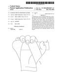
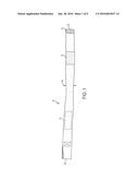
[0008] FIG. 1 is top view of a handling device for weight lifters according to a preferred embodiment of the present invention, in a generally flat position.
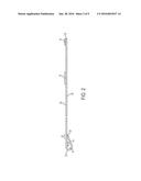
[0009] FIG. 2 is a schematic side view of the handling device shown in FIG. 1.
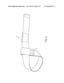
[0010] FIG. 3 is a top view of the device shown in FIG. 1, with a strap second end passing through a receiving loop at the device first end, with a length of strap available for wrapping around a bar to be lifted.
[0011] FIG. 4 is a bottom view of the device in the position shown in FIG. 3.
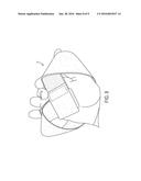
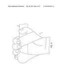
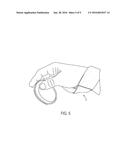
[0012] FIG. 5 is a side view of the device shown in FIG. 1, as it would be applied to a hand and wrist of a lifter, and wrapped around a bar to be lifted.
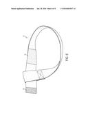
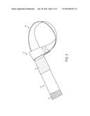
[0013] FIG. 6 is a top view of the device shown in FIG. 1, with the strap second end passing through the receiving loop at the device first end, with a short length of strap extending from the receiving loop.
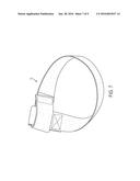
[0014] FIG. 7 is a top view of the device in generally the same position as shown in FIG. 6, except with the strap second end folded back over the strap and releasably secured to the strap, thereby forming a closed device.
[0015] FIG. 8 is a bottom view of the device shown in FIG. 7, as it would be positioned for holding a bar to be lifted.
[0016] FIG. 9 is a bottom view of the device shown in FIG. 8, with a hand and a bar in lifting position.
DETAILED DESCRIPTION OF THE PREFERRED EMBODIMENT
[0017] Referring to FIGS. 1 and 2, there is shown a handling device 10 for use with lifting an object 44 (see FIG. 9) in accordance with a preferred embodiment of the present invention. The handling device 10 includes a strap 12 having a receiving loop 14 formed at one end, a first fastener 16, and a second fastener 18.
[0018] In the most preferred embodiment, the strap 12 is made of fibrous material. Fibrous materials include, and are not limited to, natural and synthetic materials, such as cotton, wool, polymeric resins like polyester, or mixtures thereof. The strap 12 is an elongated flexible body having a first end 20, a second end 22, a first terminal end 24, a top surface 26, and a bottom surface 28. The strap 12 must have sufficient strength to sustain a force equivalent to, or preferably greater than, the force applied by a lifter to the mass of the lifted object.
[0019] The receiving loop 14 is formed at the first end 20 by having the first terminal end 24 securely attached to a predetermined position on the elongated flexible body 12 to form an interconnection section 30 on the top surface 26, as best shown in FIGS. 1, 2, and 4. A secure, relatively permanent, connection at interconnection section 30 may be obtained by conventional methods, preferably including but not limited to stitching. The predetermined position can be located anywhere along the elongated flexible body 12. Preferably, the predetermined position is between the first terminal end 24 and the half-way point of the elongated flexible body 12, and most preferably a distance away from the first terminal end that is just over twice the width W of the elongated flexible body.
[0020] Wherever the interconnection section 30 occurs, the resulting receiver loop 14 has an inner aperture IA equal to or greater than the width W of the elongated flexible body 12. The inner aperture IA must have such a size in order to permit the second end 22 to slip through the inner aperture IA to form a wrist loop 40, as shown in FIG. 3, without any buckling by the elongated flexible body 12.
[0021] The wrist loop 40 is adjustable to fit over a user's hand and secure to the user's wrist, as shown in FIG. 5. The remainder 42 of the elongated flexible body 12 extends from the wrist loop 40, so that, in one manner of use, the device 10 has a length of strap that can be wrapped around an object 44 (FIG. 9) to be lifted.
[0022] The first fastener 16 and the second fastener 18 are designed to releasably interconnect with each other. An example of such interconnection is a conventional hook-and-loop fastening system, where the first fastener 16 has the hooks, and the second fastener 18 has the loops. In an alternate embodiment (not shown), the first fastener 16 has the loops, and the second fastener 18 has the hooks. To make the connection between the first and second fasteners 16, 18, the first and second fasteners 16, 18 are on the same surface, whether that be the top surface 26 or the bottom surface 28.
[0023] The first fastener 16 is securely attached to the elongated flexible body 12 and, as just described, on one of the surfaces, by means of a secure, relatively permanent, connection, preferably including but not limited to stitching. Moreover, the first fastener 16 is positioned substantially at the second end 22 of the elongated flexible body 12.
[0024] Also as described above, the second fastener 18 is attached on the same surface as the first fastener 16, also by a secure, relatively permanent, connection, preferably including but not limited to stitching. But the second fastener 18 is positioned near but spaced apart from the second end 22. As a result, when the handling device 10 is used in a second manner, the second end 22 can be threaded through the receiving loop 14, and the second end can be folded back upon the elongated flexible body 12, with the first fastener 16 releasably attaching to the second fastener 18, so that the second end 22 becomes releasably secured to the first end 20 of the device.
[0025] The present invention assists the user to lift, or at least to apply force to, an object. The device 10 enables a user to maintain a firm hold on a bar, as illustrated in FIG. 9, in a manner that is much stronger than a user's fingers or the grip of a user's hand. In one usage, as shown in FIG. 5, the remainder 42 of the elongated flexible body 12 can be simply wrapped about the object. In another usage, the same device can have the connected first end 20 and second end 22 be securely fitted in the user's palm, as illustrated in FIG. 9. In either usage, the workload on the user's fingers and hand will be reduced, with the lifting forces transferred through the user's wrist to the larger muscles of the upper arm and upper body.
[0026] It is also known that when a user performs various lifts, the smaller muscles powering the user's fingers are exhausted long before the larger muscles of the upper arm and upper body are effectively worked. The device 10 allows a lifter to maintain a grip strongly enough to exhaust and train the larger muscles.
[0027] Thus a weight lifter no longer needs to carry two separate straps, one for use in the first manner where a loose portion of the strap is wrapped around a bar, and a second strap for use in looping over a bar, so the loop can be held in the hand between the palm and the bar. With the device of the present invention, when the first fastener is not secured to the second fastener, then the loose strap can be wrapped around a bar. And when it is desired to have a loop to wrap around a bar, the second end of the device can be releasably secured to the first end of the device, so the device can function in this fashion. As a result, the lifter now only needs to carry a single strap for each hand, and not the conventional two.
[0028] Although variations in the embodiment of the present invention may not each realize all the advantages of the invention, certain features may become more important than others in various applications of the device. The invention, accordingly, should be understood to be limited only by the scope of the appended claims.
User Contributions:
Comment about this patent or add new information about this topic:
Images included with this patent application:
 |  |
 |  |
 |  |
 |  |
 |  |
| Similar patent applications: | |
| Date | Title |
|---|---|
| 2015-10-22 | Freestanding selectable free weight assembly |
| 2016-04-21 | Training device having immediate training effect in water for swimmers |
| 2016-03-24 | Linear bearings and alignment method for weight lifting apparatus |
| 2016-01-21 | Muscular integral development system for resistance (midsyr) |
| 2016-03-17 | Training device for board sports |
| New patent applications in this class: | |
| Date | Title |
|---|---|
| 2018-01-25 | Mechanism for height and distance adjustment in pilates exercise equipment |
| 2016-07-07 | Body alignment and correction device |
| 2016-06-23 | Functional training rig kit |
| 2016-06-02 | Portable self contained slip cover that is remove ably attachable onto a torso pad associated with an exercise machine |
| 2016-05-26 | Modular multi-joint rehabilitation training system and method |
| Top Inventors for class "Exercise devices" | |
| Rank | Inventor's name |
|---|---|
| 1 | William T. Dalebout |
| 2 | Scott R. Watterson |
| 3 | Raymond Giannelli |
| 4 | Leao Wang |
| 5 | Bruce Hockridge |