Patent application title: EQUIPMENT FOR EXTRACTING AND INCREASING PRODUCTION OF CRUDE OIL AND GAS
Inventors:
IPC8 Class: AE21B4312FI
USPC Class:
166 68
Class name: Wells with below and above ground modification eduction pump or plunger in well
Publication date: 2016-01-14
Patent application number: 20160010435
Abstract:
The invention relates to equipment for extracting and increasing
production of crude oil and gas comprises: a connector unit connected to
a main piston axial, the main piston axial makes up and down movements
inside of a main cylinder; a piston unit connected to the connector unit,
the piston unit moves in connection with the main piston axial in order
to extract the extracting objects additionally; a cylinder unit creating
pressure to lift the extracting objects to the ground level as the piston
unit makes up and down movements inside of the piston unit; and a supply
unit managing the conveying process of the extracting objects by lifting
the extracting objects to the ground level when the piston unit moves up
and transporting the extracting objects to the storage when the piston
unit moves down.Claims:
1. An equipment for extracting and increasing production of crude oil and
gas comprising: a connector unit connected to a main piston axial, the
main piston axial makes up and down movements inside of a main cylinder
and the main cylinder is installed below the ground and exposed to
outside in order to extract extracting objects; a piston unit connected
to the connector unit, the piston unit moves in connection with the main
piston axial in order to extract the extracting objects additionally; a
cylinder unit creating pressure to lift the extracting objects to the
ground level as the piston unit makes up and down movements inside of the
piston unit; and a supply unit managing the conveying process of the
extracting objects by lifting the extracting objects to the ground level
when the piston unit moves up and transporting the extracting objects to
the storage when the piston unit moves down.
2. The equipment for extracting and increasing production of crude oil and gas of claim 1, the piston unit comprising: a piston axial connected to the connector unit but separated from the main piston axial, the piston axial makes up and down movements inside of the cylinder unit while exposed to the outside; a piston formed at the very bottom of the piston axial in a rounded board shape and makes and up and down movements inside of the cylinder unit; and top and bottom stoppers installed on the top and bottom of the piston axial assisting up and down movements of the piston axial inside of the cylinder unit by the pressure of the connector unit.
3. The equipment for extracting and increasing production of crude oil and gas of claim 2, the connection unit comprising: a clamp installed at the top of the main piston axial; a moving pipeline in a belt shape covering around the piston axial, the moving pipeline makes movements following the surface of the piston axial as the piston axial makes movements and presses the top and bottom stoppers; and a connector section connecting between the clamp and the moving pipeline, the connector section assists movements of the moving pipeline on the surface of the piston as the main piston axial makes up and down movements.
4. The equipment for extracting and increasing production of crude oil and gas of claim 2, the piston comprises a packing attached to an inner part of the cylinder unit covering the surface of the piston.
5. The equipment for extracting and increasing production of crude oil and gas of claim 1, the supply unit comprising: a sucking tube connected to the main cylinder, the sucking tube connects the cylinder unit and the main sucking tube thereby transporting the extracting objects to the ground level through the main sucking tube and the cylinder unit; an airflow tube connected to the main cylinder, the airflow tube connects the cylinder unit and the main airflow tube thereby transporting the extracting objects on the ground level to the storage; taps installed inside of the sucking tube and the airflow tube against each other in the opposite directions, the tap formed in the airflow tube closes the airflow tube when the tap formed in the sucking tube opens the sucking tube, and the tap formed in the airflow tube opens the airflow tube when the tap formed in the sucking tube closes the sucking tube as the piston unit moved up and down; and an extra airflow tube connected between the airflow tube and the sucking tube not to be interfered with any of the movements created by the piston unit when the amounts of the lifted extracting objects are over the volume of the cylinder unit.
6. The equipment for extracting and increasing production of crude oil and gas of claim 5, the tap comprising: a closing section having a dome shaped top; an opening section having a triangle shaped cross-sectional area formed at the bottom of the closing section; and a moving section connecting the closing section and the opening section, wherein the cross-sectional area of the moving section is smaller than that of the closing section and the opening section.
7. The equipment for extracting and increasing production of crude oil and gas of claim 6, further comprising: a sucking control section formed inside of the sucking tube, the sucking control section is provided between the closing section and the opening section of the sucking tube and the sucking control section has a sucking hole, which has a smaller diameter than the opening section and the closing section but has a greater diameter than the moving section in order to have the moving section moves around the sucking hole; and an airflow control section formed inside of the airflow tube, the airflow control section is provided between the closing section and the opening section of the airflow tube and the airflow control section has an airflow hole, which has a smaller diameter than the opening section and the closing section but has a greater diameter than the moving section in order to have the moving section 436 moves around the airflow hole 422.
Description:
TECHNICAL FIELD
[0001] The present invention relates to equipment for extracting and increasing the production of crude oil and gas and, more specifically, to equipment for extracting and increasing the production of crude oil and gas, which is capable of increasing the production of crude oil and gas without using additional power when crude oil and gas buried underground are extracted through a sucker rod.
BACKGROUND ART
[0002] The raw crude oil is a natural hydrocarbon mixture, being extracted from the oil layer from underground.
[0003] Through the fractional distillation process, this raw crude oil is separated into a few different fractions such as gasoline, kerosene, diesel oil, heavy fuel oil, etc. Each of these separated types of the oil is being very useful for many everyday needs in our lives.
[0004] This crude oil is deposited below the Earth's surface and the gas layer is in most cases located in the upper part of the oil layer as being formed by the gas generated from the crude oil.
[0005] For this reason, gas is usually expected to be extracted at the same time with the crude oil, and the sucker rod is used to pump this crude oil and gas.
[0006] By the sucker rod pumping unit, with the cylinder and piston rod, it is possibly utilized to lift the deposited crude oil and gas to the Earth's surface from underground by the piston making the repeated up and down strokes traveling inside of the cylinder.
[0007] The sucker rod pumping is a safe and conventional method to artificially lift out the crude oil. The world's most recognizable set of the system in this process is the sucker rod pumping system, especially the horse head and the walking beam for both underground and the Earth's surface.
[0008] Other than the gasoline and diesel engine, the components in the system used on the ground level are usually the prime mover to produce the rotation power, the gear reducer to get the needed speed and torque, the mechanical links like the walking beam to change movements from the rotation type to the piston type, the polished rod to connect the walking beam to the sucker rod string, and the pumping tee to off the process of packing the oil inside of the well and to remove the oil to the flow line for the storing process and also the following processes.
[0009] On the other hand, the down hole tools for underground includes the casing of the oil well, the tubing placed inside of the casing and used for extracting the oil, the rod string, built at the center of the tubing, with the sections of the sucker rod, for mechanical links needed between the down hole pump and polished rod, the moving ball valve, the pump plunger directly connected to the rod string for installing the liquid in the tubing, the stationed cylinder of the pump below the Earth's surface level, and the pump barrel with the stationed ball valve sucking the liquid into the barrel while the up strokes are being performed.
[0010] However, often this type of the sucker rods was considered as problematic in terms of the inefficiency in power consumption as it keeps a particular power level and amount throughout the entire mining processes being performed.
DISCLOSURE OF THE INVENTION
Technical Problem
[0011] The purpose of the productivity increasing equipment with the invention for extracting the crude oil and gas process is to enhance the capability of the system with the sucker rod, developed to produce greater volumes of oil and gas productions with the same amount of the power consumptions.
[0012] The purpose of the productivity increasing equipment with the invention for extracting the crude oil and gas process is to have the equipment possibly be simply attached onto and removed from any sucker rods, being expected to show the improved performances with producing more products.
[0013] The purpose of this productivity increasing equipment with the invention for extracting the crude oil and gas process is to minimize the amount of power used for the sucker rod and enhance the oil and gas extracting efficiency.
Technical Solution
[0014] This productivity increasing equipment with the invention for extracting the crude oil and gas process includes a few different units, such as a connector unit, attached to the main piston axial performing the up and down strokes in side of the main cylinder, exposed to outside, located underground, a piston unit to extract possibly an additional amount of the extracting objects as being attached to the connector unit and interlocking the main piston axial in the operations, the cylinder unit, producing the force to life the objects onto the ground level through the performances of the up and down strokes inside of the piston unit, and a supply unit, making the objects pushed into the storage after being lifted onto the ground level with utilizing the piston unit with the repeated up and down strokes.
[0015] The piston unit includes a piston axial, performing the repeated up and down strokes from inside to outside in the cylinder unit, attached onto the connector unit but separated from the main piston axial, a piston, formed in a rounded board shape, making the up and down movements inside of the cylinder unit, and the top and bottom stoppers, one on the top and the other on the bottom of the piston axial, and making the repeated up and down strokes possible with the piston axial by the pressures of the connector unit.
[0016] The connector unit includes a clamp, attached onto the top of the main piston axial, a moving pipe, generating the pressures onto the top and bottom stoppers in making the movements around the piston axial, having the main piston axial being attached onto and moving around the surface of the piston axial, and a connector section, having the movable pipe moving around the surface of the piston like the up and down movements of the main piston axial, connecting the moving pipe to the clamp.
[0017] The piston includes a packing, being stick to the inner part of the cylinder unit and wrapping the surface around the piston.
[0018] The supply unit includes a sucking tube, connected to the main sucking tube and cylinder unit, the main path of the extracting objects in lifting as being connected onto the main cylinder, the sucking tube, connected to the cylinder unit and the main airflow tube, connected to the main cylinder in order to force the objects into the storage after they have been lifted onto the ground level, and a tap, being removed to open the airflow tube when the sucking tube is open, and being closed when the airflow tube is closed as the piston unit moves up and down inside of the sucking tube and airflow tube, installed against each other in the directions.
[0019] The tap has a closing section of the dome shaped top, an opening section of the triangle shaped bottom of the cross-sectional area, and a moving section, connecting between the closing and opening sections but with a smaller the cross-sectional area than the closing and opening sections.
[0020] In the inner part of the sucking tube, between the closing and opening sections, there is an air sucking tap section, set up to have the moving section possibly making the movements around the air sucking hole with a smaller diameter than the opening and closing sections. In the inner part of the airflow tube, between the opening and closing sections, the airflow control section, to have the moving section possibly making the movements around the air sucking hole with a diameter greater than the moving section and smaller than the closing and opening sections.
Advantageous Effects
[0021] This productivity increasing equipment with the invention for extracting the crude oil and gas process has the technological impacts on increasing the productivity level with using the power created by the sucker rod.
[0022] This productivity increasing equipment with the invention for extracting the crude oil and gas process has the technological impacts on enhancing the performances as being attached to and removed from the sucker rod in the simple and easy way.
[0023] This productivity increasing equipment with the invention for extracting the crude oil and gas has the financial impacts on the performances as minimize the power consumption and maximize the efficiency of the crude oil and gas mining.
BRIEF DESCRIPTION OF THE DRAWINGS
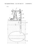
[0024] FIG. 1 is an illustration, an example application of the productivity increasing equipment with the invention for mining the crude oil and gas.
[0025] FIG. 2 is an illustration, a model of the productivity increasing equipment with the invention for mining the crude oil and gas.
[0026] FIG. 3 is an illustration, a performance example of the productivity increasing equipment with the invention for mining the crude oil and gas.
[0027] FIG. 4 is an illustration, a performance example of the productivity increasing equipment with the invention for mining the crude oil and gas.
[0028] FIG. 5 is an illustration, a core section of this productivity increasing equipment with the invention for mining the crude oil and gas.
[0029] FIG. 6 is an illustration, the object of FIG. 5 with the isometric view.
[0030] FIG. 7 is an illustration, an application example of the productivity increasing equipment with the invention for mining the crude oil and gas.
[0031] FIG. 8 is an illustration, another application example of the object of FIG. 7.
TABLE-US-00001
[0032] * Description of Reference Characters * 1: sucker rod 3: Earth's surface 9: storage 10: extracting object 20: motor system 30: main cylinder 32: main sucking tube 34: main airflow tube 40: crankshaft 50: main piston axial 60: walking beam 70: king post 80: saddle bearing 90: horse head 100: connector unit 110: clamp 120: moving pipeline 130: connector section 200: piston unit 210: piston axial 220: piston 230: top stopper 240: bottom stopper 250: packing 300: cylinder unit 310: airflow control hose 400: supply unit 410: sucking tube 412: sucking hole 415: sucking control section 420: airflow tube 422: airflow hole 425: airflow control section 430: tap 432: closing section 434: opening section 436: moving section 440: extra airflow tube
MODE FOR CARRYING OUT THE INVENTION
[0033] The following discussions will be helped with the enclosed figures given for reference for any possible performances in particular as examples of the invention in use. These performance examples will be detailed enough for individuals in the business to understand and use the invention. The performance examples do not need to be mutually exclusive but different from each other. For example, any single figure, structure or characteristic given for a particular discussion in the following will be possibly referred a performance example in another discussion within the scope and envisions in common. In addition, it should be in understanding clear that each part of the performance examples will be possible to be placed in different ways within the scope and envisions in common. Therefore, the details of the following discussions results no limitations in any meanings and the scope of the invention to be explained is that it should be the one to be affected the claim in each of the articles only.
[0034] Throughout the figures, the signs and marks will be used in coherence and correspondence with the one or another for the same or similar functions in particular, and the shapes, the length, the area and the height will be possibly magnified for the convenience.
[0035] In the following, the discussions will be detailed on the expected performance examples with the enclosed figures for reference in order to have the invention implemented by any individuals with the common knowledge in the indicated field of science and technologies.
[0036] In the following detailed discussions, the applications will be seen in coherence, fairly for the specified technological elements of this productivity increasing equipment with the invention for mining the crude oil and gas deposited underground using the sucker rod for example.
[0037] FIG. 1 is an illustration, a performance example of the productivity increasing equipment with the invention for extracting the crude oil and gas process.
[0038] FIG. 2 is an illustration, a model of the productivity increasing equipment with the invention for extracting the crude oil and gas process.
[0039] As FIG. 1 and FIG. 2, the sucker rod 1 is used to extract the objects 10, the crude oil and gas.
[0040] Among the mining objects 10, the crude oil is deposited below the Earth's surface and the gas is formed underground at the top of the crude oil.
[0041] The sucker rod 1 includes a main cylinder 30 exposed to the outside from below the Earth's surface 3, and a main piston axial 50 making the repeated up and down movements inside the main cylinder 30 in order to create the pressure to lift the extracting objects 10 to the ground level.
[0042] In addition, the sucker rod 1 includes a crankshaft 40 delivering the rotation movements made by the power of a motor system 20, a walking beam 60 connected to the crankshaft 40, and a king post 70 holding the walking beam 60.
[0043] Further, the sucker rod 1 includes a saddle bearing 80 making the walking beam 60 possibly be at the top of the king post 70 and perform the seesaw movements on the king post 70, and a horse head 90 making the main piston axial 50 possibly be connected to the walking beam 60 and perform the up and down movements.
[0044] Furthermore, the sucker rod 1 helps the mining objects 10, sucked into the top from below of the Earth's surface 3 with the sucking force, created from the up stroke movements of the main piston axial 50 inside of the main cylinder 30, and for this work a main sucking tube 32 is connected to the main cylinder 30.
[0045] Also, the mining objects 10 will be forced into a storage 9 located in the ground level by the pressures created from the down stroke movements of the main piston axial 50 inside of the main cylinder 30, and for this work a main airflow tube 34 is connected to the main cylinder 30.
[0046] The productivity increasing equipment with the invention for extracting the crude oil and gas process is to increase productivity with the additional amount of the objects, expected to be produced in using the power system of the sucker rod connected to the main piston axial 50.
[0047] For this work, a connector unit 100 is formed at the main piston axial 50.
[0048] A piston unit 200 is installed as being connected to the connector unit 100 and making the movements with the main piston axial 50 in cooperation, to be able to extract the objects 10.
[0049] Moreover, a cylinder unit 300 is installed to create the pressure to lift the extracting objects 10 with the up and down movements of the piston unit 200.
[0050] In addition, in the cylinder unit 300, a supply unit 400 is included to support the delivery process of the extracting objects 10 into the storage 9 when they lifted to above ground forced by the piston unit 200 making the up and down movements.
[0051] The connector unit 100 is being performed to have the piston unit 200 making the movement while the main piston axial 50 is making the repeated up and down movements as being connected to the piston unit 200 in one side and to the main piston axial 50 in the other side.
[0052] In addition, the piston unit 200 performs to create the pressures to force the extracting objects 10 to the storage 9 after they are lifted from the up and down movements of the main piston axial 50 inside of the cylinder unit 300.
[0053] Further, the supply unit 400 is installed in a pipeline shape, being connected to the cylinder unit 300, the main sucking tube 32 of the main cylinder 30, and the main airflow tube 34 and it is expected to perform to force the objects through the main airflow tube 34 after they are additionally lifted to the ground level from underground with the pressures created by the movement of the piston unit 200 inside of the cylinder unit 300.
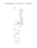
[0054] Taking a close look at FIG. 2, the connector unit 100 includes a clamp 100 installed at the top of the main piston axial 50, and a moving pipe 120, in a belt shape, making the movements following the surface of the piston axial 210 when the main piston axial 50 is making the movements.
[0055] In addition, the connector unit 100 connects between the moving pipe 120 and the clamp 110 and includes a connector section 130 to have the moving pipe 120 making the movements around the surface of the piston 220 when the main piston axial 50 is making the up and down movements.
[0056] The clamp 110 could possibly be made of many different materials in many different shapes expecting to get the solidity in the attachment to the main piston axial 50. An ideal way of putting them together is that the top of the main piston axial 50 is covered by a board shaped metal and then bolts and nuts are installed to possibly strengthen the attachment.
[0057] One end of the connector section 130 is attached to the clamp 100 and the other end of the connector section is attached to moving pipe 120.
[0058] The moving pipe 120 moves around the surface of the piston axial 210 as the clamp 110 makes the up and down movements in cooperation with the movements of the main piston axial 50.
[0059] At this step, the moving pipe 120 is separated from the piston axial 210 and making the up and down movements following the surface generating the pressures onto top and bottom stoppers 230 and 240 have the piston axial 210 making the up and down strokes.
[0060] More detailed discussions will be developed on the movements and the relations between the top and bottom stoppers 230 and 240 installed onto the moving pipe 120 and the piston axial 210.
[0061] On the other hand, the piston unit 200 includes the piston axial 210, making the up and down movements from inside to outside, separated from the main piston axial 50 but connected to the connector unit 100 inside of the cylinder unit 300.
[0062] In addition, the piston unit 200 includes a piston 220, in a rounded board shape, making the up and down movements inside of the cylinder unit 300 at the very bottom of the piston axial 210.
[0063] The piston unit 200 includes the top and bottom stopper 230 and 240, assisting the up and down movements of the piston axial 210 inside of the cylinder unit 300, being forced by the pressures of the connector unit, at both the top and bottom of the piston axial 210.
[0064] Especially, the piston 220 includes a packing 250, attached to inner part of the cylinder unit 300 in covering the surface of the piston 220.
[0065] The piston axial 210, the piston 220, and the top and bottom stoppers 230 and 240 are expected to be made of the FRP (fiber reinforced plastics), lighter than metal materials, and easy to be installed and removed since the high formability and corrosion resistance level.
[0066] In addition, the moving pipe 120 moves up and down without being impeded by any elements around during the movements, as being separated from the surface of the piston axial 210 between the upper and bottom stoppers 230 and 240 as the main piston axial 50 is making the movements.
[0067] Accordingly, the piston axial 210 is only possible to make the up stroke when the moving pipe 120 is attached to the top stopper 230, or to make the down/up stroke when it is attached to the bottom stopper 240.
[0068] In addition, the distance between the top and bottom stoppers 230 and 240, in the piston unit 200, could be different in terms of the types of the installations of the individual users in different needs.
[0069] Furthermore, the cylinder unit 300 performs to create the needed pressures to lift the extracting objects 10 to above ground level as the piston unit 200 makes the up and down movements inside of the piston unit 200.
[0070] The cylinder unit 300 is installed above the Earth's surface, and create the pressures to suck the extracting objects 10 to the ground level, and helping the piston 220 making the movements, in cooperation with the piston axial 210, through the connector unit 100 as the main piston axial 50 is making the repeated up and down movements.
[0071] In this step, the cylinder unit 300 is expected to be supported with other components (not shown) on the Earth's surface 3, and the piston unit 200 is expected to be supported with the cylinder unit 300.
[0072] In addition, the inner part of the cylinder unit 300 is sealed or with no active air flows and this could cause possible difficulties in making the up and down movements of the piston 220. In order to prevent this problem, an airflow control hose 310 is installed and it is connected to the top and bottom of the cylinder unit 300 through the outside of the cylinder unit 300.
[0073] The airflow control hose 310 performs to have the piston 220 possibly making the up and down movements smoothly without the air resistance inside of the cylinder unit 300.
[0074] The airflow control hose 310 is installed to have the air in the upper section of the piston 220 discharged to outside of the cylinder unit 300, when the piston 220 moves up inside of the cylinder unit 300.
[0075] Further, the airflow control hose 310 is installed to have the air, in the bottom of the piston 220, flowing into the upper section of the cylinder unit 300 after flowing out from the bottom of the piston 220, when the piston 220, inside of the cylinder unit 300, moves down.
[0076] On the other hand, the sucking power of the cylinder unit 300 is expected to have the additional amount, created by the sucker rod 1. For this work, the supply unit 400 is installed to connect between the cylinder unit 300 and the main cylinder unit 30.
[0077] In other words, the supply unit 400 performs to have the extracting objects 10 being forced into the storage 9 once they has been lifted to the ground level while the piston unit 200 moves up and down inside the cylinder unit 300.
[0078] Here, the supply unit 400 connects the cylinder unit 300, the main sucking tube 32 of the main cylinder 30, and the main airflow tube 34.
[0079] Accordingly, the pressures, created from the cylinder unit 300, make the additional amount of the objects 10 conveyed into the main cylinder 30 passing through the main sucking tube 32 and the main airflow tube 34.
[0080] For this work, the supply unit 400 has the main sucking tube 32, being connected to the main cylinder 30 and conveying the mining objects 10, being sucked and lifted to the Earth's surface, and a sucking tube 410, which is connected to the cylinder unit 300.
[0081] The supply unit 400 has a main airflow tube 34, connected to the main cylinder 30, performing as a path for the lifted extracting objects 10 to be delivered to the storage 9, and an airflow tube 420, connected to the cylinder unit 300.
[0082] The supply unit 400 further includes a tap 430. The tap 430 is installed inside of the sucking tube 410 and airflow tube 420 against each other in the opposite directions. The tap 320 opens the airflow tube 420, when the sucking tube 410 is closed, and the top closes the airflow tube 420, when the sucking tube 410 is open as the piston unit 200 moves up and down.
[0083] Finally, the supply unit 400 further includes an extra airflow tube 440. The extra airflow tube 440 is installed in order to be connected to the path of the sucking tube 410 and the airflow tube 420 not to be interfered with any of the movements created by the piston unit 200 when the amount of the mining objects 10 lifted is over the volume of the inner part of the cylinder unit 300.
[0084] Accordingly, the sucking tube 410 performs as a path to convey additionally the sucking power of the cylinder unit 300 to the main sucking tube 320, when the mining objects 10 are lifted through the main sucking tube 32 by the sucking power created by the main cylinder 30.
[0085] The airflow tube 420 performs as a path for the extracting objects 10 with airflow power, conveying the objects into the storage 9 passing through the main airflow tube 34, once the objects 10 are forced to the ground level with the airflow power delivered into the main airflow tube 34 from the cylinder unit 300.
[0086] Further, the extra airflow tube 440 performs as a prior path for the extracting objects 10 to be forced into the airflow tube 420, when the objects 10 have been excessively lifted to the ground level and the amounts are more than the capacity level of the cylinder unit 300.
[0087] Here, more detailed description of the tap 430 will be in the followings.
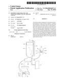
[0088] FIG. 3 is an illustration, a performance example of the productivity increasing equipment with the invention for extracting the crude oil and gas process.
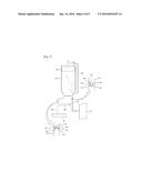
[0089] FIG. 4 is an illustration, another performance example of the productivity increasing equipment with the invention for extracting the crude oil and gas process.
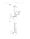
[0090] Referring to FIGS. 3 and 4, associated with FIGS. 1 and 3, FIG. 3 is illustrating the movements of the connector unit 100, the piston unit 200, the cylinder unit 300, and the supply unit 400 when the main piston axial 50 moves down.
[0091] FIG. 4 is illustrating the movements of the connector unit 100, the piston unit 200, the cylinder unit 300, and the supply unit 400 when the main piston axial 50 moves up.
[0092] When the main piston axial 50 moves down inside of the main cylinder 30, the mining objects 10 lifted to the Earth's surface 3 will be forced into the storage 9 passing through the main airflow tube 34 connected to the main cylinder 30 as shown in FIG. 3.
[0093] As described, the connector unit 100 includes the clamp 110, attached to the main piston axial 50, the moving pipeline 120, being separated from the surface of the piston axial 210 and moving around the surface of the piston axial 210, and the connector section 130, connecting between the clamp 110 and the moving pipeline 120 and having the moving pipeline 120 making the movements as the clamp 110 makes the movements.
[0094] The piston unit 200 includes the piston axial 210, moving up and down from inside to outside of the cylinder unit 300, and the piston 220, a rounded board shape and installed at the very bottom of the piston axial 210 moving up and down.
[0095] The piston unit 200 further includes the top and bottom stoppers 230 and 240, installed at both top and bottom of the piston axial 210 and helping the up and down movements of the piston axial 210, inside of the cylinder unit 200, with the pressures of the connector unit 100.
[0096] The supply unit 400 includes the sucking tube 410 and the airflow tube 420.
[0097] The supply unit 400 further includes the tap 430, installed inside of the sucking tube 410 and airflow tube 420 against each other in the opposite directions. The tap 430 opens the airflow tube 420, when the sucking tube 410 is closed, and the top closes the airflow tube 420, when the sucking tube 410 is open as the piston unit 200 moves up and down.
[0098] Further, the supply unit 400 includes the extra airflow tube 440, helping the extracting objects 10 have a prior flow into the airflow tube 420 when they are lifted to above ground to be delivered into the cylinder unit 300.
[0099] As the main piston axial 50 moves down inside of the main cylinder 30, the clamp 110 of the connector unit 100, connected to the main piston axial 50, moves down together.
[0100] Once the clamp 110 moves down, the connector section 130 and moving pipeline 120 also moves down. The moving pipeline 120 makes the movements following the surface of the piston axial 210 and closely positioned to bottom stopper 240, which is formed at the bottom of the piston axial 210.
[0101] As the clamp 110 moves down, the bottom of the moving pipeline 120 presses the upper side of the bottom stopper 240 and the piston 220, placed at the bottom of the piston axial 210, moves down inside of the cylinder unit 300.
[0102] Since the pressures created when the piston 220 moves down inside of the cylinder unit 300, the mining objects 10 are injected into the main airflow tube 34 passing through the airflow tube 420.
[0103] Here, the extracting objects 10, transferred to the main airflow tube 34 through the airflow tube 420, are forced into the storage 9 passing through the main airflow tube 34.
[0104] At that time, the tap 430 in the airflow tube 420 will be open, and the tap 430 in the sucking tube 410 will be closed.
[0105] After the mining objects 10 have been stored in the storage 9, the main piston axial 50 moves up.
[0106] While the piston 220 moves up inside of the cylinder unit 300, the airflow control hose 310 in the cylinder unit 300 is installed to have the air, from the top of the piston 220 inside of the cylinder unit 300, flow out and then flow in again to the cylinder unit 300.
[0107] When the piston 220 in the cylinder unit 300 moves down, the airflow control hose 310 is installed to have the air, at the bottom of the piston 220 inside of the cylinder unit 300, flow out and then flow in again to the cylinder unit 300.
[0108] As shown in FIG. 4, once the main piston axial 50 inside of the main cylinder 30 moves up, the clamp 110 of the connector unit 100, which is connected to the main piston axial 50, also moves up.
[0109] When the clamp 110 moves up, the connector section 130 and the moving pipeline 120 also move up. The moving pipeline 120 moves up following the surface of the piston axial 210 and then closely positioned to the top stopper 230, which is positioned at the top of the piston axial 210.
[0110] Then, as the clamp 110 continues to move up, the top of the moving pipeline 120 presses the bottom of the top stopper 240 and the piston 220 formed at the bottom of the piston axial 210 moves up inside of the cylinder unit 300.
[0111] Due to the pressure, which is created by the upward movement of the piston 220 inside of the cylinder unit 200, the extracting objects 10 are possible to be lifted to above ground and those objects 10 flow through the main sucking tube 32 and are injected into the cylinder unit 300 passing through the sucking tube 410.
[0112] When the amounts of the extracting objects 10, lifted to above ground to be flowing into the cylinder unit 300, are excessive, the objects 10 are introduced into the extra airflow tube 440 in order to be transported to the airflow tube 420 in advance.
[0113] As the piston axial 210 moves up and the mining objects 10 are lifted to above ground, the tap 430 in the airflow tube 420 will be closed and the tap 430 in the sucking tube 410 will be open.
[0114] When the piston axial 210 has moved up by the pressures of the moving pipeline 120 and the main piston axial 50 moves down again, the moving pipeline 120 also moves down again following the surface of the piston axial 210 and presses the bottom stopper 240.
[0115] In consequence, when the main piston axial 50 moves down inside of the main cylinder 30 and the mining objects 10 are transported to the storage 9 passing through the main airflow tube 34, the piston axial 210 also moves down and the mining objects 10 are possibly transported to the storage 9 passing through the airflow tube 420.
[0116] In contrast, when the main piston axial 50 moves up inside of the main cylinder 30 and the extracting objects 10 are lifted above ground through the main sucking tube 32, the piston axial 210 moves up and additional amount of the objects 10 are lifted through the sucking tube 410.
[0117] Accordingly, there is a particular cycle for the piston axial 210 in accordance with the cycle of the main piston axial 50 in making up and down the movements.
[0118] FIG. 5 is an illustration, a core section of the productivity increasing equipment with the invention for mining the crude oil and gas.
[0119] FIG. 6 is an illustration, the object of FIG. 5 with the isometric view.
[0120] FIG. 7 is an illustration, a performance example of the productivity increasing equipment with the invention for mining the crude oil and gas.
[0121] FIG. 8 is an illustration, another performance example of the object of FIG. 7.
[0122] Referring to FIGS. 5-8 with FIGS. 1 and 2, the tap 430 includes a closing section 432 having a half dome shape and an opening section 434 having a triangle shape in a cross-sectional view formed at the bottom of the closing section 432.
[0123] The tap 430 further includes a moving section 436 connecting the closing section 432 and the opening section 434 section. The cross-sectional area of the moving section 436 is smaller than that of the closing section 432 and the opening section 434.
[0124] Here, the tap 430 is installed inside of the sucking tube 410 and the airflow tube 420 respectively. The tap 430 in the airflow tube 420 will be closed when the sucking tube 410 is open. The tap 430 in the airflow tube 420 will be open when the sucking tube 410 is closed.
[0125] When the piston axial 210 moves down, the tap in the sucking tube 420 will be open in order to suck and lift the extracting objects 10 above ground and the tap 430 in the airflow tube 420 will be closed as described.
[0126] In the same way, when the piston axial 210 moves down, the tap 430 in the sucking tube 410 will be closed and the tap 430 in the airflow tube 420 will be open in order to transport the extracting objects 10, which were lifted above ground, to the storage 9.
[0127] FIG. 7 is illustrating the movements of the tap 430 in the sucking tube 410 while the piston axial 210 moves up.
[0128] Referring to FIG. 7, a sucking control section 415 is provided between the closing section 432 and the opening section 434 in the sucking tube 410. The sucking control section 415 has a sucking hole 412, which has a smaller diameter than the opening section 434 and the closing section 432 but has a greater diameter than the moving section 436 in order to have the moving section 436 moves around the sucking hole 412.
[0129] An airflow control section 425 is provided between the closing section 432 and the opening section 434 in the airflow tube 420. The airflow control section 425 has an airflow hole 412, which has a smaller diameter than the opening section 434 and the closing section 432 but has a greater diameter than the moving section 436 in order to have the moving section 436 moves around the airflow hole 422.
[0130] In other words, when the piston axial 210 moves up inside of the cylinder unit 300, the extracting objects 10, which are supposed to be lifted above ground through the main sucking tube 32, will be delivered into the cylinder unit 300 passing through the sucking tube 410.
[0131] When the extracting objects 10 are transported into the sucking tube 410 by the sucking power of the cylinder unit 300, the moving section 436 of the tap 430 in the sucking tube 410 moves up from the sucking hole 412 and the top of the opening section 434 will be closely position to the bottom of the air sucking control section 415.
[0132] Having the triangle shaped cross-sectional area, the opening section 434 can't completely close the sucking hole 412 but possibly have the extracting objects 10 running through the unclosed area of the hole and moving into the cylinder unit 300.
[0133] Here, the tap 430 formed in the airflow tube 420 are position in the opposite direction with the tap 430 formed in the sucking tube 410.
[0134] Accordingly, the tap 430 formed in the airflow tube 420 moves up by the sucking power of the cylinder unit 300. The moving section 436 moves up through the airflow hole 422 and the top of the closing section 432 is attached to the bottom of the airflow control section 425.
[0135] The closing section 432 has a dome shape and a round shaped cross-sectional area. Accordingly, the closing section 432 completely closes the airflow hole 422 and the extracting objects 10, which are supposed to be delivered into the storage 9, will be stayed in the airflow tube 420.
[0136] As the piston axial 210 moves up, the tap 430 formed in the sucking tube 410 will be open and the airflow tube 420 will be completely closed.
[0137] The airflow control hose 310 in the cylinder unit 300 is installed to have the air flow out from the top of the piston 220 in the cylinder unit 300 and then flow into the bottom of the cylinder unit 300 when the piston 220 in the cylinder unit 300 moves up.
[0138] The airflow control hose 310 is installed to have the air flow out from the bottom of the piston 220 in the cylinder unit 300 and then flow into the top of the cylinder unit 300 when the piston 220 in the cylinder unit 300 moves down.
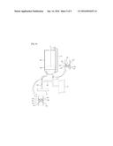
[0139] Alternatively, the movements of the tap 430 formed in the airflow tube 420 are shown in FIG. 8 when the piston axial 210 moves down.
[0140] Referring to FIG. 8, as the piston axial 210 moves down in the cylinder unit 300, the extracting objects 10, which were lifted to the ground through the main sucking tube 32, are delivered into the storage 9 passing through the airflow tube 420 and the main airflow tube 34.
[0141] When the extracting objects 10, which were delivered into the cylinder unit 300 by the airflow power of the cylinder unit 300, are pressed and moved into the airflow tube 420, the moving section 436 of the tap 430 formed in the airflow tube 420 moves down in the airflow hole 422 and the bottom of the opening section 434 will be attached to the top of the airflow control section 425.
[0142] Having the triangle shaped cross-sectional area, the opening section 434 can't completely close the airflow hole 412 but possibly have the extracting objects 10 running through the unclosed area of the hole and moving into the main airflow tube 34.
[0143] Here, the tap 430 formed in the sucking tube 410 are positioned in the opposite direction to the tap 430 formed in the airflow tube 420.
[0144] Accordingly, the tap 430 formed in the sucking tube 410 moves down by the pressure from the cylinder unit 300. The moving section 436 moves down through the sucking hole 412 and the bottom of the closing section 432 is attached to the top of the sucking control section 415.
[0145] The closing section 432 has a dome shape and a round shaped cross-sectional area. Accordingly, the closing section 432 completely closes the sucking hole 412 and securely prevents moving of the extracting objects 10 from the sucking hole 410 to the main sucking hole 32.
[0146] As the piston axial 210 moves up, the tap 430 formed in the sucking tube 410 will be securely closed and the tap 430 formed in the airflow tube 420 will be open. Accordingly, the extracting objects 10 can be transported and stored in the storage 9 through the airflow tube 420 and the main airflow tube 34.
[0147] Having these structures, it will be possible to produce large volume of the crude oil and gas using the sucker rod power for mining the crude oil and gas.
[0148] It will be possible increase productivity by easily installing and removing the sucker rod in the equipment.
[0149] Further, it will be possible to maximize mining efficiency of the crude oil and gas and minimize power consumption of the sucker rod.
[0150] Although the preferred exemplary embodiment of the present invention has been described as above, the present invention is not limited to the aforementioned specific exemplary embodiment. That is, it should be appreciated by those skilled in the art that multiple changes and modifications of the present invention can be made without departing from the spirit and the scope of the appended claims and equivalents to all appropriate changes and modifications are also included in the scope of the present invention.
User Contributions:
Comment about this patent or add new information about this topic:
Images included with this patent application:
 |  |
 |  |
 |  |
| New patent applications in this class: | |
| Date | Title |
|---|---|
| 2019-05-16 | Forged flange lubricator |
| 2016-01-28 | Oil well pump apparatus |
| 2015-03-05 | Control system and apparatus for delivery of a non-aqueous fracturing fluid |
| 2015-01-29 | Crude oil lifting system and method utilizing vane pump for conveying fluid |
| 2015-01-22 | Counterweighted pump jack with reversible motors |
| Top Inventors for class "Wells" | |
| Rank | Inventor's name |
|---|---|
| 1 | Michael L. Fripp |
| 2 | Jean Marc Lopez |
| 3 | Michael H. Johnson |
| 4 | Jørgen Hallundbaek |
| 5 | Dennis P. Nguyen |