Patent application title: TRANSPORTATION OF A DIRECT DRIVE GENERATOR
Inventors:
Uffe Eriksen (Horsens, DK)
Uffe Eriksen (Horsens, DK)
Peder Hykkelbjerg Hansen (Silkeborg, DK)
Henrik Anton Jensen (Ikast, DK)
IPC8 Class: AF03D1100FI
USPC Class:
416244 A
Class name: Fluid reaction surfaces (i.e., impellers) support mounting, carrier or fairing structure turbo machine
Publication date: 2015-12-17
Patent application number: 20150361963
Abstract:
A method of handling a direct drive generator of a wind turbine is
provided. The direct drive generator comprises a stator and a rotor
concentrically arranged about an axis of the direct drive generator. The
method includes steps of placing the direct drive generator on a support
structure, fixing a selected one of the stator or the rotor to the
support structure, connecting actuator means to a remaining one of the
stator or the rotor, and rotating the remaining one of the stators or the
rotor using the actuator means.Claims:
1. A method of handling a direct drive generator of a wind turbine, the
direct drive generator comprising a stator and a rotor concentrically
arranged about an axis of the direct drive generator, wherein the method
comprises: placing the direct drive generator on a support structure;
fixing a selected one of the stator or the rotor to the support
structure; connecting actuator means to a remaining one of the stator or
the rotor; and rotating the remaining one of the stator or the rotor
using the actuator means.
2. The method of the claim 1, wherein the selected one of the stator or the rotor is an inner one of the stator or the rotor and wherein the remaining one of the stator or the rotor is an outer one of the stator or the rotor.
3. The method of claim 1, wherein the selected one of the stator or the rotor is the stator of the direct drive generator and wherein the remaining one of the stator or the rotor is the rotor of the direct drive generator.
4. The method of claim 1, wherein the remaining one of the stator or the rotor is rotated back and forth.
5. The method of claim 1, wherein the step of rotating includes rotating the remaining one of the stator or the rotor during a first time interval and not rotating the remaining one of the stator or the rotor during a second time interval following the first time interval.
6. The method of claim 1, further comprising connecting the actuator means to the support structure.
7. The method of claim 1, further comprising hoisting the support structure with the direct drive generator onto a transportation means.
8. The method of claim 2, wherein the support structure is transported together with the direct drive generator while rotating the inner one of the stator or the rotor.
9. The method of claim 2, wherein the support structure is stored together with the direct drive generator while rotating the inner one of the stator or the rotor.
10. An assembly for handling a direct drive generator of a wind turbine, the direct drive generator comprising a stator and a rotor concentrically arranged about an axis of the direct drive generator, the assembly including a support structure configured to carry the direct drive generator and an actuator means configured to rotate one of the stator or the rotor of the direct drive generator.
11. The assembly of claim 10, wherein the actuator means are connected to the support structure.
12. The assembly of one of the claim 10, wherein the actuator means comprise a hydraulic cylinder.
Description:
CROSS-REFERENCE TO RELATED APPLICATIONS
[0001] This application claims priority to PCT Application No. PCT/EP2013/077872 having a filing date of Dec. 23, 2013, based off of EP 13150378.1 having a filing date of Jan. 7, 2013, the entire contents of which are hereby incorporated by reference.
FIELD OF TECHNOLOGY
[0002] The following relates to a method of handling a direct drive generator of a wind turbine and an assembly for handling a direct drive generator of a wind turbine.
BACKGROUND
[0003] With the increasing demand for renewable energies the typical rated output powers of wind turbines have been growing for many years. The greater output power leads to corresponding increases in the size and weight of the various parts of the wind turbines. Thus, transportation of the parts of the wind turbines has become increasingly difficult. It has been found that rotatable parts of the wind turbines such as bearing may be damaged during transport or storage because of the enormous weight of the individual components. The damage typically shows as stand still marks where the weight of one component causes deformations to itself or an underlying part. One such part of a wind turbine that may be difficult to handle is a direct drive generator.
SUMMARY
[0004] An aspect relates to a method of handling a direct drive generator of a wind turbine. The direct drive generator comprises a stator and a rotor concentrically arranged about an axis of the direct drive generator. The method includes steps of:
[0005] placing the direct drive generator on a support structure;
[0006] fixing a selected one of the stator or the rotor to the support structure;
[0007] connecting actuator means to a remaining one of the stator or the rotor; and
[0008] rotating the remaining one of the stator or the rotor using the actuator means.
[0009] Embodiments of the invention avoid stand still marks by constantly moving or rotating the inner part of the direct drive generator during handling. It should be noted that "rotating" does not necessarily mean rotating the inner part of the direct drive generator by one or more complete revolutions but also motions over only a segment of a circle, e.g. forth and back movements. For example, the outer part of the direct drive generator may rest on the support structure and thereby effectively shields the inner part from any contact with the support structure which may cause damages to the inner part. In this case, the inner part of the direct drive generator will be rotated during handling. Furthermore, since the outer part of the direct drive generator does not move relative to the support structure, the outer part will not be damaged either. Thus, the inventive method protects the direct drive generator against damages from stand still marks and from impacts during handling. In addition, health and safety risks are eliminated by rotating the inner one of the stator or the rotor because the rotating parts are embedded by the outer one of the stator or the rotor which is fixed to the support structure.
[0010] However, in another preferred embodiment of the method of the invention, inner one of the rotor or the stator is fixed to the support structure while the outer one of the rotor or the stator is rotated during handling. The inner one of the rotor or the stator may be fixed to the support structure by means of a flange or the like that is accessible from the outside of the direct drive generator. The inner one of the rotor or the stator may be propped holding the direct drive generator in such a way that the outer one of the rotor or the stator may be rotated without the support structure interfering. Rotating the outer one is especially useful if the outer one is the rotor of the direct drive generator and the inner one is the stator because the rotor is designed for rotating while the stator may comprise ports or connectors for lubricants for a bearing of the direct drive generator which may be connected to a lubricant reservoir and/or pump included in the support structure. Furthermore, rotating the outer one (e.g. rotor of the direct drive generator) is especially useful when the direct drive generator is already installed within a nacelle of a wind turbine and the direct drive generator and the nacelle are handled together. The nacelle effectively shields the rotor which means that the rotor cannot be damaged or cause damage or harm when rotating during handling.
[0011] Preferably, selected one of the stator or the rotor is the stator of the direct drive generator and the remaining one of the stator or the rotor is the rotor of the direct drive generator. The advantage is that the rotor of the direct drive generator is designed for rotation anyway and, as already mentioned above, the stator may comprise ports and connectors that may be connected to suitable means in the support structure used during handling. Furthermore, the direct drive generator may be handled together with a hub connected to it. In such a case the step of connecting actuator means to the rotor can be carried out by connecting the actuator means to the hub in such a way that the rotor will be rotated by means of rotating the hub.
[0012] Preferably, the remaining one of the stator or the rotor is rotated back and forth. As already explained above, such smaller movements are sufficient for avoiding stand still marks. However, rotating the remaining part of the direct drive generator back and forth can be accomplished by less complex means such as a hydraulic cylinder which can expand and contract. The linear motion of the hydraulic cylinder will then be transformed into a rotational movement by the inner part of the direct drive generator. Furthermore, only a relatively small extension and contraction of the actuator means/hydraulic cylinder will be required for a back and forth motion as compared to rotating the remaining one by a plurality of full rotations during handling.
[0013] The step of rotating may include rotating the remaining one of the stator or the rotor during a first time interval and not rotating the remaining one of the stator or the rotor during a second time interval following the first time interval. This procedure can be repeated such that the remaining one of the stator or the rotor is periodically moved thus avoiding stand still marks, for example, the remaining one of the stator or the rotor can be rotated for some seconds every ten minutes thus reducing power consumption. The length of the time intervals can be chosen depending on the situation. For example, the rotation can be constantly carried out during e.g. transportation by train while it may be carried out in intervals while being transported on a truck. Furthermore, the length of the time intervals can be chosen depending on the availability of an external power supply for the actuator means, i.e. rotation may be carried out constantly or with relatively shorter pauses when such a power supply is available and with relatively longer pauses when such a power supply is unavailable.
[0014] The method may further comprise connecting the actuator means to the support structure. The connection to the support structure provides a pivotal point for the actuator means.
[0015] The method may further comprise hoisting the support structure with the direct drive generator onto transportation means. The support structure may then be transported together with the direct drive generator while rotating the inner one of the stator or the rotor. Alternatively, the support structure may be stored together with the direct drive generator while rotating the inner one of the stator or the rotor. Transportation and storing are the most relevant ways of handling the direct drive generator.
[0016] A second aspect of the invention relates to an assembly for handling a direct drive generator of a wind turbine. The direct drive generator comprises a stator and a rotor concentrically arranged about an axis of the direct drive generator. The assembly includes a support structure adapted to carry the direct drive generator and actuator means adapted to rotate one of the stator or the rotor of the direct drive generator.
[0017] In a preferred embodiment of the invention, the actuator means are connected to the support structure. Preferably the actuator means comprise a hydraulic cylinder.
BRIEF DESCRIPTION
[0018] Some of the embodiments will be described in detail, with reference to the following figures, wherein like designations denote like members, wherein:
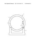
[0019] FIG. 1 shows a direct drive generator arranged on a support structure according to a first embodiment.
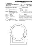
[0020] FIG. 2 shows a direct drive generator installed within a nacelle arranged on a support structure according to a second embodiment.
DETAILED DESCRIPTION
[0021] FIG. 1 shows a direct drive generator 1 arranged on a support structure 4. An outer rotor 3 of the direct drive generator 1 is fixed to the support structure 4 for handling. Thus, the outer rotor 3 cannot move relatively to the support structure 4 thereby avoiding damages to the outer rotor 3 such as scratch marks. Actuator means 5, e.g. a hydraulic cylinder, are connected to an inner stator 2 of the direct drive generator 1. The actuator means 5 of the embodiment shown in FIG. 1 could also be connected to the outer rotor 3 instead of the support structure 4, however, connection of the actuator means 5 to the support structure 4 is preferred because the support structure 4 provides more space for suitable connection means than the relatively thin rim of the outer rotor 3. The actuator means 5 rotate the inner stator 2 relatively to the outer rotor 3 to avoid the generation of stand still marks. The invention may be equally used for direct drive generators having an outer stator and an inner rotor. In this case a first end of the actuator means 5 will connect to the inner rotor and a second end of the actuator means 5 will connect to the outer stator or the support means 4.
[0022] FIG. 2 shows a direct drive generator 1 installed within a nacelle 6 arranged on a support structure 4 which are handled according to a second embodiment of the method of the invention. Here the actuator means 5 are connected to the outer rotor 3 of the direct drive generator 1. The inner stator 2 may be fixed to the support structure 4. For example, the inner stator 2 may be fastened to the support structure 4 by means of nuts and bolts that extend through corresponding borings in the support structure 4 and a flange of the inner stator 2. The nacelle 6 may rest on the support structure 4 or may be affixed to it.
[0023] The invention has an advantage that handling of the direct drive generator 1 e.g. for storing or transportation does not cause any damages to the direct drive generator 1.
[0024] The present invention has been described with respect to exemplary embodiments thereof which serve as illustrative examples of the invention. However, although specific embodiments have been described to explain the invention, deviations from these embodiments are possible. Hence, the scope of the invention shall not be limited by the described exemplary embodiments but only by the appended claims.
User Contributions:
Comment about this patent or add new information about this topic:
Images included with this patent application:
 |  |
 |
| Similar patent applications: | |
| Date | Title |
|---|---|
| 2013-01-31 | Magnetic active flap |
| New patent applications in this class: | |
| Date | Title |
|---|---|
| 2018-01-25 | Closing assembly for closing a blade ring, associated blade supports, turbomachine, and method for inserting a closing assembly |
| 2016-07-14 | Turbine rotor material for geothermal power generation and method for producing the same |
| 2016-07-07 | Flare-type tensile legs floating wind turbine base, offshore wind turbine and construction method |
| 2016-07-07 | Seal and clip-on damper system and device |
| 2016-06-02 | Wind turbine having a reduced radar cross section |
| New patent applications from these inventors: | |
| Date | Title |
|---|---|
| 2016-03-24 | Cooling system |
| 2015-12-10 | Bearing insulation |
| 2015-10-29 | Apparatus for dampening of acoustic noise generated by air-cooling of at least one wind turbine component provided with the nacelle of a wind turbine |
| 2015-01-22 | Bearing for a wind turbine |
| 2014-11-27 | Airflow control arrangement |
| Top Inventors for class "Fluid reaction surfaces (i.e., impellers)" | |
| Rank | Inventor's name |
|---|---|
| 1 | Frank B. Stamps |
| 2 | Ching-Pang Lee |
| 3 | Gabriel L. Suciu |
| 4 | Stefan Herr |
| 5 | Tracy A. Propheter-Hinckley |