Patent application title: CORNER FITTING FOR BOX-LIKE STRUCTURES ON TRANSPORT PALLETS
Inventors:
Helmut Gebetsroither (Scharnstein, AT)
IPC8 Class: AB65D1944FI
USPC Class:
206386
Class name: Special receptacle or package with pallet feature
Publication date: 2015-10-29
Patent application number: 20150307229
Abstract:
A corner fitting for box-like structures on transport pallets, which
fitting connects two respective side wall elements of stackable side wall
frames for the box-like structure using an articulated connection along
an articulation axis and has an aligning element for aligning the side
wall frame relative to the transport pallet or to another adjacent side
wall frame. The aligning element is embodied in the form of a locking
element, which can be moved perpendicular to the articulation axis
between a locking position and a release position and is situated in a
first end region of the articulated connection, and a receiving pocket
with a locking opening for the locking element of another corner fitting
is provided in the opposite, second end region of the articulated
connection. With the aid of the invention, a corner fitting is
implemented which allows an easy reciprocal alignment of side wall frames
and transport pallets and facilitates repeated assembly of box-like
structures on transport pallets, as well as the loading thereof.Claims:
1. A corner fitting for box-like structures on transport pallets, which
fitting connects two respective side wall elements of stackable side wall
frames for the box-like structure using an articulated connection along
an articulation axis, the fitting comprising: an aligning element for
aligning the side wall frame relative to the transport pallet or to
another adjacent side wall frame, wherein the aligning element is a
locking element, which can be moved perpendicular to the articulation
axis between a locking position and a release position and is situated in
a first end region of the articulated connection, and a receiving pocket
with a locking opening for the locking element of another corner fitting
is provided in an opposite, second end region of the articulated
connection.
2. The corner fitting according to claim 1, wherein the locking element is a locking bolt that is guided in a housing and is prestressed perpendicular to the articulation axis.
3. The corner fitting according to claim 1, further comprising a removable cover plate, which has a conical projection protruding parallel to the articulation axis.
4. A side wall frame comprising a corner fitting according to claim 1.
Description:
FIELD OF THE INVENTION
[0001] The invention relates to a corner fitting for box-like structures on transport pallets, which fitting connects two respective side wall elements of stackable side wall frames for the box-like structure by means of an articulated connection along an articulation axis and has an aligning element for aligning the side wall frame relative to the transport pallet or to another adjacent side wall frame.
BACKGROUND OF THE INVENTION
[0002] Transport pallets are used for conveying larger goods and are usually made of wood. They are also referred to as "Euro pallets" or as "Europool pallets" and are composed of bottom boards and top boards, which are connected to one another by means of blocks positioned between them. An open space remains between the bottom boards and top boards, into which the blades of a floor conveyor unit, fork lift truck, or lift truck can be inserted in order to then be able to move the transport pallets for short distances, for example to load them onto a truck or railcar.
[0003] To transport loose goods, bulk goods, or delicate goods, side wall elements are placed onto the transport pallets to create box-like structures, which are bounded at the bottom by the top boards of the transport pallet and at the top by the bottom boards of another transport pallet possibly stacked on top. For this purpose, the side wall elements are connected to one another by means of corner fittings, usually in pivoting fashion in order to permit them to be folded up and stored in a space-saving way when they are not needed. Each set of four side wall elements forms a side all frame that is closed in the circumference region, onto which other side wall frames can be stacked until the box-like structure has reached a desired height and is closed at the top by another transport pallet. Other side wall frames can then be placed onto this top transport pallet.
[0004] When they are stacked, the side wall frames must be aligned relative to one another and also relative to the transport pallet. Conventional corner fittings have aligning elements for this purpose in the form of outer aligning lugs, which protrude downward, parallel to the articulation axis. In the use position, these aligning lugs rest snugly against the outer surfaces that converge in the corner region of the underlying transport pallet or the underlying side wall frame.
[0005] Aligning lugs of the conventional kind are in fact simple in design and widely used, but they have several disadvantages in practice. They protrude slightly beyond the outer surface of the transport pallet and the side wall elements and are thus in practice subject to significant stress. Transport pallets must be densely loaded when transported, not only for reasons of optimal space utilization, but also for reasons of load safety. For this reason, aligning lugs often catch on other parts or other aligning lugs and end up getting bent. These bent aligning lugs complicate subsequent handling of the transport pallets and often result in damage to other parts. Bent aligning lugs must then be bent back into position, which is labor-intensive and delays the overall loading process.
[0006] In addition, conventional aligning elements do not provide a tensile connection, making it necessary to then place a strap clamp around a stack of transport pallets and side wall frames in order to prevent vertical movements during transport. These strap clamps are usually made of plastic and are cut off and discarded after use. Consequently, they not only take up a large amount of time for the clamping, but also generate a large amount of waste.
[0007] The object of the invention, therefore, is to avoid these disadvantages and to create a corner fitting that permits a simple reciprocal alignment of side wall frames and transport pallets and that facilitates repeated assembly of box-like structures on transport pallets as well as the loading thereof.
SUMMARY OF THE INVENTION
[0008] These objects are attained by a corner fitting for box-like structures on transport pallets, which fitting connects two respective side wall elements of stackable side wall frames for the box-like structure by means of an articulated connection along an articulation axis and has an aligning element for aligning the side wall frame relative to the transport pallet or to another adjacent side wall frame. According to the invention, the aligning element is embodied in the form of a locking element, which can be moved perpendicular to the articulation axis between a locking position and a release position and is situated in a first end region of the articulated connection, and a receiving pocket with a locking opening for the locking element of another corner fitting is provided in the opposite, second end region of the articulated connection. The locking in this case is produced between two corner fittings situated one on top of the other or between a corner fitting and the transport pallet, as will be explained in greater detail below. Since the aligning element provided according to the invention is able to move perpendicular to the articulation axis between a locking position and a release position, when stresses occur in the direction of the articulation axis and therefore in the direction of the edge of the corner of the side wall frame, the locking exerts a movement-inhibiting action and thus represents a tensile connection. Strap clamps and the like for vertical fixing are therefore no longer necessary. It is also possible to avoid having parts that protrude beyond the outer surfaces of the side wall frames and the transport pallet.
[0009] The locking element can for example be embodied in the form of a locking bolt that is guided in a housing and is prestressed perpendicular to the articulation axis.
[0010] As has already been mentioned, the box-like structure can be closed at the top by another transport pallet. In order to ensure an alignment relative to this transport pallet as well, it is also proposed that a cover plate be provided, which has a conical projection protruding parallel to the articulation axis. This projection can engage in a corresponding conical recess in the bottom boards of the overlying transport pallet so as to ensure a relative alignment.
BRIEF DESCRIPTION OF THE DRAWINGS
[0011] The invention will be explained in greater detail below through exemplary embodiments taken in conjunction with the accompanying figures. In the drawings:
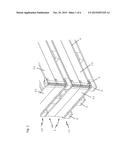
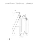
[0012] FIG. 1 shows an arrangement of two transport pallets, each with two side wall frames stacked on it with a corner fitting according to the invention,
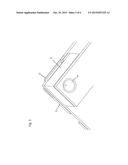
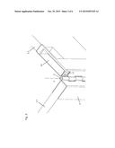
[0013] FIG. 2 shows a perspective detail view of an embodiment of a locking element according to the invention,
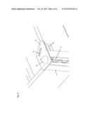
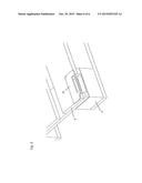
[0014] FIG. 3 shows a perspective detail view of an embodiment of a receiving pocket according to the invention for the locking element,
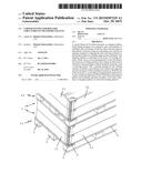
[0015] FIG. 4 shows a perspective detail view of an embodiment of a cover plate,
[0016] FIG. 5 shows a perspective detail view of an embodiment of a conical recess for receiving the conical projection of the cover plate, and
[0017] FIG. 6 shows a perspective detail view of an embodiment of a locking plate that permits a transport pallet to receive the locking element.
DETAILED DESCRIPTION OF THE PREFERRED EMBODIMENTS
[0018] First, we refer to FIG. 1, which shows an arrangement of two transport pallets 1, each with two side wall frames 2 stacked on it with a corner fitting 5 according to the invention. The transport pallets 1 are composed of bottom boards and top boards 4, which are connected to one another via blocks 3 that are positioned between them. A side wall frame 2 is composed of four side wall elements 2.1, 2.2, 2.3, 2.4, of which only two side wall elements 2.1, 2.2 are visible in FIG. 1. The four side wall elements 2.1, 2.2, 2.3, 2.4 of a side wall frame 2 are connected to one another in articulating fashion by means of four corner fittings 5.1, 5.2, 5.3, 5,4. Each side wall frame 2 is open at the top and bottom--it being possible to stack a plurality of side wall frames 2 on top of one another--and in this case is bounded below by a lower transport pallet 1.1 and above by an upper transport pallet 1.2. FIG. 1 also shows that the corner fittings 5 do not have any parts that protrude beyond the outer surface of the transport pallets 1 and the side wall elements 2. This situation is made possible by the embodiment of the corner fittings 5 according to the invention, which will be explained below in conjunction with FIGS. 2 and 3.
[0019] FIG. 2 shows a perspective detail view of an embodiment of a locking element 6 according to the invention, which is supported in sliding fashion inside a housing 7. The housing 7 is in turn fastened to a housing holder 8, which is formed onto the corner fitting 5 or fastened to the side wall element 2.2. FIG. 2 also shows an articulated connection 9 of the corner fitting 5, which defines an articulation axis A, which is more clearly shown in FIG. 3. The locking element 6 is embodied in the form of a locking bolt that is guided inside the housing 7 and is prestressed perpendicular to the articulation axis A and can be moved perpendicular to the articulation axis A between a locking position and a release position.
[0020] The locking element 6 is situated in a first end region of the articulated connection 9, i.e. the lower end region in the example shown in FIGS. 2 and 3, and engages in a receiving pocket 10 of another corner fitting 5 (see FIG. 3), which is situated in the opposite, second end region of the articulated connection 9. A corner fitting 5 consequently has a locking element 6 in a first end region of the articulated connection 9 and a receiving pocket 10 situated in its opposite, second end region of the articulated connection 9, with the locking element 6 of a first corner fitting 5 engaging in the receiving pocket 10 of another corner fitting 5 resting against it. As it enters into the receiving pocket 10, the locking bolt is first pushed back and then protrudes through a locking opening 11 of the receiving pocket 10. The position of the locking element 6 in which it is retracted into the housing 7 will be referred to below as the release position and the position in which the locking element 6 protrudes through the locking opening 11 of the receiving pocket 10 will be referred to as the locking position. The receiving pocket 10 can for example be formed into the corner fitting 5 or can be produced by means of a cutout in the side wall element 2.2.
[0021] The box-like structure can be closed at the top by another transport pallet 1.2. In order to ensure an alignment relative to this transport pallet 1.2 as well, a cover plate 12 is provided, which has a conical projection 13 protruding parallel to the articulation axis A, as shown in FIG. 4. This projection 13 engages in a corresponding conical recess 14 (see FIG. 5), which is situated in a bottom board of the overlying transport pallet 1.2 so that a relative alignment is ensured.
[0022] The box-like structure can also be closed at the bottom by a transport pallet 1.1. In order to ensure an alignment relative to this transport pallet 1.1 as well, a locking plate 15 is provided, which is situated in a top board 4 of the underlying transport pallet 1.1, as shown in FIG. 6. The locking plate 15 here covers a corresponding cutout in the top board 4 of the transport pallet 1.1 and can be engaged from behind by the locking element 6. The locking plate 15 and the cutout in the top board 4 consequently comprise a recess for the locking element 6 that is analogous to the above-described receiving pockets 10.
[0023] The locking with the aid of the locking elements 6 engaging in the receiving pockets 10 is therefore produced between two corner fittings 5 that are stacked on top of each other. The locking with the aid of the locking elements 6 engaging in the locking plates 15, however, is produced between a corner fining 5 and the underlying transport pallet 1.1. Since the aligning element provided according to the invention can be moved perpendicular to the articulation axis A between a locking position and a release position, the locking exerts a movement-inhibiting action when stresses occur in the direction of the articulation axis A and therefore in the direction of the edge of the corner of the side wall frame 2 and thus represents a tensile connection. Strap clamps and the like for vertical fixing are therefore no longer necessary, but the top cover plates 12 on which no additional transport pallet 1 is placed can be clamped diagonally with strap clamps, for which purpose oblong holes 16 are provided in the cover plates 12.
[0024] With the aid of the invention, a corner fitting 5 is implemented which allows an easy reciprocal alignment of side wall frames 2 and transport pallets 1 and facilitates repeated assembly of box-like structures on transport pallets 1 as well as the loading thereof.
User Contributions:
Comment about this patent or add new information about this topic:
Images included with this patent application:
 |  |
 |  |
 |  |
 |
| Similar patent applications: | |
| Date | Title |
|---|---|
| 2016-01-07 | Covering, protecting, and positioning a portable electronic device |
| 2015-11-19 | Food container with forced moisture removal |
| 2015-12-10 | Container having excellent slipping property for fluid contents |
| 2015-12-10 | Container system for releasably storing a substance |
| 2016-01-07 | Method and system for using an inner pack frame to contain loose elongated smoking articles in a hinge lid pack |
| New patent applications in this class: | |
| Date | Title |
|---|---|
| 2022-05-05 | Pallet and container kit |
| 2016-12-29 | Stackable pallet container fitted with a top reinforcement frame |
| 2016-09-01 | Portable silo assembly |
| 2016-09-01 | Pallet assembly and a lid apparatus for the pallet assembly |
| 2016-07-07 | Sleeve pack assembly |
| Top Inventors for class "Special receptacle or package" | |
| Rank | Inventor's name |
|---|---|
| 1 | Donald E. Weder |
| 2 | Brett R. Glass |
| 3 | Daniel Lee Bizzell |
| 4 | Andrea Biondi |
| 5 | Nicole E. Glass |