Patent application title: Prosthetic System
Inventors:
Ryan Hawkins (Sallisaw, OK, US)
IPC8 Class: AA61F268FI
USPC Class:
623 26
Class name: Prosthesis (i.e., artificial body members), parts thereof, or aids and accessories therefor having fluid actuator
Publication date: 2015-10-29
Patent application number: 20150305896
Abstract:
A prosthetic device having a housing, an axle, at least three housing
vanes, a flow medium and a valve. The axle is disposed within the housing
and moveable independently of the housing. The axle has an axle reservoir
and at least three axle vanes extending from the axle to contact the
chamber wall. The three housing vanes extend from a chamber wall and
contact the axle. A first opening and a second opening are formed in each
axle vane. The flow medium is contained entirely within the chamber and
the axle reservoir. The valve is disposed in the axle and operable in
response to movement of the axle in a first direction relative to the
housing to allow the flow medium to enter the axle reservoir from the
chamber for storage under pressure.Claims:
1. An apparatus for controlling movement of a prosthetic device, the
apparatus comprising: a housing comprising a first chamber; a storage
chamber; a first member connected to the housing; an axle moveable
independently of the housing; wherein the housing and axle are moveable
relative to each other between a first position and a second position by
placing an external force on the first member; a flow medium disposed
within the first chamber and movable from the first chamber to the
storage chamber for storage under pressure in response to movement of the
housing in a first direction to the second position and to control
movement of the flow medium from the storage chamber to first chamber
when the external force is altered.
2. The apparatus of claim 1 wherein the housing further comprises a second chamber, and wherein the flow medium is also disposed within the second chamber when the housing is in a first position.
3. The apparatus of claim 1 wherein the first chamber is defined by a housing vane extending from the housing to contact the axle.
4. The apparatus of claim 3 further comprising an axle vane extending from the axle to contact a housing wall.
5. The apparatus of claim 1 wherein the axle comprises an axle chamber and comprising a valve disposed in the axle and moveable to regulate movement of the flow medium between the first chamber and the storage chamber.
6. The apparatus of claim 1 wherein the axle comprises a pressurized axle chamber and an axle storage chamber, wherein the pressurized axle chamber is fluidly connected to the storage chamber, and wherein the pressurized flow medium chamber and the axle storage chamber are separated by a central body of the axle.
7. The apparatus of claim 6 wherein flow medium overflows from the storage chamber to the pressurized axle chamber when the amount of flow medium in the storage chamber exceeds a storage chamber capacity.
8. The apparatus of claim 7 wherein the pressurized axle chamber comprises a movable partition to divide the pressurized chamber into sub-chambers, wherein a first pressurized sub-chamber contains a variable amount of flow medium and a second sub-chamber contains a fluid, wherein the fluid biases the partition toward the central body to compress the first pressurized sub-chamber and wherein the axle storage chamber comprises a movable partition to divide the axle storage chamber into an overflow chamber and an air chamber.
9. The apparatus of claim 8 wherein the axle comprises a valve fluidly connected to the second sub-chamber and allows for the movement of fluid into the second sub-chamber to increase a fluid pressure therein.
10. The apparatus of claim 1 further comprising a second member connected to the axle.
11. The apparatus of claim 1 wherein the axle comprises a first end and a second end, wherein a first splined end cap is connected to the axle at the first end and a second splined end cap is connected to the axle at the second end, wherein the first splined end cap operatively engages a first internally splined portion of the second member and the second splined end cap operatively engages a second internally splined portion of the second member.
12. The apparatus of claim 10 wherein the second member comprises a limb connector.
13. The apparatus of claim 12 wherein the first member comprises a prosthetic foot.
14. A method for controlling movement of a prosthetic device, the method comprising: providing a prosthetic joint having a housing and an axle moveable independently of the housing, wherein one of the housing or axle is connected to a first member and the other connected to a second member; placing an external force on the first member to move the housing from a first position to a second position relative to the axle; moving a flow medium from a first chamber to a second chamber for storage under pressure in response to movement of the housing in a first direction; and altering the external force on the first member to move the flow medium from the second chamber and control movement of the housing.
15. The method of claim 14 wherein the housing is connected to the first member comprising a prosthetic foot, and wherein placing an external force on the first member comprises contacting a heel of the prosthetic foot to a surface.
16. The method of claim 15 wherein altering the external force from the first member comprises removing the heel from the surface.
17. A device having an articulating joint, the device comprising: a housing; an axle disposed within the housing configured to act as the articulating joint and moveable independently of the housing; a housing vane extending from the housing toward the axle; an axle vane extending from the axle toward the housing; wherein the axle vane and the housing vane define a first chamber and a second chamber; and a flow medium contained within the housing to flow between the first chamber and the second chamber in response to movement of the housing relative to the axle.
18. The device of claim 18 further comprising an axle chamber disposed in the axle, wherein the flow medium is contained within the housing and the axle and flowable between the housing and the axle chamber in response to movement of the housing relative to the axle.
19. The device of claim 18 further comprising a valve disposed in the axle to regulate flow of the flow medium between the housing and the axle chamber in response to movement of the axle relative to the housing.
20. The device of claim 18 wherein the axle vane comprises an opening, wherein the flow medium communicates between the housing and the axle chamber through the opening in the axle vane.
Description:
CROSS REFERENCE TO RELATED APPLICATION
[0001] This application is a continuation of U.S. Ser. No. 13/532,565 filed Jun. 25, 2012, now U.S. Pat. No. 9,072,615, which is a continuation of U.S. Ser. No. 12/695,233, filed on Jan. 28, 2010, now U.S. Pat. No. 8,206,458, the entire contents of which are incorporated herein by reference.
FIELD
[0002] The present invention refers to a prosthesis system used in a prosthetic limb and more specifically to a hydraulically drive prosthetic joint.
SUMMARY
[0003] The present invention is directed to an apparatus for controlling movement of a prosthetic device. The apparatus comprises a housing comprising a first chamber, a storage chamber, a first member connected to the housing, and an axle moveable independently of the housing. The housing and axle are moveable relative to each other between a first position and a second position by placing an external force on the first member. A flow medium is disposed within the first chamber and movable from the first chamber to the storage chamber for storage under pressure in response to movement of the housing in a first direction to the second position and to control movement of the flow medium from the storage chamber to first chamber when the external force is altered.
[0004] The present invention is also directed to a method for controlling movement of a prosthetic device. The method comprises providing a prosthetic joint having a housing and an axle moveable independently of the housing, wherein one of the housing or axle is connected to a first member and the other connected to a second member. An external force is placed on the first member to move the housing from a first position to a second position relative to the axle. A flow medium is moved from a first chamber to a second chamber for storage under pressure in response to movement of the housing in a first direction. The external force on the first member is altered to move the flow medium from the second chamber and control movement of the housing.
[0005] Further still, the present invention is directed to a device having an articulating joint. The device comprises a housing, an axle, a housing vane, and a flow medium. The axle is disposed within the housing and configured to act as the articulating joint and moveable independently of the housing. The housing vane extends from the housing toward the axle. The axle vane extends from the axle toward the housing. The axle vane and the housing vane define a first chamber and a second chamber. The flow medium is contained within the housing to flow between the first chamber and the second chamber in response to movement of the housing relative to the axle.
BRIEF DESCRIPTION OF THE FIGURES
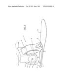
[0006] FIG. 1 is a perspective view of a prosthetic device joint in accordance with the present invention. The joint of FIG. 1 is shown used as an ankle joint in a prosthetic foot.
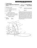
[0007] FIG. 2 is a partial cut-away view of the prosthetic joint of FIG. 1 showing the housing chamber, axle vanes and housing vanes.
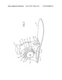
[0008] FIG. 3 is a side view of the prosthetic joint of the present invention showing a plurality of channels connecting the chamber to an axle reservoir.
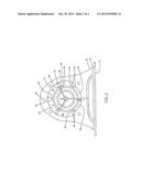
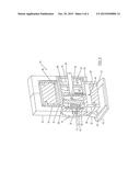
[0009] FIG. 4 is a perspective view of a cross-section of the joint of the present invention.
DETAILED DESCRIPTION
[0010] Prosthetic devices provide a valuable service for amputees and provide an enhanced quality of life amputees would otherwise not enjoy. Currently, research in prosthetic devices is focused on providing natural movement and control of a prosthetic device. Devices and systems have been developed to enhance movement of prosthetic joints. However, there remains a need to improved devices that enable controlled movement of prosthetics limbs.
[0011] Turning now to the Figures and specifically to FIG. 1, there is shown therein a prosthetic device 10 of the present invention. The prosthetic device 10 comprises a housing 12, an axle 14, a prosthetic foot 16, and a limb connector 18 attached to the axle, A platform 20 is connected to a plurality of housing feet 22 which is then connected to the prosthetic foot 16. The platform 20 provides structural support for the housing 12. One skilled in the art will appreciate that the exterior of the housing 12 may be configured differently for different and varied applications without departing from the spirit of the present invention. A cover 24 is connected to a housing body 26 using a fastener (not shown) secured in holes 28.
[0012] The axle 14 is splined to engage a matingly splined portion of the limb connector. The axle 14 is shown with an as yet to be described valve stem 30. The splined connected between the limb connector 18 and axle 14 allows for movement of the limb connector and axle together. Movement of the limb connector 18 and axle 14 is independent of the housing 12 and prosthetic foot 16.
[0013] Turning now to FIG. 2, there is shown therein the prosthetic device 10 of FIG. 1 in a partially cut-away view. The device 10 of FIG. 2 shows the prosthetic foot 16 connected to the platform 20. As discussed above, the platform 20 is connected to the housing feet 22 for movement therewith. The housing 12 is shown with the housing cover 24 removed from one side of the housing to show a chamber 32 having a chamber wall 34. A plurality of housing vanes 36 extend from the chamber wall 34 to contact the axle 14. The housing vanes 36 define a plurality of housing reservoirs within the chamber 32.
[0014] The axle 14 is disposed within the housing and extends beyond either side of the housing 12 and housing covers 24. The axle 14 is configured to act as an articulating joint for the prosthetic device and is moveable independently of the housing 12. The portion of the axle 14 extending outside the housing 12 may comprise splines formed to matingly engage similarly form splines of the limb connector 18. A plurality of axle vanes 38 extend from the axle 14 to contact the chamber wall 34. A select axle vane 38 is moveable within its housing reservoir n response to movement of a flow medium (not shown) or of the limb connector 18 and axle 14 relative to the housing 12.
[0015] Turning to FIG. 3, each axle vane 38 has a first opening 40 formed in the axle vane. Each axle vane 38 comprises a notch 33 formed to hold a vane seal (not shown) to hermetically seal housing reservoirs 32, 42, and 44. A second opening 46 is formed in each axle vane 38 is positioned opposite the first opening 40. Upon movement of the axle 14 in direction A the flow medium is forced into openings 40 from reservoirs 32 and 42 and into passage way 48. The flow medium travels through passage 48 and into reservoir 44 where it is stored for later use. Excess flow medium may be stored in an axle reservoir, to be discussed later herein. A sensor (not shown) in reservoir 44 controls a valve (FIG. 4) and directs the flow medium into either the reservoir 44 or the axle reservoir (FIG. 4) depending on the pressure reading. The movement of the axle vanes 38 in direction A creates a vacuum in reservoirs 32, 42 and 45. The vacuum and pressurized fluid in reservoir 44 causes the axle to move in direction B to reset the axle relative to the housing when the foot is lifted from the ground. Alternatively, the flow medium may move through the first opening and out of the second opening 46 into reservoirs 32 and 42.
[0016] Reservoirs 44 and 45 are generally smaller than reservoirs 32 and 42. During the heel strike portion of an individual's gait the flow medium moves from reservoirs 32 and 42 into the central reservoir. The central valve regulates the flow of the medium from the housing reservoirs 42 and 32 to the central reservoir to make efficient use of the volumetric efficiency of the larger reservoirs 42 and 32 versus the smaller reservoirs 44 and 45 when the individual lifts the foot and needs to reposition it. The flow medium is routed from the central reservoir to the smaller reservoir 44 and 45.
[0017] Continuing with FIG. 3, a sensor 49 is supported by the housing 12 to detect an angular position between the housing and the axle. In a preferred embodiment six sensors 49 are disposed about the housing to detect an angular position between the axle and the housing. Sensors 49 may comprise pressure sensors to detect pressure changes in the flow medium disposed in a corresponding chamber. The pressure data from each sensor may be multiplied by the area presented perpendicularly to an axis of rotation as well as the distance from a center of rotation to the center of the area to calculate the torque applied by each side of a vane member 46. The cumulative torque data may be transmitted to a processor (not shown) that uses the data to alter the torque by means of an optional proportional flow valve (not shown) disposed in the axle in combination with selection of the active vane areas. The data used by the processor may be derived from the angular position sensor by means of a control law such as a state space ND control loop, envisioned as with gains varied based on phase of gait. As used herein "active vane areas" are areas that selectively alter the torque in the system. An optional linear actuator 51 (FIG. 4) driven by a processor varies the force exerted on the moveable partition 54 by a spring 55. Such a spring 55 may be used to alter the overall pressure of chamber 58 as needed throughout the gait.
[0018] With reference now to FIG. 4, a sectional view of the prosthetic device 10 is shown. FIG. 4 shows the axle 14 in more detail. As discussed, the housing 12 is connected to the prosthetic foot 16 by platform 20 on feet 22. The housing 12 supports the axle 14 within the chamber 32. The axle 14 may comprise a valve 50 centrally located within an axle reservoir 52. The valve 50 may comprises a rotating spool valve moveable between an open position and a closed position to control movement of the flow medium between the housing reservoirs and the axle reservoir 52 in response to movement of the axle relative to the housing. Alternatively, the valve 50 may comprise a proportional flow control valve when pressure sensors 49 are used. The axle reservoir 52 may be divided into multiple chambers, each chamber having a different function.
[0019] Chamber 52 is defined by the axle and a moveable partition 54. Chamber 52 may contain a non-corrosive gas such as nitrogen at pressure. The gas may be fed into chamber 52 through valve stem 30. One skilled in the art will appreciate that an optional linear actuator 51 may be used to alter the pressure of the gas present in chamber 52 or alternatively the height of a spring 55. The spring 55 may create a force determined by the height of the spring 55 within the chamber 52 to push partition 54. Partition 54 and central body 56 define chamber 58 which contains pressurized flow medium. Flow medium is injected and removed from chamber 58 through a pair of openings in response to operation of valve 50. Use of the alternative spring 55, in combination with the pressure sensors 49 discussed above, allows the pressure of fluid in chamber 58 to be controlled electronically. Excess flow medium is stored in chamber 60 at low or atmospheric pressure. Chamber 60 is defined by central body 56 and movable partition 62. Movable partition 62 and an end cap 68 define an air reservoir 64 holding ambient air. Air may enter the air reservoir 64 through an air hole 70 in response to movement of partition 62. Thus, the flow medium as described herein may comprise a hydraulic fluid contained entirely within the housing chamber 32 and the axle reservoir to communicate between the housing reservoirs and the axle reservoir through the series of passages formed in the axle and axle vanes.
[0020] One skilled in the art will appreciate that a pylon (not shown) may be connected to the limb connector 18. The pylon may comprise a storage device adapted to contain compressed nitrogen gas. The compressed gas may be metered into a high pressure reservoir to provide powered movement of the axle relative to the housing. The gas compresses the flow medium with each step to provide powered movement of the device. Alternatively, an external air pump may be used to pump air into the air reservoir. This air pump may be powered by a portable power source contained within the prosthetic device.
[0021] In operation, an external force is placed on the heel 72 (FIG. 1) of the prosthetic foot 16 to rotate the axle 14 and limb connector 18 in direction A relative to the housing 12. As the individual using the prosthetic device continues their step, the limb connector and axle are moved in direction B (FIG. 1). Movement of the axle 14 in direction B causes the axle vanes 38 to move and pushes the flow medium into openings 40 and into reservoir 44 through passages 48 (FIG. 3). When the individual lifts the prosthetic device 10 from the ground surface, the external force is removes from the prosthesis and the flow medium is released from the reservoir 44 to automatically move the housing from compressed position back to a neutral position for the individuals next step.
[0022] Various modifications in the design and operation of the present invention are contemplated without departing from the spirit of the invention. Thus, while the principal preferred construction and modes of operation of the invention have been illustrated and described in what is now considered to represent its best embodiments it should be understood that the invention may be practiced otherwise than as specifically illustrated and described.
User Contributions:
Comment about this patent or add new information about this topic:
Images included with this patent application:
 |  |
 |  |
 |
| Similar patent applications: | |
| Date | Title |
|---|---|
| 2015-12-10 | Prosthetic hand system |
| 2016-02-04 | Prosthetic suspension mounting assembly |
| 2016-02-04 | Prosthesis cooling system |
| 2016-03-10 | Prosthesis cooling liner system |
| 2016-03-17 | Tissue prosthesis insertion system and method |
| New patent applications in this class: | |
| Date | Title |
|---|---|
| 2019-05-16 | A prosthetic ankle and foot combination |
| 2017-08-17 | Actuator device, power assist robot and humanoid robot |
| 2016-07-14 | Pump mechanism |
| 2016-03-03 | Pneumatic electromyographic exoskeleton |
| 2016-02-25 | Dorsi-plantar prosthetic ankle module |
| Top Inventors for class "Prosthesis (i.e., artificial body members), parts thereof, or aids and accessories therefor" | |
| Rank | Inventor's name |
|---|---|
| 1 | Anton G. Clifford |
| 2 | Yunbing Wang |
| 3 | Jan Weber |
| 4 | Chad Glerum |
| 5 | Robert Metzger |