Patent application title: SYSTEM, METHOD AND APPARATUS FOR PARAFFIN REMOVAL
Inventors:
Justin M. Smith (Midland, TX, US)
David L. Landrum (Odessa, TX, US)
Richard C. Yadon (Midland, TX, US)
Chance W. Finley (Abilene, TX, US)
Charles E. Daniels (Abilene, TX, US)
Clayton Z. Runyan (Abilene, TX, US)
IPC8 Class: AE21B4100FI
USPC Class:
166 7511
Class name: Wells above ground apparatus
Publication date: 2015-10-15
Patent application number: 20150292302
Abstract:
A paraffin removal system for producing oil wells may include a base and
a heating tank mounted to the base. A tubular coil may be mounted inside
the heating tank substantially along an axis thereof. The tubular coil
may be configured to circulate fluids therethrough from a well. An
electrical heating element can be mounted inside the heating tank
adjacent the tubular coil. The electrical heating element can be
configured to heat a liquid inside the heating tank. In addition, a
chemical tank can be mounted to the base. A pump may be configured to
dispense a selected amount of paraffin treatment chemical from the
chemical tank to the tubular coil and circulated fluid.Claims:
1. A paraffin removal system for producing oil wells, comprising: a base;
a heating tank mounted to the base, the heating tank having an axis; a
tubular coil mounted inside the heating tank substantially along the
axis, the tubular coil being configured to circulate fluids therethrough
from a well; an electrical heating element mounted inside the heating
tank adjacent the tubular coil, the electrical heating element being
configured to heat a liquid inside the heating tank; and a chemical tank
mounted to the base and a pump configured to dispense a selected amount
of paraffin treatment chemical from the chemical tank to the tubular coil
and circulated fluid.
2. The system of claim 1, further comprising a thermostat for selectively controlling a temperature of the electrical heating element.
3. The system of claim 2, further comprising a second electrical heating element, and the thermostat independently controls each of the electrical heating elements.
4. The system of claim 1, wherein the tubular coil comprises a double coil for longer retention time of the circulated fluids to treat deeper wells.
5. The system of claim 1, further comprising at least one wave breaker inside the heating tank to stabilize liquid therein.
6. The system of claim 1, further comprising an electrical generator mounted to the base and configured to operate the system autonomously from any other power source.
7. The system of claim 1, wherein the heating tank is insulated.
8. The system of claim 1, wherein the base is one of a trailer and a skid.
9. The system of claim 1, wherein the system is electrical and is not configured to use flames.
10. The system of claim 1, wherein the system is configured to not form a hydrostatic head in a treated well.
11. The system of claim 1, wherein the system is configured to operate continuously while a well is producing.
12. A paraffin removal system for producing oil wells, comprising: a base; a heating tank mounted to the base, the heating tank having an axis; a tubular coil mounted inside the heating tank substantially along the axis, the tubular coil being configured to circulate fluids therethrough from a well; an electrical heating element mounted inside the heating tank adjacent the tubular coil, the electrical heating element being configured to heat a liquid inside the heating tank; a thermostat for selectively controlling a temperature of the electrical heating element, and the system is not configured to use flames; and a chemical tank mounted to the base and a pump configured to dispense a selected amount of paraffin treatment chemical from the chemical tank to the tubular coil and circulated fluid.
13. The system of claim 12, further comprising a second electrical heating element, and the thermostat independently controls each of the electrical heating elements.
14. The system of claim 12, wherein the tubular coil comprises a double coil for longer retention time of the circulated fluids to treat deeper wells.
15. The system of claim 12, further comprising at least one wave breaker inside the heating tank to stabilize liquid therein.
16. The system of claim 12, further comprising an electrical generator mounted to the base and configured to operate the system autonomously from any other power source.
17. The system of claim 12, wherein the base is one of a trailer and a skid, and the heating tank is insulated.
18. The system of claim 12, wherein the system is configured to not form a hydrostatic head in a treated well.
19. The system of claim 12, wherein the system is configured to operate continuously while a well is producing.
Description:
[0001] This applications claims priority to and the benefit of U.S. Prov.
Pat. App. No. 61/978,653, filed on Apr. 11, 2014, and is incorporated
herein by reference in its entirety.
BACKGROUND OF THE INVENTION
[0002] 1. Field of the Disclosure
[0003] The present invention relates in general to treating well systems and, in particular, to a system, method and apparatus for paraffin removal from producing oil wells.
[0004] 2. Description of the Related Art
[0005] Paraffins are a chemical family of saturated hydrocarbons. When crude oil is cooled and drops below its cloud point (or wax appearance temperature), a paraffin wax precipitates and falls out of solution. In an oil well, paraffin deposition down hole is a significant detrimental factor that influences well profitability.
[0006] The current methods for removing paraffin from producing wells include the use of chemicals (e.g., solvents), mechanical, and thermal methods. One of the most common methods is a procedure known as "hot oiling". Hot oiling includes periodically pumping very hot oil, often taken from the bottom of the sales tank or slop tank, through a hot oiling truck heat exchanger, and down the pipe to melt accumulations of paraffin. The melted paraffin is then forced out of the well by the continuing upward flow of oil. The oil taken from these tanks often has higher concentrations of paraffin than the formation due to the loss of light ends through the heating process. This leaves the potential for the oil that is pumped down the well to dissipate the required temperature to keep the paraffin in solution. The results are similar when water is used instead of hydrocarbons. The temperature required to keep paraffin in solution can only be maintained for a short period of time. Also during hot oiling, a significant amount of oil injected into the annulus goes into the formation, potentially causing damage. Other hot oiling disadvantages include an open flame or fire explosion hazard from contact with flammable liquids, vapors, gases, creation of excessive hydrostatic head, a low cost/performance ratio, potential damage to the producing formation, and a short heat interval.
[0007] Chemical treatments also have been used to remove paraffin from producing wells. While chemical treatments help manage paraffin issues in the well, some chemicals do not suspend paraffin indefinitely and may only partially dissolve or disperse it. This may lead to paraffin wax crystallization further down the line in other areas of the well. Thus, improvements in removing paraffin from producing oil wells continue to be of interest.
SUMMARY
[0008] Embodiments of a system, method and apparatus for removing paraffin from producing oil wells are disclosed. For example, a paraffin removal system for producing oil wells may include a base and a heating tank mounted to the base. A tubular coil may be mounted inside the heating tank substantially along an axis thereof. The tubular coil may be configured to circulate fluids therethrough from a well. An electrical heating element can be mounted inside the heating tank adjacent the tubular coil. The electrical heating element can be configured to heat a liquid inside the heating tank. In addition, a chemical tank can be mounted to the base. A pump may be configured to dispense a selected amount of paraffin treatment chemical from the chemical tank to the tubular coil and circulated fluid.
[0009] The foregoing and other objects and advantages of these embodiments will be apparent to those of ordinary skill in the art in view of the following detailed description, taken in conjunction with the appended claims and the accompanying drawings.
BRIEF DESCRIPTION OF THE DRAWINGS
[0010] So that the manner in which the features and advantages of the embodiments are attained and can be understood in more detail, a more particular description may be had by reference to the embodiments thereof that are illustrated in the appended drawings. However, the drawings illustrate only some embodiments and therefore are not to be considered limiting in scope as there may be other equally effective embodiments.
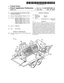
[0011] FIG. 1 is a partially sectioned, isometric view of an embodiment of a paraffin removal system.
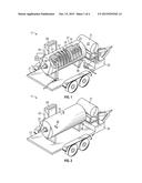
[0012] FIG. 2 is an isometric view of an embodiment of a paraffin removal system.
[0013] FIG. 3 is a top view of the embodiment of the paraffin removal system of FIG. 2.
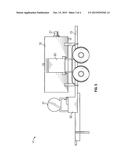
[0014] FIG. 4 is a side view of the embodiment of the paraffin removal system of FIG. 2.
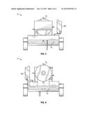
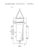
[0015] FIG. 5 is a front view of the embodiment of the paraffin removal system of FIG. 2.
[0016] FIG. 6 is a rear view of the embodiment of the paraffin removal system of FIG. 2.
[0017] The use of the same reference symbols in different drawings indicates similar or identical items.
DETAILED DESCRIPTION
[0018] Embodiments of a system, method and apparatus for paraffin removal are disclosed and illustrated in FIGS. 1-6. For example, FIG. 1 depicts an embodiment of a paraffin removal system 11 for producing oil wells. System 11 may include a base 13. The base 13 may include a trailer, a skid, or the like, in some versions. The system 11 also may include a heating tank 15 mounted to the base 13. The heating tank 15 may be generally cylindrical, and may include an axis 17. Versions of the heating tank 15 may be insulated.
[0019] Some embodiments of system 11 may include one or more tubular coils 19 mounted inside the heating tank 15. The coil 19 may extend substantially along the axis 17. The coil 19 may be configured to circulate fluids therethrough from a producing oil well. Other embodiments of the system 11 may include a double coil (not shown) for longer retention time of the circulated fluids to treat deeper wells. The double coil may comprise a coiled length that is greater, or two coils with different-sized diameters. The smaller of the two coils may be located inside the larger of the two coils, but are otherwise continuous with each other.
[0020] Embodiments of the system 11 may be only electrical. The system 11 may be configured to not use any flames. System 11 may include one or more electrical heating elements 21 (e.g., two shown) mounted inside the heating tank 15. The heating elements 21 may be located adjacent the tubular coil 19. The electrical heating elements 21 may be configured to heat a liquid 23 located inside and substantially filling the heating tank 15.
[0021] In other embodiments, the system 11 may include a chemical tank 31. The chemical tank 31 may be mounted to the base 13, and may include a catch pan 33. A pump 35 may be configured to dispense a selected amount of paraffin treatment chemical 37 from the chemical tank 31 to the tubular coil 19 via inlet 36. Inlet 36 also receives fluids and circulated fluid from the well. The fluids circulated through tubular coil 19 exit the heating tank 15 via outlet 38, where they are delivered to the well as described herein.
[0022] Selected embodiments may include a thermostat 41 for selectively controlling a temperature of the one or more electrical heating elements 21. For example, the thermostat 41 may independently control each of the electrical heating elements 21.
[0023] Embodiments of the system 11 may further comprise at least one wave breaker 51 inside the heating tank 15 to stabilize the liquid 23 therein. Some embodiments of the system 11 may further comprise an electrical generator 61 and a control panel 63. The electrical generator 61 and control panel 63 may be mounted to the base 13, and may be configured to operate the system 11 autonomously from any other power source.
[0024] Other features may include configuring the system 11 such that it does not form a hydrostatic head with the circulated fluids in a treated well. A hydrostatic head is not formed because the well is circulated with the combined oil and water that is naturally producing from the well formation. In contrast, hydrostatic head pressure is forced through pump trucks and conventional hot water and hot oiling techniques at the surface, causing hydrostatic head pressure. Depending on the amount of daily production, a slight head pressure may occur depending on the volumes and depths of the wells. Slight head pressures can be calculated with well bore schematics and accurate production volumes. In some versions, no fluid is forced back down hole with added pressure. The pumping unit is merely allowed to circulate the heated fluid back down hole.
[0025] Moreover, the system may be configured to operate continuously (rather than selectively or intermittently) while a well is producing. The system can treat a well in a continuous manner (e.g., selectively and/or intermittently heating and/or adding chemicals) after determining the amount of fluid the well produces daily. Extensive hydrocarbon analysis can provide treatment durations. Such treatments can also be determined through mechanical devices at the well, the pump off controller (POC) of the well and/or with an intermittent timer.
[0026] The embodiments disclosed herein may provide some advantages compared to prior art solutions. For example, the embodiments may provide a safer, more cost effective and efficient alternative for removal of paraffin from producing wells. Versions of the paraffin removal system are safer since they do not require the use of flames. Some embodiments do not form a hydrostatic head, are more economical, have the ability to treat marginal wells, do not damage existing formations, and can provide an extended heating duration with excellent results.
[0027] Embodiments of the paraffin removal system can include a trailer-mounted electrical heating unit that is connected to a producing oil well. It has the ability to heat and add chemicals to the circulating fluid in the well for extended periods of time. This ability to reach desired temperatures throughout the well while using chemistry for extended periods of time can provide a superior method of paraffin removal. Representative chemicals may include an oil-soluble water dispersible paraffin dispersant. Other chemistry that may be used can include paraffin solvents, acid surfactants, non ionic surfactants, oil soluble corrosion inhibitors, and hydrochloric acid (e.g., 15% HCL).
[0028] Embodiments of a method of use may include a system user arriving on location and parking a trailer on a side of the pumping unit and wellhead. An electrical grounding cable may be attached to natural ground. An inlet side of the coil on the trailer may be connected to, for example, the ball valve on an atmospheric side of tubing off a pumping tee via a hammer union. A discharge side of the coil on the trailer may be connected to a ball valve on the atmospheric side of the casing, such as via a hammer union. After all connections to the trailer are safely fastened to the wellhead, the ball valves on the trailer coil are opened, as well as the ball valves on both the inlet and discharge hoses.
[0029] The well is ready to be treated for paraffin by opening the ball valves on the wellhead. In some versions, a power cable is connected to a main panel of the pumping unit. A system thermostat may be pre-programmed to operate at about 300° F., or another desired temperature. For wells that utilize fiberglass rod strings, a lower temperature may be desired to prevent breakdown of epoxy. In addition, one or more desired chemicals may be added to the distribution tank on trailer. During operation, as fluid begins to circulate through the coil on the trailer, the chemical may be injected into the inlet stream of fluid by way of a pump which may be mounted adjacent the chemical tank. The length of time of paraffin treatment can depend on the amount of paraffin needing to be dispersed. After desired treatment is completed, the trailer can then be disconnected and moved to another location, if desired.
[0030] In some embodiments, the trailer may include a tubular vessel or tank, such as one having dimensions of approximately 3 feet in diameter, and 7 feet in axial length. The tank may be formed from a material such as a 0.25-inch thick, rolled plate steel. The internal coil within the tank can have various dimensions, such as an overall length of about 160 feet and a diameter of about 2.375 inches. Embodiments of the coil can be formed from a material such as seamless steel tubing, and pressure tested to about 1450 psi. The coil can be submerged in the tank in a liquid insulator, such as at least about 300 gallons of tri-ethlene glycol. The trailer may include a catch pan mounted on a front thereof for chemical containment. A smaller chemical tank may be mounted on a stand, which may be positioned in a center of the catch pan. A pump may be used to inject chemical into an inlet of the coil tubing. Raised face flanges may be positioned on each end of the trailer. The tank may include immersion heating elements, which may be rated at about 350° F., which may be mounted on flanges within the tank.
[0031] The system may further include hoses, such as cloth-braided hoses. In some versions, the hoses can have a 1-inch in diameter, a length of about 20 feet, and can be pressure rated to about 2500 psi. The system also may include an electrical panel, such as a size two, 480-volt electrical panel. The panel can run the two heating elements individually, or together. This design can be advantageous in situations limited by electrical service. A transformer, such as a 480 V to 110 V transformer, may be used in the panel to run a chemical transfer pump through a 110 V electrical outlet. The pump can be set to inject a desired amount of chemicals into the upstream side (inlet) of the system. A digital thermostat may be employed to operate the heating elements. The system may employ resistance temperature detectors (RTD) for this aspect. For example, two-wire RTDs may be used to detect the temperature within the system, and to prevent the heating elements from overheating.
[0032] In some embodiments, the pressure on the inlet hose may be about 400 psi. A rod pump, which is a positive displacement pump, may be used for circulation by the device. In some situations, a pressuring up of surface wellhead may occur if a blockage is seen at the surface of the well. If the preset maximum pressure of the system is exceeded, a switch will turn off the pumping unit and the trailer panel power. Such a system averts a blowout, and prevents fluid from escaping the system and contaminating the environment.
[0033] Still other optional features may include one or more of the following items: coiled tubing of any desired size and length; an optional double coil for longer retention time to treat deeper wells; one or more wave breakers to stabilize liquids when transferring the trailer to prevent damage to the heating elements; a mounted LMI pump to deliver desired chemical at an optimal rate; an ability to additionally treat flow lines and tanks by adjusting and holding temperature; running the heating elements together or independently; thermostat controlled temperature to allow the ability to selectively treat flow lines, fiberglass rods, and steel rods without thermal damage; a mounted generator to provide power when electricity is not available at the treatment site; mounting the vessel either on a trailer or on a skid, depending on type of location being accessed; insulating the vessel to maintain heat in colder climates; and an environmentally-friendly method for removing paraffin.
[0034] This written description uses examples to disclose the embodiments, including the best mode, and also to enable those of ordinary skill in the art to make and use the invention. The patentable scope is defined by the claims, and may include other examples that occur to those skilled in the art. Such other examples are intended to be within the scope of the claims if they have structural elements that do not differ from the literal language of the claims, or if they include equivalent structural elements with insubstantial differences from the literal languages of the claims.
[0035] Note that not all of the activities described above in the general description or the examples are required, that a portion of a specific activity may not be required, and that one or more further activities may be performed in addition to those described. Still further, the order in which activities are listed are not necessarily the order in which they are performed.
[0036] In the foregoing specification, the concepts have been described with reference to specific embodiments. However, one of ordinary skill in the art appreciates that various modifications and changes can be made without departing from the scope of the invention as set forth in the claims below. Accordingly, the specification and figures are to be regarded in an illustrative rather than a restrictive sense, and all such modifications are intended to be included within the scope of invention.
[0037] As used herein, the terms "comprises," "comprising," "includes," "including," "has," "having" or any other variation thereof, are intended to cover a non-exclusive inclusion. For example, a process, method, article, or apparatus that comprises a list of features is not necessarily limited only to those features but may include other features not expressly listed or inherent to such process, method, article, or apparatus. Further, unless expressly stated to the contrary, "or" refers to an inclusive-or and not to an exclusive-or. For example, a condition A or B is satisfied by any one of the following: A is true (or present) and B is false (or not present), A is false (or not present) and B is true (or present), and both A and B are true (or present).
[0038] Also, the use of "a" or "an" are employed to describe elements and components described herein. This is done merely for convenience and to give a general sense of the scope of the invention. This description should be read to include one or at least one and the singular also includes the plural unless it is obvious that it is meant otherwise.
[0039] Benefits, other advantages, and solutions to problems have been described above with regard to specific embodiments. However, the benefits, advantages, solutions to problems, and any feature(s) that may cause any benefit, advantage, or solution to occur or become more pronounced are not to be construed as a critical, required, or essential feature of any or all the claims.
[0040] After reading the specification, skilled artisans will appreciate that certain features are, for clarity, described herein in the context of separate embodiments, may also be provided in combination in a single embodiment. Conversely, various features that are, for brevity, described in the context of a single embodiment, may also be provided separately or in any subcombination. Further, references to values stated in ranges include each and every value within that range.
User Contributions:
Comment about this patent or add new information about this topic:
Images included with this patent application:
 |  |
 |  |
 |
| New patent applications in this class: | |
| Date | Title |
|---|---|
| 2022-05-05 | Hydraulic rotary side-swing elevator |
| 2016-07-14 | Tool catch |
| 2016-07-07 | Mousehole apparatus |
| 2016-06-09 | Reciprocating pump drive assembly |
| 2016-04-28 | Petroleum instrument salvaging system and salvaging head |
| Top Inventors for class "Wells" | |
| Rank | Inventor's name |
|---|---|
| 1 | Michael L. Fripp |
| 2 | Jean Marc Lopez |
| 3 | Michael H. Johnson |
| 4 | Jørgen Hallundbaek |
| 5 | Dennis P. Nguyen |