Patent application title: COATED POLYMER CLAD OPTICAL FIBER
Inventors:
Shingo Matsushita (Sakura-Shi, JP)
Assignees:
FUJIKURA LTD.
IPC8 Class: AG02B602FI
USPC Class:
Class name:
Publication date: 2015-10-08
Patent application number: 20150285991
Abstract:
A coated polymer clad optical fiber of the invention includes: a polymer
cladding layer that is formed around an optical fiber made of
silica-based glass and has a refractive index lower than the refractive
index of the silica-based glass; and a protective coating layer formed
around the polymer cladding layer. The thickness of the polymer cladding
layer is 3.0 or more times the thickness of the protective coating layer.Claims:
1. A coated polymer clad optical fiber comprising: a polymer cladding
layer formed around an optical fiber made of silica-based glass, the
polymer cladding layer having a refractive index lower than a refractive
index of the silica-based glass; and a protective coating layer formed
around the polymer cladding layer; wherein a thickness of the polymer
cladding layer is 3.0 or more times a thickness of the protective coating
layer.
2. The coated polymer clad optical fiber according to claim 1, wherein the protective coating layer has a type D durometer hardness of greater than or equal to 20.
3. The coated polymer clad optical fiber according to claim 1, wherein a resin used to form the protective coating layer is a thermosetting resin.
4. The coated polymer clad optical fiber according to claim 1, wherein a resin used to form the polymer cladding layer is a thermosetting resin.
5. A coated polymer clad optical fiber comprising: a polymer cladding layer formed around an optical fiber made of silica-based glass, the polymer cladding layer having a refractive index lower than a refractive index of the silica-based glass; at least one or more buffer layers formed around the polymer cladding layer; and a protective coating layer formed around the buffer layers, wherein a total thickness of the polymer cladding layer and the buffer layers is 1.5 or more times a thickness of the protective coating layer.
6. The coated polymer clad optical fiber according to claim 5, wherein the protective coating layer has a type D durometer hardness of greater than or equal to 20.
7. The coated polymer clad optical fiber according to claim 5, wherein a resin used to form the protective coating layer is a thermosetting resin.
8. The coated polymer clad optical fiber according to claim 5, wherein a resin used to form the buffer layers has a type A durometer hardness of 20 to 80.
Description:
CROSS-REFERENCE TO RELATED APPLICATION
[0001] This application is based on and claims priority from Japanese Patent Application No. 2014-079423 filed on Apr. 8, 2014, the contents of which are incorporated herein by reference in their entirety.
BACKGROUND OF THE INVENTION
[0002] 1. Field of the Invention
[0003] The present invention relates to a coated polymer clad optical fiber used in an optical fiber, particularly, used in a fiber laser, or the like.
[0004] 2. Description of the Related Art
[0005] Optical fibers that are required to have high numerical aperture (hereinbelow, referred to as "high NA") are used, particularly, it is necessary for an optical fiber used in a fiber laser (hereinbelow, referred to "laser fiber") to transmit high density light.
[0006] In recent years, power of the fiber laser further increases, a fiber laser is in a commercial reality which realizes a kW class optical output such that it is used to cut or weld a metal, heat melting, or the like, a further souped-up optical fiber is required.
[0007] In order to realize an increase in power of the fiber laser, it is necessary to launch a further-large amount of pumping light into an optical fiber, and it is desirable to develop an optical fiber that realizes a high NA such that the NA is greater than or equal to 0.5 (hereinbelow, "high NA" in the invention means an NA of greater than or equal to 0.5).
[0008] As a polymer cladding material used to form a laser fiber, ultraviolet curable fluorinated acrylate resins are mainly used.
[0009] Such ultraviolet curable fluorinated acrylate resins originally have a low level of adhesion with respect to glass. Furthermore, in the case of adding a large amount of fluorine into the resins in order to realize a high NA, the level of adhesion with respect to glass becomes more degraded.
[0010] For this reason, even if a high NA can be realized as a result of using ultraviolet curable resins, there is a problem in that the transmission loss rapidly deteriorates in high humidity.
[0011] Because of this, in the disclosure of Japanese Unexamined Patent Application, First Publication No. 2013-41060, as a result of using, as a polymer cladding material, a cladding material containing a perfluoroether polymer that is cured by cross-linking due to a hydrosilylation reaction, a high NA is realized and the cladding material has hydrophobicity; additionally, as a result of introducing an alkoxy group that combines with silicon atoms in the cladding thereto, the moisture resistance is improved.
[0012] Conventionally, it is said that it is preferable that the fracture stress (tensile strength) of the polymer cladding material be greater than or equal to 10 MPa.
[0013] However, in the case of increasing an amount of fluorine that is to be introduced into a polymer cladding material in order to realize a high NA, the fracture stress of the resin cannot be sufficiently increased such that, for example, the fracture stress becomes less than or equal to 1 MPa.
[0014] Also, regarding a laser fiber, a screening test is carried out which previously removes a low-strength portion in order to ensure the mechanical reliability thereof. However, in the case of a polymer cladding material having a low fracture stress, due to an external force such as ironing which is applied thereto in the screening test, a polymer cladding material is broken or peeled off from glass, and there are problems in that pumping light guided in the glass cannot be confined and leakage of the excitation light occurs.
SUMMARY OF THE INVENTION
[0015] The invention was conceived in view of the above-described circumstances and an object thereof is to provide a coated polymer clad optical fiber which has a high level of resistance to ironing and can reduce excitation loss.
[0016] A coated polymer clad optical fiber according to an first aspect of the invention includes: a polymer cladding layer formed around an optical fiber made of silica-based glass, the polymer cladding layer having a refractive index lower than the refractive index of the silica-based glass; and a protective coating layer formed around the polymer cladding layer; wherein the thickness of the polymer cladding layer is 3.0 or more times the thickness of the protective coating layer.
[0017] In the coated polymer clad optical fiber according to the first aspect of the invention, it is preferable that the protective coating layer have a type D durometer hardness of greater than or equal to 20.
[0018] In the coated polymer clad optical fiber according to the first aspect of the invention, it is preferable that the resin used to form the protective coating layer be a thermosetting resin.
[0019] In the coated polymer clad optical fiber according to the first aspect of the invention, it is preferable that the resin used to form the polymer cladding layer be a thermosetting resin.
[0020] A coated polymer clad optical fiber according to a second aspect of the invention includes: a polymer cladding layer formed around an optical fiber made of silica-based glass, the polymer cladding layer having a refractive index lower than the refractive index of the silica-based glass; at least one or more buffer layers formed around the polymer cladding layer; and a protective coating layer formed around the buffer layers, wherein the total thickness of the polymer cladding layer and the buffer layers is 1.5 or more times the thickness of the protective coating layer.
[0021] In the coated polymer clad optical fiber according to the second aspect of the invention, it is preferable that the protective coating layer have a type D durometer hardness of greater than or equal to 20.
[0022] In the coated polymer clad optical fiber according to the second aspect of the invention, it is preferable that a resin used to form the protective coating layer be a thermosetting resin.
[0023] In the coated polymer clad optical fiber according to the second aspect of the invention, it is preferable that the resin used to form the buffer layers have a type A durometer hardness of 20 to 80.
[0024] According to the above-described aspects of the invention, it is possible to provide a coated polymer clad optical fiber which has a high level of resistance to ironing and can reduce an excitation loss.
BRIEF DESCRIPTION OF THE DRAWINGS
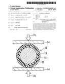
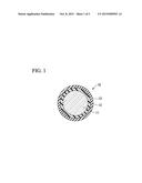
[0025] FIG. 1 is a cross-sectional view showing an example of a coated polymer clad optical fiber according to a first embodiment.
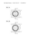
[0026] FIG. 2A is a cross-sectional view showing the case where an external force is applied to an optical fiber including a soft protection resin layer.
[0027] FIG. 2B is a cross-sectional view showing the case where an external force is applied to an optical fiber including a hard protection resin layer.
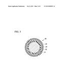
[0028] FIG. 3 is a cross-sectional view showing an example of a coated polymer clad optical fiber according to a second embodiment.
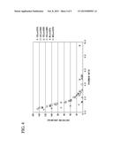
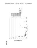
[0029] FIG. 4 is a chart showing, as an example, the relationships between the thickness ratios according to the first embodiment and excitation losses.
[0030] FIG. 5 is a chart showing, as an example, the relationships between the thickness ratios according to the second embodiment and excitation losses.
DETAILED DESCRIPTION OF THE INVENTION
[0031] Hereinafter, preferred embodiments will described with reference to drawings.
[0032] FIG. 1 is a cross-sectional view schematically showing a coated polymer clad optical fiber 10 according to a first embodiment.
[0033] The coated polymer clad optical fiber 10 has a cross-section structure in which a polymer cladding layer 12 is formed around an optical fiber made of silica-based glass 11 and a protective coating layer 13 is formed around the polymer cladding layer 12.
[0034] The polymer cladding layer 12 has a refractive index lower than the refractive index of silica-based glass forming the optical fiber 11.
[0035] FIGS. 2A and 2B are schematic views showing the cases where an external force is applied to the coated polymer clad optical fiber 10.
[0036] FIG. 2A shows the case where a resin used to form the protective coating layer 13 is soft.
[0037] FIG. 2B shows the case where a resin used to form the protective coating layer 13 is hard.
[0038] In the case where the protective coating layer 13 is soft, as a result of an external force that is applied to the coated polymer clad optical fiber 10, both the protective coating layer 13 and the polymer cladding layer 12 are deformed, and the polymer cladding layer 12 is thereby broken.
[0039] For example, in the case where the coated polymer clad optical fiber 10 sandwiched between a pair of plate-shaped members 14 and an external force 15 is applied thereto, destruction 17 occurs in the polymer cladding layer 12 due to the opposed action 16 received from the optical fiber 11 made of hard glass and the external force 15 received from the plate-shaped members 14.
[0040] On the other hand, in the case where the protective coating layer 13 is hard, since the protective coating layer 13 is hardly deformed even where an external force is applied to the coated polymer clad optical fiber 10, the polymer cladding layer 12 is not deformed, and breaking of the polymer cladding layer 12 never happens.
[0041] In order to ensure sufficiently resistance to ironing, it is preferable to form the protective coating layer 13 by use of a resin having a Type D durometer hardness of 20 or more (the hardness is greater than or equal to D20) as defined by JIS K 6253.
[0042] More preferably, as a result of forming the protective coating layer 13 by use of a hard resin having a Type D durometer hardness of 70 or more, it is possible to improve resistance to ironing (in the description below, the hardness of the invention is a hardness that is measured by durometer hardness measurement, and a Type A durometer and Type D durometer are simply referred to as A and D, respectively).
[0043] However, in order to improve resistance to ironing, in the case of using a hard resin to form the protective coating layer 13, although the resistance to ironing is improved, an excitation loss is sometimes degraded.
[0044] Particularly, in the case of forming the protective coating layer 13 by use of a thermosetting resin such as a silicone resin or a polyimide resin in order to improve the heat resistance of the coated polymer clad optical fiber 10, the excitation loss is significantly deteriorated.
[0045] The reason that, an excitation loss is significantly deteriorated as a result of forming the protective coating layer 13 by use of a thermosetting resin having a high hardness, is considered to be as follows.
[0046] When an optical fiber is coated with a thermosetting resin, a curing reaction mechanism varies depending on the kinds of resin. In all cases, after the periphery of an optical fiber is coated with a resin, as a result of heating the resin under high temperature conditions using a bridging device such as an electrically-heated reactor, curing of the resin is prompted, and a state of the resin is thereby changed from a flowable state to a solid state.
[0047] At this time, since the structure of the resin is solidified in a high temperature state, after the optical fiber coated with the resin is discharged from the bridging device, heat shrinkage occurs during the lowering of the resin temperature to room temperature.
[0048] In the case of using a resin having a high hardness, it is conceivable that a lateral pressure that is applied to the polymer cladding layer 12 located inside the protective coating layer 13 excessively increases due to the heat shrinkage of the protective coating layer 13, and the excitation loss thereby increases (deterioration).
[0049] Based on the above consideration, the inventor has been intensively researched to reduce the effect of the lateral pressure applied from the protective coating layer 13 to the polymer cladding layer 12. As a result, in the invention, it is found out that the ratio of the polymer cladding layer 12 to the protective coating layer 13 is correlated to excitation loss, and that, as a result of setting the thickness of the polymer cladding layer 12 to be 3.0 or more times the thickness of the protective coating layer 13, it is possible to manufacture a coated polymer clad optical fiber 10 which has heat resistance and achieves both a resistance to ironing and a low degree of excitation loss.
[0050] As a resin used to form the polymer cladding layer 12 (a polymer cladding material), a fluorine resin, a fluorinated acrylate resin, or the like is adopted.
[0051] The polymer cladding material is a ultraviolet curable resin, a thermosetting resin, or the like. In terms of heat resistance, it is preferable to use a thermosetting resin as the polymer cladding material.
[0052] FIG. 3 is a cross-sectional view schematically showing a coated polymer clad optical fiber 20 according to a second embodiment.
[0053] The coated polymer clad optical fiber 20 has a cross-section structure in which a polymer cladding layer 22 is formed around an optical fiber 21 made of silica-based glass, at least one or more buffer layer 23 is formed around the polymer cladding layer 22, and a protective coating layer 24 is formed around the buffer layer 23.
[0054] The polymer cladding layer 22 has a refractive index lower than the refractive index of silica-based glass forming the optical fiber 21.
[0055] The resin (a polymer cladding material) used to form the polymer cladding layer 22 may be the same as that in the first embodiment.
[0056] A polymer cladding material is expensive more than a generally-used resin. Therefore, it is not preferable to increase the thickness of the polymer cladding layer 22 because the cost thereof increases.
[0057] Consequently, the inventor researched the adoption of a three-layered structure having the buffer layer 23 interposed between the polymer cladding layer 22 and the protective coating layer 24 and thereby realize a fiber structure that can satisfy both resistance to ironing and a low degree of excitation loss while reducing the thickness of the polymer cladding layer 22. As a result, it is found out that, by setting the total thickness of the polymer cladding layer 22 and the buffer layer 23 to be 1.5 or more times the thickness of the protective coating layer 24, the coated polymer clad optical fiber 20 can be manufactured which satisfies both resistance to ironing and a low degree of excitation loss. The coated polymer clad optical fiber of the second embodiment is realized based on the above consideration.
[0058] Particularly, the hardness of a resin used to form the buffer layer 23 is preferably approximately A20 to A80, preferably A20 or more and A80 or less, and more preferably less than or equal to A30.
[0059] In the case of forming the buffer layer 23 by use of a resin made of gel or grease which has a hardness lower than A20 and is measured by penetration, since the protective coating layer 24 is deformed by ironing, the external shape in appearance of the optical fiber cannot be maintained and a resistance to ironing cannot be obtained.
[0060] Adversely, in the case of forming the buffer layer 23 by use of a resin which has a Type D durometer hardness of higher than A80, the effect of the buffer layer 23 cannot be sufficiently obtained, and a function due to the three-layered structure cannot be obtained.
[0061] In other cases where the optical fiber has a three-layered coating structure, the thickness ratio of the polymer cladding layer 22 to the buffer layer 23 is not particularly limited, and the number of the buffer layer 23 may be greater than or equal to two.
[0062] It is preferable that the thickness of the polymer cladding layer 22 be greater than or equal to 3 μm.
[0063] In the second embodiment, the resin used to form the protective coating layer 24 may be the same as that in the first embodiment.
[0064] It is preferable that the hardness of the resin used to form the protective coating layer 24 be greater than or equal to D20.
[0065] Furthermore, it is preferable that the resin used to form the protective coating layer 24 be a thermosetting resin.
[0066] While preferred embodiments of the invention have been described and illustrated above, it should be understood that these are exemplary of the invention and are not to be considered as limiting. Additions, omissions, substitutions, and other modifications can be made without departing from the scope of the present invention. Accordingly, the invention is not to be considered as being limited by the foregoing description, and is only limited by the scope of the appended claims.
[0067] Each of the optical fibers 11 and 21 may function as a glass core relative to the polymer cladding layers 12 and 22. Each of the optical fibers 11 and 21 may include core and cladding.
[0068] Silica-based glass forming the optical fibers 11 and 21 may be made of pure silica glass or may be made of silica glass into which fluorine (F), germanium (Ge), or the like is doped.
[0069] An optical fiber which is used to transmit signal light preferably include: a single-layer glass cladding provided around a glass core; and a polymer cladding layer provided around the glass cladding.
[0070] An optical fiber which is used to transmit pumping light preferably include a polymer cladding layer that is directly provided on the periphery of a glass core.
[0071] In the case of preventing reflected light from entering into a light source such as a laser diode (LD), a two-layered glass cladding (inner cladding and outer cladding) may be provided around a glass core, and a polymer cladding layer may be provided around a glass cladding.
[0072] Typically, the outer diameter (fiber diameter, glass diameter) of each of the optical fibers 11 and 21 is 125 μm. The invention is obviously applicable to optical fibers having the other diameter.
[0073] Generally, as the glass diameter becomes smaller in an optical fiber, the number of light reflection at the boundary face between the polymer cladding layer and the glass increases. Accordingly, in the case of using the same polymer cladding material, a value of the excitation loss which can reach becomes larger. However, the value of the excitation loss which is caused by the cover member shown in the embodiments of invention does not depend on the fiber diameter.
EXAMPLES
[0074] Hereinbelow, the invention will be particularly described with reference to Examples.
Test Example of First Embodiment
[0075] In the above-described first embodiment, a resin having a hardness of D20 or more is used to form the protective coating layer 13, and the thickness of the polymer cladding layer 12 is 3.0 or more times the thickness of the protective coating layer 13. As a result, it is possible to manufacture the coated polymer clad optical fiber 10 that satisfies both resistance to ironing and a low degree of excitation loss.
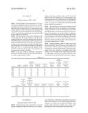
[0076] Of the manufactured coated polymer clad optical fibers 10 shown in Tables 1 to 6, the initial character denoted by "C" of the number of the coated polymer clad optical fibers are Comparative Examples. That is, the coated polymer clad optical fibers shown by C1A to C39A represent Comparative Examples.
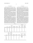
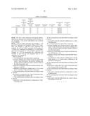
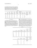
[0077] In Tables 1 to 6, the units of "FIBER DIAMETER", "CLADDING DIAMETER", "PROTECTIVE COATING DIAMETER", "THICKNESS OF CLADDING", and "THICKNESS OF PROTECTIVE COATING LAYER" are "μ", the units of "EXCITATION LOSS" and "INCREMENT IN EXCITATION LOSS" are "dB/km", and the units thereof which are commonly used are omitted.
[0078] The "FIBER DIAMETER" represents a glass diameter of the optical fiber 11. "CLADDING DIAMETER" and "THICKNESS OF CLADDING" represent the outer diameter and the thickness of the polymer cladding layer 12, respectively. "PROTECTIVE COATING DIAMETER" and "THICKNESS OF PROTECTIVE COATING LAYER" represent the outer diameter and the thickness of the protective coating layer 13, respectively.
[0079] "THICKNESS RATIO" is the ratio of "THICKNESS OF CLADDING" to "THICKNESS OF PROTECTIVE COATING LAYER".
Test Example 1
Reference Numbers 1A to 2A and C1A to C3A
[0080] The optical fiber 11 having a fiber diameter of 125 μm was prepared. With respect to the optical fiber, the polymer cladding layer 12 was formed by use of a thermosetting resin having a refractive index of 1.35 or less, and the protective coating layer 13 was formed by use of a thermosetting resin having a hardness of D75. As a result, the coated polymer clad optical fiber 10 having a high NA was produced.
[0081] The thickness of the polymer cladding layer 12 and the thickness of the protective coating layer 13 were varied, the coated polymer clad optical fibers 10 using them were produced, and the excitation losses thereof were measured. As shown in Table 1, under the condition of the coated polymer clad optical fiber 10 in which the thickness of the polymer cladding layer 12 is 3 or more times the thickness of the protective coating layer 13, the value of the excitation loss was stable at approximately 3 dB/km.
[0082] Next, regarding Numbers 1 A and 2A of the coated polymer clad optical fibers 10 (having overall length of 20 km), in order to evaluate resistance to ironing of the produced coated polymer clad optical fibers 10, the coated polymer clad optical fibers were subjected to rewinding while being extended so as to be longer than the original length thereof by 2% of the length. Thereafter, visible light was launched into the optical fiber 11, and whether or not the excitation light leaked was evaluated. As a result of the evaluation, it was observed that the leakage of the excitation light (generation of bright spot) did not occur, the excitation loss thereof was not varied, and excellent resistance to ironing was obtained.
TABLE-US-00001 TABLE 1 THICK- DEGREE OF CLAD- PROTEC- THICK- NESS OF HARDNESS OF GENERA- INCREMENT FIBER DING TIVE NESS OF PROTECTIVE PROTECTIVE THICK- EXCITA- TION OF IN EXCITA- NUM- DIAM- DIAM- COATING CLAD- COATING COATING NESS TION BRIGHT TION BER ETER ETER DIAMETER DING LAYER LAYER RATIO LOSS SPOT LOSS 1A 125 220 250 47.5 15 D75 3.2 3.1 ABSENCE 0 2A 125 220 240 47.5 10 D75 4.8 3 ABSENCE 0 C1A 125 177 250 26 36.5 D75 0.7 130 -- -- C2A 125 180 235 27.5 27.5 D75 1.0 105 -- -- C3A 125 180 230 27.5 25 D75 1.1 86.45 -- -- C4A 125 190 230 32.5 20 D75 1.0 45 -- -- C5A 125 197 230 36 16.5 D75 2.2 24 -- -- C6A 125 200 230 37.5 15 D75 2.5 12 -- --
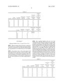
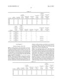
Test Example 2
Reference Numbers 3A to 5A and C7A to C12A
[0083] With the exception that the fiber diameter is 80 μm, the coated polymer clad optical fiber 10 having high NA was produced in a way similar to the case of Test Example 1.
[0084] The excitation losses of the coated polymer clad optical fibers 10 were measured. As shown in Table 2, under the condition of the coated polymer clad optical fiber 10 in which the thickness of the polymer cladding layer 12 is 3 or more times the thickness of the protective coating layer 13, the value of the excitation loss was stable at approximately 10 dB/km.
[0085] Next, regarding Numbers 3A to 5A of the coated polymer clad optical fibers 10 (having overall length of 20 km), in order to evaluate resistance to ironing of the produced coated polymer clad optical fibers 10, the coated polymer clad optical fibers were subjected to rewinding while being extended so as to be longer than the original length thereof by 2% of the length. Thereafter, visible light was launched into the optical fiber 11, and whether or not the excitation light leaked was evaluated. As a result of the evaluation, it was observed that the leakage of the excitation light (generation of bright spot) did not occur, the excitation loss thereof was not varied, and excellent resistance to ironing was obtained.
TABLE-US-00002 TABLE 2 DEGREE OF THICKNESS HARDNESS OF OF PROTECTIVE THICKNESS PROTECTIVE PROTECTIVE FIBER CLADDING COATING OF COATING COATING NUMBER DIAMETER DIAMETER DIAMETER CLADDING LAYER LAYER 3A 80 170 200 45 15 D75 4A 80 220 250 70 15 D75 5A 80 270 290 95 10 D75 C7A 80 140 230 30 45 D75 C8A 80 140 210 30 35 D75 C9A 80 150 200 35 25 D75 C10A 80 160 205 40 22.5 D75 C11A 80 165 200 42.5 17.5 D75 C12A 80 175 210 47.5 17.5 D75 GENERATION INCREMENT OF IN THICKNESS EXCITATION BRIGHT EXCITATION NUMBER RATIO LOSS SPOT LOSS 3A 3.0 10 ABSENCE 0 4A 4.7 9.8 ABSENCE 0 5A 9.5 9.7 ABSENCE 0 C7A 0.7 130 -- -- C8A 0.9 105 -- -- C9A 1.4 70 -- -- C10A 1.8 38 -- -- C11A 2.4 20 -- -- C12A 2.7 15 -- --
Test Example 3
Reference Numbers 6A to 7A and Cl3A to Cl8A
[0086] With the exception that the fiber diameter is 400 μm, the coated polymer clad optical fiber 10 having high NA was produced in a way similar to the case of Test Example 1.
[0087] The excitation losses of the coated polymer clad optical fibers 10 were measured. As shown in Table 3, under the condition of the coated polymer clad optical fiber 10 in which the thickness of the polymer cladding layer 12 is 3 or more times the thickness of the protective coating layer 13, the value of the excitation loss was stable at approximately 3 dB/km.
[0088] Next, regarding Numbers 6A and 7A of the coated polymer clad optical fibers 10 (having overall length of 20 km), in order to evaluate resistance to ironing of the produced coated polymer clad optical fibers 10, the coated polymer clad optical fibers were subjected to rewinding while being extended so as to be longer than the original length thereof by 2% of the length. Thereafter, visible light was launched into the optical fiber 11, and whether or not the excitation light leaked was evaluated. As a result of the evaluation, it was observed that the leakage of the excitation light (generation of bright spot) did not occur, the excitation loss thereof was not varied, and excellent resistance to ironing was obtained.
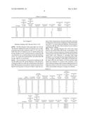
TABLE-US-00003 TABLE 3 DEGREE OF THICKNESS HARDNESS OF OF PROTECTIVE THICKNESS PROTECTIVE PROTECTIVE FIBER CLADDING COATING OF COATING COATING NUMBER DIAMETER DIAMETER DIAMETER CLADDING LAYER LAYER 6A 400 510 545 55 17.5 D75 7A 400 550 580 75 15 D75 C13A 400 440 520 20 40 D75 C14A 400 455 520 27.5 32.5 D75 C15A 400 465 520 32.5 27.5 D75 C16A 400 470 520 35 25 D75 C17A 400 485 520 42.5 17.5 D75 C18A 400 485 515 42.5 15 D75 GENERATION INCREMENT OF IN THICKNESS EXCITATION BRIGHT EXCITATION NUMBER RATIO LOSS SPOT LOSS 6A 3.1 2.8 ABSENCE 0 7A 5.0 2.9 ABSENCE 0 C13A 0.5 145 -- -- C14A 0.8 115 -- -- C15A 1.2 90 -- -- C16A 1.4 57 -- -- C17A 2.4 12 -- -- C18A 2.8 6 -- --
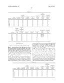
Test Example 4
Reference Numbers 8A to 9A and C19A to C24A
[0089] With the exception that the protective coating layer 13 is formed by use of a thermosetting resin having a hardness of D50, the coated polymer clad optical fiber 10 having high NA was produced in a way similar to the case of Test Example 1.
[0090] The excitation losses of the coated polymer clad optical fibers 10 were measured. As shown in Table 4, under the condition of the coated polymer clad optical fiber 10 in which the thickness of the polymer cladding layer 12 is 3 or more times the thickness of the protective coating layer 13, the value of the excitation loss was stable at approximately 3 dB/km.
[0091] Next, regarding Numbers 8A and 9A of the coated polymer clad optical fibers 10 (having overall length of 20 km), in order to evaluate resistance to ironing of the produced coated polymer clad optical fibers 10, the coated polymer clad optical fibers were subjected to rewinding while being extended so as to be longer than the original length thereof by 2% of the length. Thereafter, visible light was launched into the optical fiber 11, and whether or not the excitation light leaked was evaluated. As a result of the evaluation, it was observed that the leakage of the excitation light (generation of bright spot) did not occur, the excitation loss thereof was not varied, and excellent resistance to ironing was obtained.
TABLE-US-00004 TABLE 4 DEGREE OF THICKNESS HARDNESS OF OF PROTECTIVE THICKNESS PROTECTIVE PROTECTIVE FIBER CLADDING COATING OF COATING COATING NUMBER DIAMETER DIAMETER DIAMETER CLADDING LAYER LAYER 8A 125 225 250 50 12.5 D50 9A 125 230 250 52.5 10 D50 C19A 125 180 260 27.5 40 D50 C20A 125 195 260 35 32.5 D50 C21A 125 190 245 32.5 27.5 D50 C22A 125 200 245 37.5 22.5 D50 C23A 125 210 250 42.5 20 D50 C24A 125 215 250 45 17.5 D50 GENERATION INCREMENT OF IN THICKNESS EXCITATION BRIGHT EXCITATION NUMBER RATIO LOSS SPOT LOSS 8A 4.0 2.7 ABSENCE 0 9A 5.3 2.8 ABSENCE 0 C19A 0.7 131 -- -- C20A 1.1 100 -- -- C21A 1.2 85 -- -- C22A 1.7 40 -- -- C23A 2.1 22 -- -- C24A 2.6 10 -- --
Test Example 5
Reference Numbers 10A to 11A and C25A to C31A
[0092] With the exception that the protective coating layer 13 is formed by use of a thermosetting resin having a hardness of D20, the coated polymer clad optical fiber 10 having high NA was produced in a way similar to the case of Test Example 1.
[0093] The excitation losses of the coated polymer clad optical fibers 10 were measured. As shown in Table 5, under the condition of the coated polymer clad optical fiber 10 in which the thickness of the polymer cladding layer 12 is 3 or more times the thickness of the protective coating layer 13, the value of the excitation loss was stable at approximately 3 dB/km.
[0094] Next, regarding Numbers 10A and 11A of the coated polymer clad optical fibers 10 (having overall length of 20 km), in order to evaluate resistance to ironing of the produced coated polymer clad optical fibers 10, the coated polymer clad optical fibers were subjected to rewinding while being extended so as to be longer than the original length thereof by 2% of the length. Thereafter, visible light was launched into the optical fiber 11, and whether or not the excitation light leaked was evaluated. As a result of the evaluation, it was observed that the leakage of the excitation light (generation of bright spot) occurred at 5 portions. However, it was observed the excitation loss thereof was not varied and excellent resistance to ironing was obtained. However, the resistances to ironing of Numbers 10A and 11A of the coated polymer clad optical fibers 10 were lower than that of Test Example 1 (D75) or Test Example 4 (D50) in the resistance to ironing.
TABLE-US-00005 TABLE 5 DEGREE OF THICKNESS HARDNESS OF OF PROTECTIVE THICKNESS PROTECTIVE PROTECTIVE FIBER CLADDING COATING OF COATING COATING NUMBER DIAMETER DIAMETER DIAMETER CLADDING LAYER LAYER 10A 125 220 250 47.5 15 D20 11A 125 230 250 52.5 10 D20 C25A 125 155 200 15 22.5 D20 C26A 125 165 205 20 20 D20 C27A 125 170 205 22.5 17.5 D20 C28A 125 185 225 30 20 D20 C29A 125 190 230 32.5 20 D20 C30A 125 200 235 37.5 17.5 D20 C31A 125 215 250 45 17.5 D20 GENERATION INCREMENT OF IN THICKNESS EXCITATION BRIGHT EXCITATION NUMBER RATIO LOSS SPOT LOSS 10A 3.2 2.9 PRESENCE 0 11A 5.3 2.8 PRESENCE 0 C25A 0.7 140 -- -- C26A 1.0 106 -- -- C27A 1.3 82 -- -- C28A 1.5 55 -- -- C29A 1.6 39 -- -- C30A 2.1 30 -- -- C31A 2.6 15 -- --
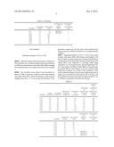
Test Example 6
Reference Numbers C32A to C39A
[0095] With the exception that the protective coating layer 13 is formed by use of a thermosetting resin having a hardness of A80, the coated polymer clad optical fiber 10 having high NA was produced in a way similar to the case of Test Example 1.
[0096] The excitation losses thereof were measured. As shown in Table 6, under the condition of the coated polymer clad optical fiber 10 in which the thickness of the polymer cladding layer 12 is 1.5 or more times the thickness of the protective coating layer 13, the value of the excitation loss does not increase, and the excitation loss was approximately 3 dB/km.
[0097] Regarding Numbers C37A to C39A of the coated polymer clad optical fibers 10 (having overall length of 20 km), in order to evaluate resistance to ironing of the produced coated polymer clad optical fibers 10, the coated polymer clad optical fibers were subjected to rewinding while being extended so as to be longer than the original length thereof by 2% of the length. Thereafter, visible light was launched into the optical fiber 11, and whether or not the excitation light leaked was evaluated. As a result of the evaluation, it was observed that the leakage of the excitation light (generation of bright spot) occurred at several portions due to ironing, and the excitation loss thereof increased by approximately 1.5 to 3.2 dB/km as compared with before the ironing.
TABLE-US-00006 TABLE 6 DEGREE OF THICKNESS HARDNESS OF OF PROTECTIVE THICKNESS PROTECTIVE PROTECTIVE FIBER CLADDING COATING OF COATING COATING NUMBER DIAMETER DIAMETER DIAMETER CLADDING LAYER LAYER C32A 125 160 250 17.5 45 A80 C33A 125 170 250 22.5 40 A80 C34A 125 175 250 25 37.5 A80 C35A 125 185 250 30 32.5 A80 C36A 125 190 250 32.5 30 A80 C37A 125 190 235 32.5 22.5 A80 C38A 125 200 250 37.5 25 A80 C39A 125 210 250 42.5 20 A80 GENERATION INCREMENT OF IN THICKNESS EXCITATION BRIGHT EXCITATION NUMBER RATIO LOSS SPOT LOSS C32A 0.4 125 -- -- C33A 0.6 100 -- -- C34A 0.7 70 -- -- C35A 0.9 40 -- -- C36A 1.1 13 -- -- C37A 1.4 3 PRESENCE 2.3 C38A 1.5 2.9 PRESENCE 3.2 C39A 2.1 3.1 PRESENCE 1.5
[0098] FIG. 4 is a chart collectively showing the relationships between thickness ratios according to the first embodiment and excitation losses (dB/km).
[0099] "125 μm (D75)" represents Test Example 1, "125 μm (D50)" represents Test Example 4, "125 μm (D20)" represents Test Example 5, "125 μm (A80)" represents Test Example 6, "80 μm (D75)" represents Test Example 2, and "400 μm (D75)" represents Test Example 3.
Test Example of Second Embodiment
[0100] In the above-described second embodiment, a resin having a hardness of D20 or more is used to form the protective coating layer 24, and the total thickness of the polymer cladding layer 22 and the buffer layer 23 is 3.0 or more times the thickness of the protective coating layer 24. As a result, it is possible to manufacture the coated polymer clad optical fiber 20 that satisfies both resistance to ironing and a low degree of excitation loss.
[0101] Of the manufactured coated polymer clad optical fibers 20 shown in Tables 7 to 16, the coated polymer clad optical fibers which are represented by the number having the initial character denoted by "C" are Comparative Examples. That is, the coated polymer clad optical fibers shown by the numbers C1B to C50B represent Comparative Examples.
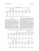
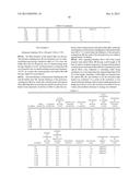
[0102] In Tables 7 to 16, the units of "FIBER DIAMETER", "CLADDING DIAMETER", "OUTER DIAMETER OF BUFFER LAYER", "PROTECTIVE COATING DIAMETER", "THICKNESS OF CLADDING", "THICKNESS OF BUFFER LAYER", "TOTAL THICKNESS OF CLADDING AND BUFFER LAYER", and "THICKNESS OF PROTECTIVE COATING LAYER" are "μm", the units of "EXCITATION LOSS" and "INCREMENT IN EXCITATION LOSS" are "dB/km", and the units thereof which are commonly used are omitted.
[0103] The "FIBER DIAMETER" represents a glass diameter of the optical fiber 21. "CLADDING DIAMETER" and "THICKNESS OF CLADDING" represent the outer diameter and the thickness of the polymer cladding layer 22, respectively. "OUTER DIAMETER OF BUFFER LAYER" and "THICKNESS OF BUFFER LAYER" represent the outer diameter of and the thickness of the buffer layer 23, respectively. "PROTECTIVE COATING DIAMETER" and "THICKNESS OF PROTECTIVE COATING LAYER" represent the outer diameter of and the thickness of the protective coating layer 24, respectively. "TOTAL THICKNESS OF CLADDING AND BUFFER LAYER" represents the total of "THICKNESS OF CLADDING" and "THICKNESS OF BUFFER LAYER".
[0104] "THICKNESS RATIO X" is the ratio of "THICKNESS OF CLADDING" to "THICKNESS OF BUFFER LAYER".
[0105] "THICKNESS RATIO Y" is the ratio of "TOTAL THICKNESS OF CLADDING AND BUFFER LAYER" to "THICKNESS OF PROTECTIVE COATING LAYER".
Test Example 7
Reference Numbers 1B to 3B and C1B to C5B
[0106] The fiber diameter of the optical fiber was 125 μm. The polymer cladding layer 22 was formed by use of a thermosetting resin having a refractive index of 1.35 or less, the buffer layer 23 was formed by use of a thermosetting resin having a hardness of A20, and the protective coating layer 24 was formed by use of a thermosetting resin having a hardness of D75. As a result, the coated polymer clad optical fiber 20 having a high NA was produced.
[0107] The total thickness of the polymer cladding layer 22 and the buffer layer 23, and the thickness of the protective coating layer 24 were varied, the coated polymer clad optical fibers 20 using them were produced, and the excitation losses thereof were measured. As shown in Table 7, under the condition of the coated polymer clad optical fiber 20 in which the total thickness of the polymer cladding layer 22 and the buffer layer 23 is 1.5 or more times the thickness of the protective coating layer 24, the value of the excitation loss was stable at approximately 3 dB/km.
[0108] Next, regarding Numbers 1B to 3B of the coated polymer clad optical fibers 20 (having overall length of 20 km), in order to evaluate resistance to ironing of the produced coated polymer clad optical fibers 20, the coated polymer clad optical fibers were subjected to rewinding while being extended so as to be longer than the original length thereof by 2% of the length. Thereafter, visible light was launched into the optical fiber 21, and whether or not the excitation light leaked was evaluated. As a result of the evaluation, it was observed that the leakage of the excitation light (generation of bright spot) did not occur, the excitation loss thereof was not varied, and excellent resistance to ironing was obtained.
TABLE-US-00007 TABLE 7 TOTAL THICKNESS OUTER OF THICKNESS DIAMETER THICKNESS CLADDING OF OF PROTECTIVE THICKNESS OF AND PROTECTIVE FIBER CLADDING BUFFER COATING OF BUFFER BUFFER COATING NUMBER DIAMETER DIAMETER LAYER DIAMETER CLADDING LAYER LAYER LAYER 1B 125 170 230 300 22.5 30 52.5 35 2B 125 170 200 250 22.5 15 37.5 25 3B 125 190 240 300 32.5 25 57.5 30 C1B 125 145 160 250 10 7.5 17.5 45 C2B 125 145 185 300 10 20 30 57.5 C3B 125 160 195 300 17.5 17.5 35 52.5 C4B 125 170 210 300 22.5 20 42.5 45 C5B 125 170 210 290 22.5 20 42.5 40 DEGREE DEGREE OF OF HARDNESS HARDNESS OF GENERATION INCREMENT OF PROTECTIVE OF IN BUFFER COATING THICKNESS THICKNESS EXCITATION BRIGHT EXCITATION NUMBER LAYER LAYER RATIO X RATIO Y LOSS SPOT LOSS 1B A20 D75 0.8 1.5 3 ABSENCE 0 2B A20 D75 1.5 1.5 2.9 ABSENCE 0 3B A20 D75 1.3 1.9 3 ABSENCE 0 C1B A20 D75 1.3 0.4 125 -- -- C2B A20 D75 0.5 0.5 100 -- -- C3B A20 D75 1.0 0.7 70 -- -- C4B A20 D75 1.1 0.9 30 -- -- C5B A20 D75 1.1 1.1 13 -- --
Test Example 8
Reference Numbers 4B to 8B and C6B to C11B
[0109] The fiber diameter of the optical fiber was 125 μm. The polymer cladding layer 22 was formed by use of a thermosetting resin having a refractive index of 1.35 or less, the buffer layer 23 was formed by use of a thermosetting resin having a hardness of A25, and the protective coating layer 24 was formed by use of a thermosetting resin having a hardness of D75. As a result, the coated polymer clad optical fiber 20 having a high NA was produced.
[0110] The total thickness of the polymer cladding layer 22 and the buffer layer 23, and the thickness of the protective coating layer 24 were varied, the coated polymer clad optical fibers 20 using them were produced, and the excitation losses thereof were measured. As shown in Table 8, under the condition of the coated polymer clad optical fiber 20 in which the total thickness of the polymer cladding layer 22 and the buffer layer 23 is 1.5 or more times the thickness of the protective coating layer 24, the value of the excitation loss was stable at approximately 3 dB/km.
[0111] Next, regarding Numbers 4B to 8B of the coated polymer clad optical fibers 20 (having overall length of 20 km), in order to evaluate resistance to ironing of the produced coated polymer clad optical fibers 20, the coated polymer clad optical fibers were subjected to rewinding while being extended so as to be longer than the original length thereof by 2% of the length. Thereafter, visible light was launched into the optical fiber 21, and whether or not the excitation light leaked was evaluated. As a result of the evaluation, it was observed that the leakage of the excitation light (generation of bright spot) did not occur, the excitation loss thereof was not varied, and excellent resistance to ironing was obtained.
TABLE-US-00008 TABLE 8 TOTAL THICKNESS OUTER OF THICKNESS DIAMETER THICKNESS CLADDING OF OF PROTECTIVE THICKNESS OF AND PROTECTIVE FIBER CLADDING BUFFER COATING OF BUFFER BUFFER COATING NUMBER DIAMETER DIAMETER LAYER DIAMETER CLADDING LAYER LAYER LAYER 4B 125 170 230 300 22.5 30 52.5 35 5B 125 170 200 250 22.5 15 37.5 25 6B 125 190 250 305 32.5 30 62.5 27.5 7B 125 170 270 305 22.5 50 72.5 17.5 8B 125 150 200 230 12.5 25 37.5 15 C6B 125 160 185 300 17.5 12.5 30 57.5 C7B 125 160 190 300 17.5 15 32.5 55 C8B 125 160 195 300 17.5 17.5 35 52.5 C9B 125 170 210 300 22.5 20 42.5 45 C10B 125 170 215 300 22.5 22.5 45 42.5 C11B 125 190 225 300 32.5 17.5 50 37.5 DEGREE DEGREE OF OF HARDNESS HARDNESS OF GENERATION INCREMENT OF PROTECTIVE OF IN BUFFER COATING THICKNESS THICKNESS EXCITATION BRIGHT EXCITATION NUMBER LAYER LAYER RATIO X RATIO Y LOSS SPOT LOSS 4B A25 D75 0.8 1.5 2.9 ABSENCE 0 5B A25 D75 1.5 1.5 2.9 ABSENCE 0 6B A25 D75 1.1 2.3 3.1 ABSENCE 0 7B A25 D75 0.5 4.1 3 ABSENCE 0 8B A25 D75 0.5 2.5 3 ABSENCE 0 C6B A25 D75 1.4 0.5 100 -- -- C7B A25 D75 1.2 0.6 90 -- -- C8B A25 D75 1.0 0.7 65 -- -- C9B A25 D75 1.1 0.9 38 -- -- C10B A25 D75 1.0 1.1 13 -- -- C11B A25 D75 1.9 1.3 4.5 -- --
Test Example 9
Reference Numbers 9B to 12B and C12B to C17B
[0112] The fiber diameter of the optical fiber was 80 μm. The polymer cladding layer 22 was formed by use of a thermosetting resin having a refractive index of 1.35 or less, the buffer layer 23 was formed by use of a thermosetting resin having a hardness of A25, and the protective coating layer 24 was formed by use of a thermosetting resin having a hardness of D75. As a result, the coated polymer clad optical fiber 20 having a high NA was produced.
[0113] The total thickness of the polymer cladding layer 22 and the buffer layer 23, and the thickness of the protective coating layer 24 were varied, the coated polymer clad optical fibers 20 using them were produced, and the excitation losses thereof were measured. As shown in Table 9, under the condition of the coated polymer clad optical fiber 20 in which the total thickness of the polymer cladding layer 22 and the buffer layer 23 is 1.5 or more times the thickness of the protective coating layer 24, the value of the excitation loss was stable at approximately 10 dB/km.
[0114] Next, regarding Numbers 9B to 12B of the coated polymer clad optical fibers 20 (having overall length of 20 km), in order to evaluate resistance to ironing of the produced coated polymer clad optical fibers 20, the coated polymer clad optical fibers were subjected to rewinding while being extended so as to be longer than the original length thereof by 2% of the length. Thereafter, visible light was launched into the optical fiber 21, and whether or not the excitation light leaked was evaluated. As a result of the evaluation, it was observed that the leakage of the excitation light (generation of bright spot) did not occur, the excitation loss thereof was not varied, and excellent resistance to ironing was obtained.
TABLE-US-00009 TABLE 9 TOTAL THICKNESS OUTER OF THICKNESS DIAMETER THICKNESS CLADDING OF OF PROTECTIVE THICKNESS OF AND PROTECTIVE FIBER CLADDING BUFFER COATING OF BUFFER BUFFER COATING NUMBER DIAMETER DIAMETER LAYER DIAMETER CLADDING LAYER LAYER LAYER 9B 80 110 215 300 15 52.5 67.5 42.5 10B 80 120 230 300 20 55 75 35 11B 80 150 270 300 35 60 95 15 12B 80 150 280 300 35 65 100 10 C12B 80 110 135 250 15 12.5 27.5 57.5 C13B 80 110 145 250 15 17.5 32.5 52.5 C14B 80 110 150 250 15 20 35 50 C15B 80 110 165 250 15 27.5 42.5 42.5 C16B 80 120 170 250 20 25 45 40 C17B 80 120 175 250 20 27.5 47.5 37.5 DEGREE DEGREE OF OF HARDNESS HARDNESS OF GENERATION INCREMENT OF PROTECTIVE OF IN BUFFER COATING THICKNESS THICKNESS EXCITATION BRIGHT EXCITATION NUMBER LAYER LAYER RATIO X RATIO Y LOSS SPOT LOSS 9B A25 D75 0.3 1.6 10 ABSENCE 0 10B A25 D75 0.4 2.1 9.8 ABSENCE 0 11B A25 D75 0.6 6.3 10.2 ABSENCE 0 12B A25 D75 0.5 10.0 10.1 ABSENCE 0 C12B A25 D75 1.2 0.5 131 -- -- C13B A25 D75 0.9 0.6 103 -- -- C14B A25 D75 0.8 0.7 71 -- -- C15B A25 D75 0.5 1.0 37 -- -- C16B A25 D75 0.8 1.1 23 -- -- C17B A25 D75 0.7 1.3 16 -- --
Test Example 10
Reference Numbers 13B to 16B and C18B to C22B
[0115] The fiber diameter of the optical fiber was 400 μm. The polymer cladding layer 22 was formed by use of a thermosetting resin having a refractive index of 1.35 or less, the buffer layer 23 was formed by use of a thermosetting resin having a hardness of A25, and the protective coating layer 24 was formed by use of a thermosetting resin having a hardness of D75. As a result, the coated polymer clad optical fiber 20 having a high NA was produced.
[0116] The total thickness of the polymer cladding layer 22 and the buffer layer 23, and the thickness of the protective coating layer 24 were varied, the coated polymer clad optical fibers 20 using them were produced, and the excitation losses thereof were measured. As shown in Table 10, under the condition of the coated polymer clad optical fiber 20 in which the total thickness of the polymer cladding layer 22 and the buffer layer 23 is 1.5 or more times the thickness of the protective coating layer 24, the value of the excitation loss was stable at approximately 3 dB/km.
[0117] Next, regarding Numbers 13B to 16B of the coated polymer clad optical fibers 20 (having overall length of 20 km), in order to evaluate resistance to ironing of the produced coated polymer clad optical fibers 20, the coated polymer clad optical fibers were subjected to rewinding while being extended so as to be longer than the original length thereof by 2% of the length. Thereafter, visible light was launched into the optical fiber 21, and whether or not the excitation light leaked was evaluated. As a result of the evaluation, it was observed that the leakage of the excitation light (generation of bright spot) did not occur, the excitation loss thereof was not varied, and excellent resistance to ironing was obtained.
TABLE-US-00010 TABLE 10 TOTAL THICKNESS OUTER OF THICKNESS DIAMETER THICKNESS CLADDING OF OF PROTECTIVE THICKNESS OF AND PROTECTIVE FIBER CLADDING BUFFER COATING OF BUFFER BUFFER COATING NUMBER DIAMETER DIAMETER LAYER DIAMETER CLADDING LAYER LAYER LAYER 13B 400 430 480 530 15 25 40 25 14B 400 440 490 530 20 25 45 20 15B 400 440 500 540 20 30 50 20 16B 400 500 520 540 50 10 60 10 C18B 400 430 450 550 15 10 25 50 C19B 400 440 455 550 20 7.5 27.5 47.5 C20B 400 440 460 550 20 10 30 45 C21B 400 440 480 550 20 20 40 35 C22B 400 440 480 540 20 20 40 30 DEGREE DEGREE OF OF HARDNESS HARDNESS OF GENERATION INCREMENT OF PROTECTIVE OF IN BUFFER COATING THICKNESS THICKNESS EXCITATION BRIGHT EXCITATION NUMBER LAYER LAYER RATIO X RATIO Y LOSS SPOT LOSS 13B A25 D75 0.6 1.6 3 ABSENCE 0 14B A25 D75 0.8 2.3 3.2 ABSENCE 0 15B A25 D75 0.7 2.5 2.8 ABSENCE 0 16B A25 D75 5.0 6.0 3.1 ABSENCE 0 C18B A25 D75 1.5 0.5 104 -- -- C19B A25 D75 2.7 0.6 92 -- -- C20B A25 D75 2.0 0.7 75 -- -- C21B A25 D75 1.0 1.1 16 -- -- C22B A25 D75 1.0 1.3 5.1 -- --
Test Example 11
Reference Numbers 17B to 20B and C23B to C26B
[0118] The fiber diameter of the optical fiber was 125 μm. The polymer cladding layer 22 was formed by use of a thermosetting resin having a refractive index of 1.35 or less, the buffer layer 23 was formed by use of a thermosetting resin having a hardness of A50, and the protective coating layer 24 was formed by use of a thermosetting resin having a hardness of D75. As a result, the coated polymer clad optical fiber 20 having a high NA was produced.
[0119] The total thickness of the polymer cladding layer 22 and the buffer layer 23, and the thickness of the protective coating layer 24 were varied, the coated polymer clad optical fibers 20 using them were produced, and the excitation losses thereof were measured. As shown in Table 11, under the condition of the coated polymer clad optical fiber 20 in which the total thickness of the polymer cladding layer 22 and the buffer layer 23 is 1.5 or more times the thickness of the protective coating layer 24, the value of the excitation loss was stable at approximately 3 dB/km.
[0120] Next, regarding Numbers 17B to 20B of the coated polymer clad optical fibers 20 (having overall length of 20 km), in order to evaluate resistance to ironing of the produced coated polymer clad optical fibers 20, the coated polymer clad optical fibers were subjected to rewinding while being extended so as to be longer than the original length thereof by 2% of the length. Thereafter, visible light was launched into the optical fiber 21, and whether or not the excitation light leaked was evaluated. As a result of the evaluation, it was observed that the leakage of the excitation light (generation of bright spot) did not occur, the excitation loss thereof was not varied, and excellent resistance to ironing was obtained.
TABLE-US-00011 TABLE 11 TOTAL THICKNESS OUTER OF THICKNESS DIAMETER THICKNESS CLADDING OF OF PROTECTIVE THICKNESS OF AND PROTECTIVE FIBER CLADDING BUFFER COATING OF BUFFER BUFFER COATING NUMBER DIAMETER DIAMETER LAYER DIAMETER CLADDING LAYER LAYER LAYER 17B 125 170 200 250 22.5 15 37.5 25 18B 125 190 235 300 32.5 22.5 55 32.5 19B 125 190 240 300 32.5 25 57.5 30 20B 125 190 250 300 32.5 30 62.5 25 C23B 125 150 170 250 12.5 10 22.5 40 C24B 125 150 175 250 12.5 12.5 25 37.5 C25B 125 160 190 250 17.5 15 32.5 30 C26B 125 170 195 250 22.5 12.5 35 27.5 DEGREE DEGREE OF OF HARDNESS HARDNESS OF GENERATION INCREMENT OF PROTECTIVE OF IN BUFFER COATING THICKNESS THICKNESS EXCITATION BRIGHT EXCITATION NUMBER LAYER LAYER RATIO X RATIO Y LOSS SPOT LOSS 17B A50 D75 1.5 1.5 2.8 ABSENCE 0 18B A50 D75 1.4 1.7 2.9 ABSENCE 0 19B A50 D75 1.3 1.9 2.8 ABSENCE 0 20B A50 D75 1.1 2.5 2.9 ABSENCE 0 C23B A50 D75 1.3 0.6 105 -- -- C24B A50 D75 1.0 0.7 75 -- -- C25B A50 D75 1.2 1.1 33 -- -- C26B A50 D75 1.8 1.3 8 -- --
Test Example 12
Reference Numbers 21B to 22B and C27B to C32B
[0121] The fiber diameter of the optical fiber was 125 μm. The polymer cladding layer 22 was formed by use of a thermosetting resin having a refractive index of 1.35 or less, the buffer layer 23 was formed by use of a thermosetting resin having a hardness of A75, and the protective coating layer 24 was formed by use of a thermosetting resin having a hardness of D75. As a result, the coated polymer clad optical fiber 20 having a high NA was produced.
[0122] The total thickness of the polymer cladding layer 22 and the buffer layer 23, and the thickness of the protective coating layer 24 were varied, the coated polymer clad optical fibers 20 using them were produced, and the excitation losses thereof were measured. As shown in Table 12, under the condition of the coated polymer clad optical fiber 20 in which the total thickness of the polymer cladding layer 22 and the buffer layer 23 is 1.5 or more times the thickness of the protective coating layer 24, the value of the excitation loss was stable at approximately 3 dB/km.
[0123] Next, regarding Numbers 21B to 22B of the coated polymer clad optical fibers 20 (having overall length of 20 km), in order to evaluate resistance to ironing of the produced coated polymer clad optical fibers 20, the coated polymer clad optical fibers were subjected to rewinding while being extended so as to be longer than the original length thereof by 2% of the length. Thereafter, visible light was launched into the optical fiber 21, and whether or not the excitation light leaked was evaluated. As a result of the evaluation, it was observed that the leakage of the excitation light (generation of bright spot) did not occur, the excitation loss thereof was not varied, and excellent resistance to ironing was obtained.
TABLE-US-00012 TABLE 12 TOTAL THICKNESS OUTER OF THICKNESS DIAMETER THICKNESS CLADDING OF OF PROTECTIVE THICKNESS OF AND PROTECTIVE FIBER CLADDING BUFFER COATING OF BUFFER BUFFER COATING NUMBER DIAMETER DIAMETER LAYER DIAMETER CLADDING LAYER LAYER LAYER 21B 125 190 200 250 32.5 5 37.5 25 22B 125 170 250 300 22.5 40 62.5 25 C27B 125 160 185 300 17.5 12.5 30 57.5 C28B 125 160 190 300 17.5 15 32.5 55 C29B 125 160 195 300 17.5 17.5 35 52.5 C30B 125 170 215 300 22.5 22.5 45 42.5 C31B 125 170 225 300 22.5 27.5 50 37.5 C32B 125 160 190 300 17.5 15 32.5 55 DEGREE DEGREE OF OF HARDNESS HARDNESS OF GENERATION INCREMENT OF PROTECTIVE OF IN BUFFER COATING THICKNESS THICKNESS EXCITATION BRIGHT EXCITATION NUMBER LAYER LAYER RATIO X RATIO Y LOSS SPOT LOSS 21B A75 D75 6.5 1.5 2.9 ABSENCE 0 22B A75 D75 0.6 2.5 2.9 ABSENCE 0 C27B A75 D75 1.4 0.5 105 -- -- C28B A75 D75 1.2 0.6 93 -- -- C29B A75 D75 1.0 0.7 66 -- -- C30B A75 D75 1.0 1.1 14 -- -- C31B A75 D75 0.8 1.3 5.1 -- -- C32B A75 D75 1.2 0.6 98 -- --
Test Example 13
Reference Numbers 23B to 24B and C33B to C37B
[0124] The fiber diameter of the optical fiber was 125 μm. The polymer cladding layer 22 was formed by use of a thermosetting resin having a refractive index of 1.35 or less, the buffer layer 23 was formed by use of a thermosetting resin having a hardness of A80, and the protective coating layer 24 was formed by use of a thermosetting resin having a hardness of D75. As a result, the coated polymer clad optical fiber 20 having a high NA was produced.
[0125] The total thickness of the polymer cladding layer 22 and the buffer layer 23, and the thickness of the protective coating layer 24 were varied, the coated polymer clad optical fibers 20 using them were produced, and the excitation losses thereof were measured. As shown in Table 13, under the condition of the coated polymer clad optical fiber 20 in which the total thickness of the polymer cladding layer 22 and the buffer layer 23 is 1.5 or more times the thickness of the protective coating layer 24, the value of the excitation loss was stable at approximately 3 dB/km.
[0126] Next, regarding Numbers 23B to 24B of the coated polymer clad optical fibers 20 (having overall length of 20 km), in order to evaluate resistance to ironing of the produced coated polymer clad optical fibers 20, the coated polymer clad optical fibers were subjected to rewinding while being extended so as to be longer than the original length thereof by 2% of the length. Thereafter, visible light was launched into the optical fiber 21, and whether or not the excitation light leaked was evaluated. As a result of the evaluation, it was observed that the leakage of the excitation light (generation of bright spot) did not occur, the excitation loss thereof was not varied, and excellent resistance to ironing was obtained.
TABLE-US-00013 TABLE 13 TOTAL THICKNESS OUTER OF THICKNESS DIAMETER THICKNESS CLADDING OF OF PROTECTIVE THICKNESS OF AND PROTECTIVE FIBER CLADDING BUFFER COATING OF BUFFER BUFFER COATING NUMBER DIAMETER DIAMETER LAYER DIAMETER CLADDING LAYER LAYER LAYER 23B 125 170 200 250 22.5 15 37.5 25 24B 125 190 240 300 32.5 25 57.5 30 C33B 125 160 200 300 17.5 20 37.5 50 C34B 125 160 210 300 17.5 25 42.5 45 C35B 125 160 220 300 17.5 30 47.5 40 C36B 125 160 195 250 17.5 17.5 35 27.5 C37B 125 170 195 245 22.5 12.5 35 25 DEGREE DEGREE OF OF HARDNESS HARDNESS OF GENERATION INCREMENT OF PROTECTIVE OF IN BUFFER COATING THICKNESS THICKNESS EXCITATION BRIGHT EXCITATION NUMBER LAYER LAYER RATIO X RATIO Y LOSS SPOT LOSS 23B A80 D75 1.5 1.5 2.9 ABSENCE 0 24B A80 D75 1.3 1.9 2.9 ABSENCE 0 C33B A80 D75 0.9 0.8 62 -- -- C34B A80 D75 0.7 0.9 43 -- -- C35B A80 D75 0.6 1.2 13 -- -- C36B A80 D75 1.0 1.3 10 -- -- C37B A80 D75 1.8 1.4 4.5 -- --
Test Example 14
Reference Numbers C38B to C44B
[0127] The fiber diameter of the optical fiber was 125 μm. The polymer cladding layer 22 was formed by use of a thermosetting resin having a refractive index of 1.35 or less, the buffer layer 23 was formed by use of a thermosetting resin having a hardness of D20, and the protective coating layer 24 was formed by use of a thermosetting resin having a hardness of D75. As a result, the coated polymer clad optical fiber 20 having a high NA was produced.
[0128] The total thickness of the polymer cladding layer 22 and the buffer layer 23, and the thickness of the protective coating layer 24 were varied, the coated polymer clad optical fibers 20 using them were produced, and the excitation losses thereof were measured. As shown in Table 14, even under the condition of the coated polymer clad optical fiber 20 in which the total thickness of the polymer cladding layer 22 and the buffer layer 23 is 1.5 or more times the thickness of the protective coating layer 24, the value of the excitation loss was greater than or equal to 10 dB/km.
[0129] In the case (C44B) of particularly reducing the thickness of the buffer layer 23, the value of the excitation loss was stable at approximately 3 dB/km.
TABLE-US-00014 TABLE 14 TOTAL THICKNESS OUTER OF THICKNESS DIAMETER THICKNESS CLADDING OF OF PROTECTIVE THICKNESS OF AND PROTECTIVE FIBER CLADDING BUFFER COATING OF BUFFER BUFFER COATING NUMBER DIAMETER DIAMETER LAYER DIAMETER CLADDING LAYER LAYER LAYER C38B 125 175 205 250 25 15 40 22.5 C39B 125 190 230 250 32.5 20 52.5 10 C40B 125 200 235 250 37.5 17.5 55 7.5 C41B 125 215 250 270 45 17.5 62.5 10 C42B 125 220 250 270 47.5 15 62.5 10 C43B 125 230 250 270 52.5 10 62.5 10 C44B 125 235 250 270 55 7.5 62.5 10 DEGREE DEGREE OF OF HARDNESS HARDNESS OF GENERATION INCREMENT OF PROTECTIVE OF IN BUFFER COATING THICKNESS THICKNESS EXCITATION BRIGHT EXCITATION NUMBER LAYER LAYER RATIO X RATIO Y LOSS SPOT LOSS C38B D20 D75 1.7 1.3 140 -- -- C39B D20 D75 1.6 5.3 106 -- -- C40B D20 D75 2.1 7.3 55 -- -- C41B D20 D75 2.6 6.3 39 -- -- C42B D20 D75 3.2 6.3 30 -- -- C43B D20 D75 5.3 6.3 15 -- -- C44B D20 D75 7.3 6.3 3 -- --
Test Example 15
Reference Numbers C45B to C50B
[0130] The fiber diameter of the optical fiber was 125 The polymer cladding layer 22 was formed by use of a thermosetting resin having a refractive index of 1.35 or less, the buffer layer 23 was formed by use of a thermosetting resin having a penetration of 45, and the protective coating layer 24 was formed by use of a thermosetting resin having a hardness of D75. As a result, the coated polymer clad optical fiber 20 having a high NA was produced.
[0131] The total thickness of the polymer cladding layer 22 and the buffer layer 23, and the thickness of the protective coating layer 24 were varied, the coated polymer clad optical fibers 20 using them were produced, and the excitation losses thereof were measured. As shown in Table 15, under the condition of the coated polymer clad optical fiber 20 in which the total thickness of the polymer cladding layer 22 and the buffer layer 23 is 1.5 or more times the thickness of the protective coating layer 24, the value of the excitation loss was stable at approximately 3 dB/km.
[0132] Regarding Numbers C48B to C50B of the coated polymer clad optical fibers 20 (having overall length of 20 km), in order to evaluate resistance to ironing of the produced coated polymer clad optical fibers 20, the coated polymer clad optical fibers were subjected to rewinding while being extended so as to be longer than the original length thereof by 2% of the length. In this case, it was observed that part of the coated polymer clad optical fiber 20 is deformed in appearance. Furthermore, visible light was launched into the optical fiber 21, and whether or not the excitation light leaked was evaluated. As a result of the evaluation, the leakage of the excitation light (generation of bright spot) occurred at the deformed part of the coated polymer clad optical fiber.
TABLE-US-00015 TABLE 15 TOTAL THICKNESS OUTER OF THICKNESS DIAMETER THICKNESS CLADDING OF OF PROTECTIVE THICKNESS OF AND PROTECTIVE FIBER CLADDING BUFFER COATING OF BUFFER BUFFER COATING NUMBER DIAMETER DIAMETER LAYER DIAMETER CLADDING LAYER LAYER LAYER C45B 125 150 175 250 12.5 12.5 25 37.5 C46B 125 150 190 250 12.5 20 32.5 30 C47B 125 150 195 250 12.5 22.5 35 27.5 C48B 125 150 200 250 12.5 25 37.5 25 C49B 125 150 220 250 12.5 35 47.5 15 C50B 125 190 280 300 32.5 45 77.5 10 DEGREE DEGREE OF OF HARDNESS HARDNESS OF GENERATION INCREMENT OF PROTECTIVE OF IN BUFFER COATING THICKNESS THICKNESS EXCITATION BRIGHT EXCITATION NUMBER LAYER LAYER RATIO X RATIO Y LOSS SPOT LOSS C45B PENETRATION D75 1.0 0.7 71 -- -- OF 45 C46B PENETRATION D75 0.6 1.1 37 -- -- OF 45 C47B PENETRATION D75 0.6 1.3 16 -- -- OF 45 C48B PENETRATION D75 0.5 1.5 3.1 PRESENCE 5 OF 45 C49B PENETRATION D75 0.4 3.2 3 PRESENCE 4 OF 45 C50B PENETRATION D75 0.7 7.8 3.1 PRESENCE 6 OF 45
Test Example 16
Reference Numbers 25B to 29B
[0133] The fiber diameter of the optical fiber was 125 μm. The polymer cladding layer 22 was formed by use of a thermosetting resin having a refractive index of 1.35 or less, the buffer layer 23 was formed by use of a thermosetting resin having a hardness of A25, and the protective coating layer 24 was formed by use of a thermosetting resin having a hardness of D20. As a result, the coated polymer clad optical fiber 20 having a high NA was produced.
[0134] The ratio of total thickness of the polymer cladding layer 22 and the buffer layer 23 to the thickness of the protective coating layer 24 were fixed at 1.5, thicknesses of the polymer cladding layer 22 and the buffer layer 23 were varied, the coated polymer clad optical fibers 20 using them were produced, and the excitation losses thereof were measured. As shown in Table 16, the value of the excitation loss was approximately 3 dB/km in the range of 2.5 to 32.5 μm of the thickness of the polymer cladding layer 22.
[0135] Next, regarding Numbers 25B to 29B of the coated polymer clad optical fibers 20 (having overall length of 20 km), in order to evaluate resistance to ironing of the produced coated polymer clad optical fibers 20, the coated polymer clad optical fibers were subjected to rewinding while being extended so as to be longer than the original length thereof by 2% of the length. Thereafter, visible light was launched into the optical fiber 21, and whether or not the excitation light leaked was evaluated. As a result of the evaluation, it was observed that the leakage of the excitation light (generation of bright spot) did not occur, the excitation loss thereof was not varied, and excellent resistance to ironing was obtained.
TABLE-US-00016 TABLE 16 TOTAL THICKNESS OUTER OF THICKNESS DIAMETER THICKNESS CLADDING OF OF PROTECTIVE THICKNESS OF AND PROTECTIVE FIBER CLADDING BUFFER COATING OF BUFFER BUFFER COATING NUMBER DIAMETER DIAMETER LAYER DIAMETER CLADDING LAYER LAYER LAYER 25B 125 180 200 250 27.5 10 37.5 25 26B 125 130 200 250 2.5 35 37.5 25 27B 125 140 200 250 7.5 30 37.5 25 28B 125 160 200 250 17.5 20 37.5 25 29B 125 190 200 250 32.5 5 37.5 25 DEGREE DEGREE OF OF HARDNESS HARDNESS OF GENERATION INCREMENT OF PROTECTIVE OF IN BUFFER COATING THICKNESS THICKNESS EXCITATION BRIGHT EXCITATION NUMBER LAYER LAYER RATIO X RATIO Y LOSS SPOT LOSS 25B A25 D20 2.8 1.5 3.1 ABSENCE 0 26B A25 D20 0.1 1.5 3 ABSENCE 0 27B A25 D20 0.3 1.5 2.9 ABSENCE 0 28B A25 D20 0.9 1.5 3 ABSENCE 0 29B A25 D20 6.5 1.5 3.2 ABSENCE 0
[0136] FIG. 5 is a chart collectively showing the relationships between thickness ratios (thickness ratio Y in Tables 7 to 16) according to the second embodiment and excitation losses (dB/km).
[0137] "125 μm (A20)" represents Test Example 7, "125 μm (A25)" represents Test Example 8, "80 μm (A25)" represents Test Example 9, "400 μm (A25)" represents Test Example 10, "125 μm (A50)" represents Test Example 11, "125 μm (A75)" represents Test Example 12, "125 μm (A80)" represents Test Example 13, "125 μm (D20)" represents Test Example 14, "125 μm (penetration 45)" represents Test Example 15, and "125 μm (A25, thickness ratio of 1.5)" represents Test Example 16.
User Contributions:
Comment about this patent or add new information about this topic:
Images included with this patent application:
 |  |
 |  |
 |  |
 |  |
 |  |
 |  |
 |  |
 |  |
 |  |
| New patent applications in this class: | |
| Date | Title |
|---|---|
| 2022-09-08 | Shrub rose plant named 'vlr003' |
| 2022-08-25 | Cherry tree named 'v84031' |
| 2022-08-25 | Miniature rose plant named 'poulty026' |
| 2022-08-25 | Information processing system and information processing method |
| 2022-08-25 | Data reassembly method and apparatus |
| New patent applications from these inventors: | |
| Date | Title |
|---|---|
| 2013-10-03 | Method and apparatus for manufacturing optical fiber |
| 2010-05-06 | Optical fiber manufacturing method and optical fiber manufacturing apparatus |