Patent application title: Containing Box Structure
Inventors:
Mu-Chuan Hsu (Miaoli County, TW)
Assignees:
L&F PLASTICS, CO., LTD.
IPC8 Class: AB65D2500FI
USPC Class:
Class name:
Publication date: 2015-08-27
Patent application number: 20150239613
Abstract:
A containing box structure includes a containing box and a lid body. The
lid body includes top and front lids. Concave portions are concavely
disposed at the edge of a top opening of the containing box. An engaging
portion with an S-shaped cross section is disposed at the edge of the
front of the containing box. The edge of the top lid extends by a length
to form abutting portions which straddle at the upper edge of the
containing box, such that hook portions of the top lid are inserted into
the concave portions, thereby effectuating precise engagement between the
top lid and the containing box. A protruding portion extends from the
lower edge of the front lid to engage with the engaging portion of the
containing box. Therefore, the containing box is covered, and thus is in
precise positional engagement, with the top lid and the front lid.Claims:
1. A containing box structure, adapted to contain objects therein, the
containing box structure comprising: a containing box adapted to contain
objects therein and having a top opening; a lid body including a top lid
and a front lid and adapted to cover the top opening of the containing
box, wherein concave portions are concavely disposed at a predetermined
portion of an edge of the top opening of the containing box, and an
engaging portion with an S-shaped cross section is disposed at a
predetermined segment at an edge of a front of the containing box,
wherein an inward side of an edge of the top lid extends by a
predetermined length to form abutting portions which straddle at the edge
of the top opening of the containing box, such that a hook portion at a
predetermined segment of the top lid is inserted into the concave
portions disposed at the predetermined portion of the edge of the top
opening of the containing box, thereby effectuating precise engagement
between the top lid and the containing box, wherein an inward side of an
edge of the front lid extends by a predetermined length to form abutting
portions for coming into tight contact with the edge of the front of the
containing box after enclosing the edge of the front of the containing
box, and a lower edge of the front lid extends by a predetermined length
to form a protruding portion for imposing positional restriction on the
engaging portion at a corresponding position on the containing box; and
the containing box is in precise positional engagement with the lid body
when covered with the top lid and the front lid of the lid body, and a
user only needs to exert a force on the front lid in order to lift the
front lid and thus open the containing box easily.
2. The containing box structure of claim 1, wherein auxiliary ribs are formed by extending by a predetermined length the inward sides of edges of the top lid and the front lid of the lid body covering the top opening of the containing box and adapted to reinforce the lid body when the containing box is covered with the top lid and the front lid of the lid body, so as to enhance tightness and stability of positional engagement between the lid body and the containing box.
3. A containing box structure, comprising a lid body and a containing box, the lid body including a top lid and a front lid and adapted to cover a top opening of the containing box, and characterized by: a curved concave region defined at a forward edge of the top lid and having a predetermined width, a guide channel formed shallowly and concavely at a predetermined segment of each of left and right ends of the curved concave region, an engaging portion formed beneath the guide channel, and a hole formed at the forward edge of the top lid to penetrate the top lid and positioned on each of two sides of the curved concave region, wherein an engagement segment formed at an upper edge of the front lid and curving outward is inserted into the curved concave region of the top lid, such that a protruding portion formed by extending an upper portion of the engagement segment is inserted into a guide channel formed concavely at each of two ends of the curved concave region, wherein branch portions formed outwardly and protrudingly on two sides of the engagement segment are inserted into the holes at the curved concave region such that the front lid is pivotally coupled to the curved concave region of the top lid; lifting the front lid relative to the curved concave region of the top lid, and moving the protruding portions on two sides of the engagement segment downward along the guide channels, respectively, such that the branch portions on the two sides of the front lid abut against the upper edges of the holes at the curved concave region as soon as the protruding portions pass the engaging portion of the curved concave region and thus their contact ends are pushed upward, and in consequence the front lid secures a positional restriction of appropriate tightness.
4. The containing box structure of claim 3, wherein a notch is disposed on each of the two sides of the engagement segment formed at the upper edge of the front lid, and the notches correspond in position to the front edge of the top lid, so as to allow the top lid to be shut or lifted smoothly when pivotally coupled to the front lid.
Description:
TECHNICAL FIELD
[0001] The present invention relates to containing box structures, and more particularly, to a containing box structure including a containing box for containing various objects and characterized in that a lid body coupled to an upper end of the containing box is in positional engagement with a top opening of the containing box so as to not only ensure a precise closure while the objects are being contained in the containing box but also render it easy to lift a top lid of the lid body.
DESCRIPTION OF RELATED ART
[0002] Conventional containing boxes for use in containing a wide variety of objects come in various shapes. For example, a plastic-made conventional containing box in wide use not only has a predetermined shape but is also lightweight and thus can be easily transported. The conventional containing boxes each essentially comprise a containing box of a predetermined capacity and shape and a lid body corresponding in outline to a top opening of the containing box and adapted to cover the top opening to not only allow the containing box to contain objects but also allow the lid body to be lifted so as for objects to be put in the containing box and/or taken out thereof.
[0003] It is rather difficult to lift the lid body adapted for covering the containing box from above. Front and rear halves of the lid body are pivotally coupled together by a rod segment thereof. Objects can be put in or taken from the containing box. When performing the lid body lifting process with a view to taking objects out of the containing box and putting objects in the containing box, a user will have to allow the front half of the lid body to rest on the rear half of the lid body unless the user holds the front half of the lid body by hand temporarily. Furthermore, the lid body for covering the top opening of the containing box is fastened thereto solely by a press; as a result, the lid body separates from the top of the containing box readily while the containing box is being transported or when subjected to a hit inadvertently
[0004] The present invention aims to solve the aforesaid problem with shutting and lifting the lid body for use in covering the containing box with a view to securing tight and stable engagement between the containing box and the lid body when the lid body is shut and ensuring that the lid body can be easily lifted.
SUMMARY OF THE INVENTION
[0005] The present invention overcomes a drawback of the prior art, that is, a lid body coupled to an upper end of a conventional containing box for containing various objects is likely to get disconnected when closed and/or lifted, such that the lid body is in positional engagement with the containing box when covering a top opening of the containing box so as to not only ensure a precise closure while the objects are being contained in the containing box but also render it easy to lift a top lid of the lid body.
[0006] It is an objective of the present invention to provide a containing box structure comprising: a containing box adapted to contain objects therein and having a top opening; a lid body including a top lid and a front lid and adapted to cover the top opening of the containing box, wherein concave portions are concavely disposed at a predetermined portion of an edge of the top opening of the containing box, and an engaging portion with an S-shaped cross section is disposed at a predetermined segment at an edge of the front of the containing box, wherein an inward side of an edge of the top lid extends by a predetermined length to form abutting portions which straddle at the edge of the top opening of the containing box, such that a hook portion at a predetermined segment of the top lid is inserted into the concave portions disposed at the predetermined portion of the edge of the top opening of the containing box, thereby effectuating precise engagement between the top lid and the containing box, wherein an inward side of an edge of the front lid extends by a predetermined length to form abutting portions for coming into tight contact with the edge of the front of the containing box after enclosing the edge of the front of the containing box, and a lower edge of the front lid extends by a predetermined length to form a protruding portion for imposing positional restriction on the engaging portion at a corresponding position on the containing box; and the containing box is in precise positional engagement with the lid body when covered with the top lid and the front lid of the lid body, and a user only needs to exert a force on the front lid in order to lift the front lid and thus open the containing box easily.
[0007] Another objective of the present invention is to provide a containing box structure characterized in that: auxiliary ribs are formed by extending by a predetermined length the inward sides of edges of the top lid and the front lid of the lid body covering the top opening of the containing box and adapted to reinforce the lid body when the containing box is covered with the top lid and the front lid of the lid body, so as to enhance tightness and stability of positional engagement between the lid body and the containing box.
[0008] Yet another objective of the present invention is to provide a containing box structure comprising a lid body and a containing box, the lid body including a top lid and a front lid and adapted to cover a top opening of the containing box, and characterized by: a curved concave region defined at a forward edge of the top lid and having a predetermined width, a guide channel formed shallowly and concavely at a predetermined segment of each of left and right ends of the curved concave region, an engaging portion formed beneath the guide channel, and a hole formed at the forward edge of the top lid to penetrate the top lid and positioned on each of two sides of the curved concave region, wherein an engagement segment formed at an upper edge of the front lid and curving outward is inserted into the curved concave region of the top lid, such that a protruding portion formed by extending an upper portion of the engagement segment is inserted into a guide channel formed concavely at each of two ends of the curved concave region, wherein branch portions formed outwardly and protrudingly on two sides of the engagement segment are inserted into the holes at the curved concave region such that the front lid is pivotally coupled to the curved concave region of the top lid; lifting the front lid relative to the curved concave region of the top lid, and moving the protruding portions on two sides of the engagement segment downward along the guide channels, respectively, such that the branch portions on the two sides of the front lid abut against the upper edges of the holes at the curved concave region as soon as the protruding portions pass the engaging portion of the curved concave region and thus their contact ends are pushed upward, and in consequence the front lid secures a positional restriction of appropriate tightness.
[0009] A further objective of the present invention is to provide form a notch on each of the two sides of the engagement segment formed at the upper edge of the front lid, and the notches correspond in position to the front edge of the top lid, so as to allow the top lid to be shut or lifted smoothly when pivotally coupled to the front lid.
BRIEF DESCRIPTION OF THE SEVERAL VIEWS OF THE DRAWINGS
[0010] FIG. 1 is a schematic exploded view of a containing box and a lid body according to the present invention;
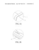
[0011] FIG. 1A is an enlarged view of portion A in FIG. 1;
[0012] FIG. 1B is an enlarged view of portion B in FIG. 1;
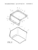
[0013] FIG. 2 is a bottom perspective view of the containing box and the lid body which are separated according to the present invention;
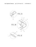
[0014] FIG. 2A is an enlarged view of portion A in FIG. 2;
[0015] FIG. 2B is an enlarged view of portion B in FIG. 2;
[0016] FIG. 2C is an enlarged view of portion C in FIG. 2;
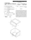
[0017] FIG. 3 is a perspective view of the containing box and the lid body which are put together according to the present invention;
[0018] FIG. 4 is a lateral schematic view of the containing box and the lid body which are put together according to the present invention;
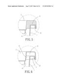
[0019] FIG. 5 is a cross-sectional view of a segment of portion A in FIG. 4;
[0020] FIG. 6 is a cross-sectional view of another segment of portion A in FIG. 4;
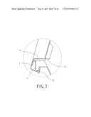
[0021] FIG. 7 is a cross-sectional view of portion B in FIG. 4;
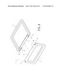
[0022] FIG. 8 is a schematic exploded view of the lid body according to the present invention;
[0023] FIG. 8A is an enlarged view of portion A in FIG. 8;
[0024] FIG. 8B is an enlarged view of portion B in FIG. 8;
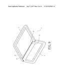
[0025] FIG. 9 is a perspective view of the lid body according to the present invention;
[0026] FIG. 10 is a lateral cross-sectional view of the lid body which covers the containing box according to the present invention;
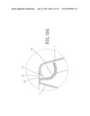
[0027] FIG. 10A is an enlarged view of portion A in FIG. 10;
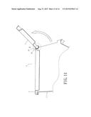
[0028] FIG. 11 is a top cross-sectional view of the lid body lifted relative to the containing box by a rotation angle of 120° approximately according to the present invention; and
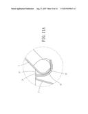
[0029] FIG. 11A is an enlarged view of portion A in FIG. 11.
DETAILED DESCRIPTION OF THE EMBODIMENT OF THE INVENTION
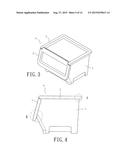
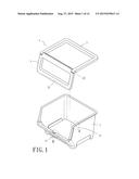
[0030] The present invention provides a containing box structure (as shown in FIG. 1, FIG. 2) for containing objects therein. The containing box structure, which opens upward and forward, comprises a containing box 1 and a lid body 4. The lid body 4 comprises a top lid 2 and a front lid 3 which are pivotally connected. As its name indicates, the front lid 3 is in front of the top lid 2.
[0031] The containing box 1 has a top opening. The top opening is covered with the lid body 4. The containing box 1 has a predetermined shape and capacity and is for use in containing objects therein. Concave portions 11 (as shown in FIG. 1A and FIG. 2) are concavely disposed at a predetermined portion of the edge of the top opening of the containing box 1. An engaging portion 12 (as shown in FIG. 1B and FIG. 7) with an S-shaped cross section is disposed at a predetermined segment at the edge of the front of the containing box 1.
[0032] The top lid 2 and the front lid 3 are pivotally connected at the junction thereof. The inward side of the edge of the top lid 2 extends by a predetermined length to form abutting portions 21 (shown in FIG. 2 and FIG. 2B). Hook portions 22 (shown in FIG. 2 and FIG. 2A) are disposed on a lower inner side at a predetermined segment of the top lid 2.
[0033] The inward side of the edge of the front lid 3 extends by a predetermined length to form abutting portions 31. The lower edge of the front lid 3 extends by a predetermined length to form a protruding portion 32 (shown in FIG. 2, FIG. 2C, FIG. 7). The inward sides of edges of the top lid 2 and the front lid 3 extend by a predetermined length to form auxiliary ribs 23, 33 (shown in FIG. 2, FIG. 2B), respectively.
[0034] Coupling together the lid body 4 and the containing box 1 (as shown in FIG. 2, FIG. 5, FIG. 6) requires performing the steps below. In the first step, the abutting portions 21, which are formed by extending an inward side of an edge of the top lid 2 of the lid body 4 by a predetermined length, straddle at the upper end of the containing box 1, and the hook portions 22 at a predetermined segment of the top lid 2 are inserted into the concave portions 11 at a predetermined portion of the edge of the top opening of the containing box 1, so as to effectuate tight positional engagement between the top lid 2 and the containing box 1. In the second step, the abutting portions 31, which are formed by extending an inward side of an edge of the front lid 3 of the lid body 4 by a predetermined length, come into tight contact with the edge of the front of the containing box 1 after enclosing the edge of the front of the containing box 1 (as shown in FIG. 7), such that the protruding portion 32, which is formed by extending the lower edge of the front lid 3 by a predetermined length, imposes positional restriction on the engaging portion 12 at a corresponding position on the containing box 1. Hence, when covered with the top lid 2 and the front lid 3 of the lid body 4 (as shown in FIG. 3, FIG. 4), the containing box 1 is in precise positional engagement with the lid body 4. To lift the front lid 3, a user only needs to exert a force on the front lid 3; hence, it is easy to open the containing box 1.
[0035] The auxiliary ribs 23, 33, which are formed by extending the inward sides of edges of the top lid 2 and the front lid 3 by a predetermined length, reinforce the lid body 4 when the containing box 1 is covered with the top lid 2 and the front lid 3 of the lid body 4, so as to enhance the tightness and stability of the positional engagement between the lid body 4 and the containing box 1.
[0036] The means of coupling together the top lid 2 and the front lid 3 of the lid body 4 for covering the top opening of the containing box 1 (as shown in FIG. 8) is described below.
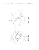
[0037] The top lid 2 of the lid body 4 is of a predetermined width depending on the rear edge of the top opening of the containing box 1 (as shown in FIG. 10). A curved concave region 24 (shown in FIG. 8) of a predetermined width is defined at the forward edge of the top lid 2. A guide channel 25 (shown in FIG. 8A) is formed shallowly and concavely at a predetermined segment of each of the left and right ends of the curved concave region 24. An engaging portion 26 is formed beneath the guide channel 25. A hole 27 is formed at the forward edge of the top lid 2 to penetrate the top lid 2 and positioned on each of the two sides of the curved concave region 24.
[0038] The front lid 3 of the lid body 4 is of a predetermined width depending on the front edge of the top opening of the containing box 1 (as shown in FIG. 10). An engagement segment 34 which curves outward is formed at the upper edge of the front lid 3. An upper portion of the engagement segment 34 extends to form a protruding portion 35 (shown in FIG. 8B). Branch portions 36 are formed outwardly and protrudingly on the two sides of the engagement segment 34, respectively. A notch 37 is disposed on each of the two sides of the engagement segment 34 formed at the upper edge of the front lid 3, and the notches 37 correspond in position to the front edge of the top lid 2, so as to allow the top lid 2 to be shut or lifted smoothly when pivotally coupled to the front lid 3.
[0039] The top lid 2 and the front lid 3 are put together by following the procedure below (shown in FIG. 8, FIG. 10): put the engagement segment 34 formed at the upper edge of the front lid 3 and curving outward in the curved concave region 24 of the top lid 2, insert the protruding portions 35 formed by extending an upper portion of the engagement segment 34 into the guide channels 25 formed concavely at the two ends of the curved concave region 24, and insert the branch portions 36 formed protrudingly on the two sides of the engagement segment 34 into the holes 27 of the curved concave region 24, such that the front lid 3 is pivotally coupled to the curved concave region 24 of the top lid 2, thereby assembling the lid body 4 (as shown in FIG. 9).
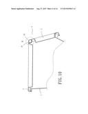
[0040] The top opening of the containing box 1 is covered with the lid body 4 thus assembled (as shown in FIG. 10 and FIG. 10A) in a manner to maintain the precise pivotal connection between the engagement segment 34 formed at the upper edge of the front lid 3 and the curved concave region 24 of the top lid 2 and allow the top lid 2 to be put down and shut, such that it is easy to close the openings of the containing box 1.
[0041] Lifting the front lid 3 with which the top opening of the containing box 1 is covered (as shown in FIG. 11) entails performing the procedure below: grip the free end of the front lid 3 and lift the front lid 3 relative to the curved concave region 24 of the top lid 2, move the protruding portions 35 on the two sides of the engagement segment 34 downward along the guide channels 25 (as shown in FIG. 11A), respectively, such that the branch portions 36 on the two sides of the front lid 3 abut against the upper edges of the holes 27 at the curved concave region 24 as soon as the protruding portions 35 pass the engaging portion 26 of the curved concave region 24 and thus their contact ends are pushed upward, and in consequence the front lid 3 secures a positional restriction of appropriate tightness. A user puts objects in the containing box 1 and takes objects out of the containing box 1. To put down the front lid 3 and shut the front lid 3, all the user needs to do is press the front lid 3 downward such that the protruding portions 35 on the two sides of the engagement segment 34 at one end of the front lid 3 get restricted by the engaging portion 26 of the guide channel 25 again (as shown in FIG. 10A) to resume the closure.
User Contributions:
Comment about this patent or add new information about this topic:
Images included with this patent application:
 |  |
 |  |
 |  |
 |  |
 |  |
 |  |
 |  |
 |
| New patent applications in this class: | |
| Date | Title |
|---|---|
| 2022-09-08 | Shrub rose plant named 'vlr003' |
| 2022-08-25 | Cherry tree named 'v84031' |
| 2022-08-25 | Miniature rose plant named 'poulty026' |
| 2022-08-25 | Information processing system and information processing method |
| 2022-08-25 | Data reassembly method and apparatus |
| New patent applications from these inventors: | |
| Date | Title |
|---|---|
| 2016-05-26 | Containing box structure |
| 2015-10-01 | Containing box structure |